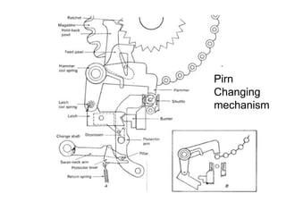
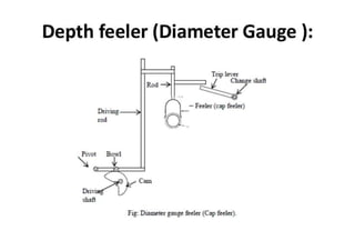
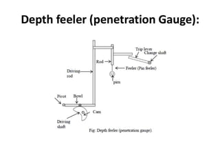
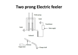
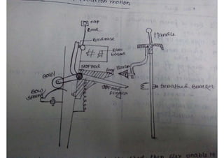
Automatic Conventional Weaving
Pirn
Changing
mechanism
Working principle of changing mechanism:
When the feeler feels that there is no yarn in the pirn, it
provides a slight rotation of changing shaft. This slight rotation of
changing shaft is activates the changing mechanism. This rotation
engaged the bunter pushed the bunter lever. Further information
that bunter is attached to the sley. This pushing force pressed the
pirn by hammer and ultimately the pirn is changed. The circular
magazine which can accommodate 24 to 30 full pirns is mounted
on the right hand of the loom. So that its bottom center is above
the shuttle when the sley is at the beat up position and the shuttle
is in its box.
Working principle of changing mechanism:
A very high percentage of single-shuttle automatic looms are equipped with the feeler unit at the
left-hand starting-handle side of the loom, so that the weft-fork hammer movement can be utilized
to assist the bobbin change that takes place one pick later at the right-hand side of the loom. The
partial rotation of the change shaft that results from the tripper heel’s pushing on the trip lever
causes the swan neck and thus the shuttle-protector lever to swing in an anti-clockwise direction
from their normal position, and this lifts the pillar and protector arm. The depressor thus releases
its hold on the latch, which then rises by virtue of its coil-spring-Ioading into a horizontal position.
As the s1ey approaches front center, the shuttle having arrived in the right-hand box, the bunter
pushes the latch, which now forms a rigid connection with the hammer. As the hammer moves in
a downward direction, it forces the bottom bobbin out of its spring-held position in the magazine
onto the top of the bobbin in the shuttle. The hammer pressure continues until the almost-empty
pirn is forced out of the shuttle (Fig. 9.6A) and through holes in the bottom of the shuttle and the
box base, and the new full pirn is positioned in the shuttle. The weft-fork cam, which has been
designed to give a full throw for a period of just over 180 degree of crankshaft rotation (many
more degrees than are required to stop the loom for a weft break), allows the tripper heel to
release its pressure on the trip lever as the sley recedes, and this permits the return spring to pull
the protector arm and thus the latch back into their normal positions (Fig. 9.6B).When the
hammer makes its downward movement, the feed pawl slips down one tooth on the ratchet, so
that, when the other parts are being returned and the hammer coil spring raises the hammer to its
original position, the magazine will be pushed round one section to leave the next bobbin in
position for the next change.
Automatic conventional weaving

Automatic conventional weaving

  • 1.
  • 20.
  • 21.
    Working principle ofchanging mechanism: When the feeler feels that there is no yarn in the pirn, it provides a slight rotation of changing shaft. This slight rotation of changing shaft is activates the changing mechanism. This rotation engaged the bunter pushed the bunter lever. Further information that bunter is attached to the sley. This pushing force pressed the pirn by hammer and ultimately the pirn is changed. The circular magazine which can accommodate 24 to 30 full pirns is mounted on the right hand of the loom. So that its bottom center is above the shuttle when the sley is at the beat up position and the shuttle is in its box.
  • 22.
    Working principle ofchanging mechanism: A very high percentage of single-shuttle automatic looms are equipped with the feeler unit at the left-hand starting-handle side of the loom, so that the weft-fork hammer movement can be utilized to assist the bobbin change that takes place one pick later at the right-hand side of the loom. The partial rotation of the change shaft that results from the tripper heel’s pushing on the trip lever causes the swan neck and thus the shuttle-protector lever to swing in an anti-clockwise direction from their normal position, and this lifts the pillar and protector arm. The depressor thus releases its hold on the latch, which then rises by virtue of its coil-spring-Ioading into a horizontal position. As the s1ey approaches front center, the shuttle having arrived in the right-hand box, the bunter pushes the latch, which now forms a rigid connection with the hammer. As the hammer moves in a downward direction, it forces the bottom bobbin out of its spring-held position in the magazine onto the top of the bobbin in the shuttle. The hammer pressure continues until the almost-empty pirn is forced out of the shuttle (Fig. 9.6A) and through holes in the bottom of the shuttle and the box base, and the new full pirn is positioned in the shuttle. The weft-fork cam, which has been designed to give a full throw for a period of just over 180 degree of crankshaft rotation (many more degrees than are required to stop the loom for a weft break), allows the tripper heel to release its pressure on the trip lever as the sley recedes, and this permits the return spring to pull the protector arm and thus the latch back into their normal positions (Fig. 9.6B).When the hammer makes its downward movement, the feed pawl slips down one tooth on the ratchet, so that, when the other parts are being returned and the hammer coil spring raises the hammer to its original position, the magazine will be pushed round one section to leave the next bobbin in position for the next change.