8051 are popular with both industrial developers and hobbyists alike due to their low cost, wide availability, large user base, extensive collection of application notes, availability of low cost or free development tools, and serial programming (and re-programming with flash memory) capability. They are also commonly used in educational programming .
The document discusses the 8086/8088 microprocessors. It introduces their basic features, including being 16-bit processors manufactured using HMOS technology. It provides pinout diagrams showing the 40-pin package and labeling of the pins. It describes the 8088 having an 8-bit data bus while the 8086 has a 16-bit data bus. It also explains the minimum and maximum modes the processors can operate in.
The document discusses the 8086/8088 microprocessors. It describes their basic features, including being 16-bit microprocessors introduced in 1978/1979 and using HMOS technology. It also covers their pin configurations and diagrams, addressing modes, minimum and maximum modes, and descriptions of the various pins and signals.
The circuit functions as a digital dice using a binary counter, logic gates, and LED display. The counter cycles through counts from 0 to 6 to randomly display the six faces of a dice. The logic section uses the outputs of the 3-bit counter and logic gates like NOR, NAND to determine which of the 7 LEDs will light up to display the number. Placing a finger on the touchpad starts the oscillator and random counting to simulate rolling a dice.
1) The KYL-816 Analog Wireless Acquisition module is produced by Shenzhen KYL Communication Equipment Co. and is used to wirelessly transmit analog sensor data over distances up to 3km.
2) It has two channels for analog input between 0-5V and can work between -35°C to +75°C. The module uses FSK modulation at 433MHz and has a transmission power of ≤500mW.
3) The module can be used for point-to-point transmission of sensor data or in a principal-subordinate setup where one module transmits to a receiver connected to a PC. Users can configure settings like channel, address and transmission interval using K
This document provides technical information about SEW encoder systems, including incremental encoders with TTL and HTL signals, incremental encoders with high-resolution sinusoidal signals, absolute encoders with MSSI interface, resolvers, and proximity sensors. It describes the encoder types, signal outputs, specifications, and applications for use with SEW drive electronics including MOVITRAC and MOVIDRIVE frequency inverters.
The Arduino Uno is a microcontroller board based on the ATmega328 with 14 digital input/output pins, 6 analog inputs, a USB connection, and a power jack. It has 32KB of flash memory, 2KB of SRAM, and 1KB of EEPROM and operates at a clock speed of 16MHz. The Arduino Uno can be powered via USB or with an external power supply between 6-20V and programmed using the Arduino IDE software. It supports communication protocols such as UART serial, I2C, and SPI.
The document summarizes the bus architecture and control signals of the Intel 8086/8088 microprocessors. It describes the 20-line address bus and 16-bit or 8-bit data bus depending on the specific chip. It also outlines the control signals for memory access and other functions. Maximum and minimum modes are discussed which change the control structure and allow compatibility with 8-bit peripherals. The 8288 clock generator chip is mentioned as providing the necessary control signals when the 8086 is in maximum mode with an external coprocessor.
This document provides information about the APA102 White IC, including its general description, features, specifications, pin descriptions, block diagram, electrical characteristics, function descriptions, and applications. The APA102 White is an IC that can provide three-color white LED output with 256 grayscales and 32 brightness levels. It uses a CMOS process and has low voltage and power consumption.
Chiptroniks is premier training institute for LED TV Panel Repair. We also manufacture VD-680-ps acf led lcd bonding machine and laser repair machine VD-512. For details contact :+91 9971004998
This document is a project report submitted by four students to their professor for an Arduino-based Windows remote control project. The report includes an abstract, introduction to Arduino, details about the Arduino board and ATmega328 microcontroller, circuit diagram and working, software used, and testing conducted. It acknowledges the sources that helped in completing the project.
The document summarizes the characteristics of the OS10 and LS10 series of drives. They have high reliability and performance in a compact size and low cost. They can be easily integrated into equipment and cabinets. The drives have multiple connection and setting options to work with different motors and applications. They also have complete diagnostics and protection features.
This document describes a digital stopwatch circuit built around a timer IC and 4-digit counter IC. The circuit uses one IC to generate clock pulses and another IC to count the pulses and display the time on 4 7-segment displays. It has switches to start, stop, and reset the stopwatch. When the start/stop switch is pressed, it either resets the counter to zero to start timing or latches the current count to stop timing and store the time.
IC 4017 Pin Configuration and Its Applicationelprocus
The 4017 is an Integrated Circuit (IC) which has been designed to count pulses. It has 16 pins and looks like any other 16 pin integrated circuit. The IC 4017 can be considered as one of the most useful and versatile chip having numerous electronic circuit applications.
1. The document is a user manual for the KYL-816 Wireless Analog Acquisition Module produced by Shenzhen KYL Communication Equipment Co., Ltd.
2. The KYL-816 module has the ability to acquire analog voltage signals and wirelessly transmit the data for remote monitoring and control applications.
3. The user manual provides details on the module's specifications, functions, operating instructions, and parameter setting software.
This document provides information about building a digital clock circuit. It begins by explaining components like breadboards, resistors, capacitors, logic gates and integrated circuits like the 555 timer and 4029 counter that are used. It then describes how to generate a clock pulse using a 555 timer in astable mode. A 4029 counter connected to this clock is used to count the pulses in binary coded decimal format. An 7447 decoder converts the BCD output to activate the correct segments on a 7-segment LED display to display the time digitally. Wire connections and pin configurations of the integrated circuits are provided to assemble the full circuit to build a working digital clock.
This document describes the UC1907, UC2907, and UC3907 load share controller ICs. These ICs allow multiple independent power modules to share load current proportionately by controlling each module's power stage based on a common current share bus voltage. Key features include accurate voltage and current sensing and amplification, adjustable current sharing through independent voltage feedback loops, and designation of a master module to ensure current matching within 2.5% across modules. The IC resides on each power module to provide closed-loop voltage control based on the current share bus signal.
The document provides information about sealing locations in paper recycling plants. It discusses the paper recycling process which involves storing waste paper, pulping it to separate fibers from contaminants, cleaning and screening to further remove contaminants, de-inking, mixing, pumping slurry through the process, and dewatering the final paper product. It notes that mechanical seals are needed at pumps, mixers, agitators and other equipment to contain the slurry and that seal suppliers should be consulted to determine the appropriate seal type for each application and operating conditions.
Dr. Faiz Ali is a research scientist studying advanced separation techniques like HPLC and CEC. His research focuses on developing silica particles and monolith materials with improved chromatographic performance by modifying their surfaces. He prepares columns for separating biomolecules like carbohydrates, peptides, and proteins. He has experience in analytical chemistry, chemical engineering, organic synthesis, and method development.
1. The document contains 20 references cited in the footnotes of a paper. The references are from various sources such as books, dictionaries, encyclopedias published between 1961-2000.
2. The footnotes provide details of the authors, publication details, page numbers etc for each citation. Additional explanatory notes are also included for some citations.
3. The references are provided to support arguments and facts mentioned in the main text through citations. They allow readers to verify sources of information and explore topics in more depth.
Este documento presenta las recomendaciones clínicas para el manejo del infarto agudo del miocardio con supradesnivel del segmento ST (IAM con SDST) en Chile. Incluye flujogramas y recomendaciones sobre la sospecha diagnóstica, confirmación del diagnóstico, tratamiento inicial, opciones de terapias de reperfusión, terapia asociada post reperfusión, estratificación de riesgo post infarto y seguimiento del paciente. El objetivo es mejorar la atención clínica de pacientes con
San DieGO Downtown is a public-private partnership campaign launched in 2005 to promote downtown San Diego year-round through various marketing and outreach efforts. It serves as a resource for visitors by providing information on attractions, including hotels, restaurants, entertainment, arts, events and deals. The campaign aims to increase awareness of downtown and its many districts through media relations and partner support in order to enhance the experience of visitors to "America's Finest City".
Client Alert: December 2012 - 25th Anniversary IssueSES Advisors
This document summarizes an interview with Jim Steiker, the Chairman, CEO, and Founder of SES Advisors and Steiker, Fischer, Edwards & Greenapple law firm, on the occasion of their 25th anniversary of creating employee ownership through ESOPs. Steiker discusses how he got started in the ESOP business through an internship during law school, and how he went on to co-found Praxis and later SES Advisors and SFE&G law firm. Over the years the firms have experienced significant growth, nearly doubling revenues within two years at one point. Going forward, Steiker expresses optimism that the firms will continue their focus on employee ownership and be around for at least another 25 years
Teks tersebut membahas sejarah perkembangan model atom, dimulai dari model atom Dalton pada 1803 hingga model atom mekanika kuantum modern. Model-model awal seperti Dalton dan Thomson masih memiliki kelemahan, sebelum akhirnya Rutherford mengusulkan model inti-elektron pada 1911 yang kemudian disempurnakan oleh Bohr dan Schrodinger menjadi model atom mekanika kuantum modern.
Este documento presenta una lista de 9118 postulantes de educación básica regular de la región Junín, Perú. Incluye el número de registro, documento de identidad, apellidos, nombres, grupo de inscripción y calificaciones obtenidas en tres subpruebas para la etapa descentralizada de un concurso de nombramiento docente. Los postulantes están clasificados según su distrito y puntaje final.
The article summarizes a research project that aimed to verify guidelines for permitted playing hours on different categories of sports fields based on field quality. Field performance data was collected from 30 fields across 3 municipalities to correlate permitted hours with field conditions. The scope changed to focus on soccer and multi-use fields in categories 3-5 due to limitations of the participating municipalities' fields. Field data including soil composition and drainage was collected. The research aims to provide evidence-based guidelines to optimize field use without compromising quality.
This Book is written by Ameer e Ahle Sunnat Hazrat Allama Maulana Ilyas Attar Qadri Razavi Ziaee.
This book include the following topics:
*The rich also have a share in religion indeed
*Madani pearls for Ijtema Zikr-o-Naat
*Excellence of poverty
* And many more..
Like & Share Official Page of Maulana Ilyas Qadri
www.facebook.com/IlyasQadriZiaee
El documento resume las ideas principales del idealismo alemán y del marxismo. El idealismo alemán surgió en el siglo XVIII en contra de la Ilustración, y filósofos como Hegel y Marx desarrollaron la idea de que la realidad está determinada por fuerzas sociales e históricas más que por la razón. Marx criticó a Hegel y desarrolló la teoría del materialismo histórico, explicando la historia a través de las luchas de clases y proponiendo estrategias revolucionarias.
ERIAFF Conference 2014
Hilkka Kämäräinen, Project Leader, Senior Lecturer
Savonia University of Applied Sciences, Finland
"MAITO – MILK. Dairy Development in North Savo"
This document is a virtual field trip about Pythagoras and the Pythagorean theorem. It provides background on Pythagoras and explains the theorem. It then guides students through interactive pages where they can learn how the theorem is applied to real-world contexts like building ramps, stairs, roofs, baseball fields, and football fields. The field trip includes examples and calculations for each application. It concludes with additional online resources for further learning.
This document provides a summary of the key features and components included on an ARM development board. It includes:
- A pin header for mounting different ARM processors
- Connectors for interfaces like I2C, SPI, and USB
- Inputs and outputs like LEDs, switches, and 7-segment displays
- Compatibility with formats like Raspberry Pi and Arduino shields
- Voltage regulation and level conversion for power supply flexibility
This document describes a project on using the I2C protocol for serial communication between an AT89C251 microcontroller and an AT24C04 EEPROM chip. It includes an introduction to the project, descriptions of the microcontroller and I2C protocol, and code for programming the microcontroller to save and read data from the EEPROM using I2C addresses and communication procedures.
The DS1307 is a low-power serial real-time clock (RTC) that provides date and time keeping functions. It features a real-time clock, 56 bytes of nonvolatile memory, and a square wave output. The device operates on a 2-wire serial interface and can keep time when the main power is removed by using a battery backup. It is available in both DIP and SOIC packages and has a wide operating temperature range.
This document discusses using a CD4093 Quad NAND Gate integrated circuit to create oscillators that can modulate each other. It describes how to build a basic gated oscillator where one oscillator controls the on/off state of another. Cascading multiple oscillators allows for tone clusters or rhythmic patterns. Experiments with different capacitor and resistor values are suggested to achieve various timbres and rhythmic effects. Safety tips are provided about proper power connections for integrated circuits.
This document summarizes the Card Swiping and Password Authentication Security System (CSPASS). The system uses an AT89C52 microcontroller, optocoupler, keys, relay, buzzer, and LCD display. It requires a user to swipe their card which is read by the optocoupler, then enter a password on the key matrix which is authenticated before a relay is activated, granting access. Power is supplied through a transformer, rectifier, and voltage regulator to power the various components.
Udn2916 lb performance characteristics and application circuit analysisVinsion Chan
The document discusses the UDN2916LB chip, which is used to drive dual-winding bipolar stepper motors. It has built-in current control circuits that regulate the motor's current through pulse width modulation. The chip can control motors from 10-45V and offers 1/3 and 2/3 split modes to control step resolution. It also has overheat and cross current protection. The document provides details on the chip's internal structure and circuits, as well as examples of how to apply it in a tax-controlled cash register that uses dual step micro printers.
The document describes a digital alarm clock circuit designed using the TMS8560 integrated circuit.
The circuit includes components like the TMS8560 and CD4541B ICs, a 3.2768MHz crystal oscillator, 7-segment displays, transistors, resistors, capacitors, and buttons to set the time and alarm. The TMS8560 IC drives the display and generates the alarm signal, while the CD4541B is used as a timer to swap between alarm sounds. The circuit works by allowing the user to set the time and alarm via buttons, which is then driven to the 7-segment display. The alarm signal is amplified to power a buzzer or speaker. Troubleshooting focuses on
IRJET- Measuring Current and Power of Different Electrical EnginesIRJET Journal
This document describes a device designed to measure the current and power consumed by electric motors using Arduino and non-invasive current sensors. The device uses an Arduino Mega 2560 microcontroller to control a 2.8-inch TFT display, three current sensors, and an SD card module to store measurement data. The current sensors measure the current in single-phase, two-phase, and three-phase electric motors without cutting motor wires. Measurements are displayed on the TFT screen and stored on an SD card. The device is housed in a plastic cabinet and powered by an adjustable power supply. Tests were performed measuring current in three-phase motors of different voltages. The device allows continuous, remote monitoring of motor current
In digital logic and computing, a counter is a device which stores the number of times a particular event or process has occurred, often in relationship to a clock signal. CMOS devices are designed for high noise immunity and low static power consumption. CMOS accomplishes current reduction by complementing every nMOSFET with a pMOSFET and connecting both gates and both drains together. A high voltage on the gates will cause the nMOSFET to conduct and the pMOSFET to not conduct, while a low voltage on the gate causes the reverse. This arrangement greatly reduces power consumption and heat generation .Finally we proposed counter using SRAM model, provides the best resolution, high output current and good output-input current linearity.
This circuit uses a 555 timer IC to generate noise that modulates a transistor oscillator, producing a signal that can jam cell phone frequencies between 800 MHz and 2 GHz when a simple antenna is connected. The components can be built onto the 555 IC itself using surface mount parts. The jamming range is around 10-15 feet, enough for most purposes. The current drain is high so a battery only lasts about an hour.
This document presents a project for an automatic college bell system. It uses a microcontroller and real-time clock to ring the bell according to a pre-programmed schedule, saving manpower costs compared to a manual system. The system consists of an AT89S8252 microcontroller, DS1307 real-time clock, 7805 voltage regulator, step-down transformer, crystal oscillator, relays, resistors, transistors, LEDs, seven segment displays, keypad, and buzzer. It is powered by a 5V supply and can accurately ring the bell according to the college timetable without needing a person to operate it manually.
This document provides an overview of a coin-based mobile phone charging system. The system uses a coin recognition module to detect valid coins, and a microcontroller then activates the charging mechanism for a predefined period of time. It is intended for use in public places to allow mobile phone users to charge their phones for a small fee. The document describes the components, including the microcontroller, LCD display, and crystal oscillator used to generate the system clock signal. It provides block diagrams and explanations of how the various modules interact and function within the overall system.
Remotely Secured Device Automation using Infraredijsrd.com
This document describes a remote control system that uses infrared signals to automate and control electrical devices remotely up to 10 meters away. The system uses an HT12E encoder and HT12D decoder, along with a TSOP1738 IR sensor. The encoder generates encoded codes that are modulated with a 38kHz carrier signal from a 555 timer circuit and transmitted via an IR LED. The receiver uses the TSOP1738 sensor to detect the 38kHz IR signals and provides the output to the HT12D decoder. The decoder interprets the address and data signals to control 4 devices by toggling the output pins of a microcontroller. A relay circuit then uses the microcontroller outputs to supply power to the devices being automated.
Precise kilometer calculation by underground cable fault detectorvivekmv716
The document describes an undergraduate student project to locate faults in underground power cables. It presents the project overview, block diagram, components used including a microcontroller, ADC, relays, and LCD. Resistors are used to simulate cable lengths and faults are induced using switches. The voltage drop across resistors is measured and the distance displayed on the LCD based on calculations done by the microcontroller. Relays are used to select cable phases and the system is powered by a 5V regulator.
This project report describes an Arduino-based time and temperature display. The project uses an Arduino board interfaced with an LM35 temperature sensor to measure temperature and display it on an LCD. An RTC DS1307 module is also interfaced to measure the current time and display it along with the temperature on the LCD. The report provides details of the components used, circuit diagram, programming code and working of the project to continuously display current time and temperature.
American Fibertek MTX-91685C-SL User ManualJMAC Supply
Buy the American Fibertek MTX-91685C-SL at JMAC Supply.
https://www.jmac.com/American_Fibertek_MTX_91685C_SL_p/american-fibertek-mtx-91685csl.htm?=slideshare
This document describes two devices for measuring water levels in dug wells: a mechanical device and an ultrasonic (SONAR) device.
The mechanical device uses a float attached to the device by a wire to measure depth. As the float sinks and the wire plays out, a sensor counts rotations of a pulley to calculate depth. When the float touches water, a circuit is completed to signal the reading.
The SONAR device uses an ultrasonic sensor to measure distance to the water surface by emitting a pulse and measuring the echo return time. The sensor's range is increased using a parabolic reflector to concentrate the acoustic beam. Both devices aim to be low-cost, portable, and battery-powered for
Bluetooth based home appliances controlPROJECTRONICS
This document describes a Bluetooth-based home appliance control system that allows appliances to be operated remotely using a Bluetooth-enabled device like a smartphone. The system uses a microcontroller interfaced with a Bluetooth module to receive commands from a mobile app and control electrical loads accordingly. It consists of a power supply, DTMF decoder to receive signals from Bluetooth, motor driver, solid state relays, and other circuits. The system was designed and tested successfully in the lab to allow remote control of appliances in a way that helps elderly or disabled people. Potential future expansions are also discussed.
This is Eight Channel relay board controlled by Bluetooth Module. The Bluetooth relay board is with 8
SPDT relays rated up to 7A each. You can control devices 230V / 120V (up to 8) directly with one such
relay unit. Suitable for home automation applications, hobby projects, industrial
automation. Bluetooth module enables you to wireless transmit & receive serial data.
4 Channel Relay Board 5V-Bluetooth Compatible for ArduinoRaghav Shetty
Bluetooth technology is a short distance communication technology used by almost all phones
including smart phones and all laptops. This technology find very wide uses including that of Home &
Industrial automation.
The Relay shield is capable of controlling 4 relays. The max switching power could be
12A/250VAC or 15A/24VDC. It could be directly controlled by Arduino through digital IOs.
4 Channel Relay Board 12V-Compatible for ArduinoRaghav Shetty
4 Channel Relay Board 12V-Compatible for Arduino. The Relay shield is capable of controlling 4
relays. The max switching power could be 10A/120VAC or 10A/24VDC. It could be directly controlled by
Arduino through digital IOs. Each relay can switch variety of AC or DC high voltage, high current loads
working at 110V or 220V AC 7Amps mains like lights, fans, motors etc.
This is Eight Channel relay board controlled through RS485 protocol. The RS485 relay
board is with 8 SPDT relays rated up to 7A each. You can control devices 230V / 120V (up to 8)
directly with one such relay unit. Suitable for home automation applications, hobby projects,
industrial automation.
XBee is very easy and popular wireless device. It is a transceiver, it can transmit and it receive
data wirelessly. There are several types of XBee module. The very popular XBee is Series 1
(802.15.4), comes with the firmware to create connection for point to point or star network. But
bear in mind, many people actually thought it is using ZigBee protocol, but it is not compliance
to ZigBee because it uses the low layer of ZigBee protocol only
This basic piezo sensor can be used in anti-theft devices, electronic locks, mechanical equipment vibration detection, sound gesture application and detection range bull's-eye counts vibration sensor occasions. These vibration levels could be given to any controller/processor and necessary decisions could be taken through it. Module triple output mode, digital output simple, analog output more accurate, serial output with exact readings.
Support 5V-9V wide power voltage, Low-noise direct thermal printing method, can support Max.39MM (diameter) paper roll,RS-232C/TTL Interface, rich of graphics / curves / characters print function, Easy paper loading structure, outline dimension : 111W*65D*57H mm.
This document describes a digital soil moisture sensor that can be used to automatically monitor soil moisture levels and trigger watering systems. The sensor outputs a digital signal indicating soil moisture levels and can connect to devices like Arduino. It works by measuring the dielectric constant of soil which corresponds to moisture level. The sensor has adjustable sensitivity and threshold levels and provides digital, analog or serial output of moisture readings for various microcontroller applications.
Micro SD Memory Card Interface for 5V MCURaghav Shetty
This is a wonderful little SD card interface module. It is easily interfaced as a peripheral to your module. Through programming, you can read and write to the SD card. All SD Card works on 3V interface so if your microcontroller is working on 5V you will need to convert these signals.. All SD Card works on 3V interface so if your microcontroller is working on 5V you will need to convert these signals.
Micro SD Memory Card Interface for 3.3V MCURaghav Shetty
This is a wonderful little SD card interface module. It is easily interfaced as a peripheral to your module. Through programming, you can read and write to the SD card.All SD Card works on 3V interface so if your microcontroller is working on 3V you can use this board readily. The interface board provided is for microcontrollers running at 3V.
The regulated power supply accepts unregulated inputs from 9V to 15V AC or DC and gives regulated output of 3.3V, 5V and 12V suitable for projects which needs precise voltage to work. The input can come from step down transformer. Since board has Diode Bridge input polarity does not matter. All outputs are brought to screw terminal. There is also an unregulated output voltage to drive high current loads like relays and motors.
With this board you can develop and prototype with any of Microchip's 40 pin PIC microcontrollers. The RS232 driver on board allows easy connection with PC or other embedded hardware. The bridge rectifier allow this board to be powered with both AC and DC power supply adapters
8 Channel Bi Directional Logic Level ConverterRaghav Shetty
Because the Arduino (and Basic Stamp) are 5V devices, and most modern sensors, displays, flash cards and modes are 3.3V-only, many makers find that they need to perform level shifting/conversion to protect the 3.3V device from 5V.This 8-bit non inverting translator uses two separate configurable power-supply rails. The A port is designed to track VCCA. VCCA accepts any supply voltage from 1.2 V to 3.6 V. The B port is designed to track VCCB. VCCB accepts any supply voltage from 1.65 V to 5.5 V. This allows for universal low-voltage bidirectional translation between any of the 1.2-V, 1.5-V, 1.8-V, 2.5-V, 3.3-V, and 5-V voltage nodes. VCCA should not exceed VCCB.
One of the basic interfacing requirements for the hobbyists or electronics enthusiasts is I/P (keypad) and O/P (LCD display) for prototype applications. This shield uses minimum number I/O’s that is 4 bits for LCD data and 2 control signal lines for the same. A single analog pin (Pin A0) is multiplexed to read 5 input key switches (Navigation keys). Each key has been pulled up to a different voltage level, so a different voltage will be generated every time a user selects a key. This voltage could be read by the analog pin A0 on the board. Hence saves the no of I/O pins. The backlight of the LCD could be controlled by setting PWM (Pin D10) by adding a few lines of code.
The L298 Driver is a high voltage, high current dual ful bridge driver designed to accept standard TTL logic levels and drive inductive loads such relays, solenoids, DC and stepping motors. Two enable inputs are provided to enable or disable the device independently of the input signals. The emitters of the lower transistors of each bridge are connected together the corresponding external terminal can be used for the connection of an external sensing resistor.
The Joystick Shield easily stacks on top of your ATmega 328 and turns it into a simple robotic and gaming controller. Six momentary push buttons (4+2), a two-axis thumb joystick and optional remote transmission adapter for Xbee and Bluetooth allows your ATmega 328 to control from remote location. ATmega 328 digital pins D3-D8 are connected to momentary push buttons, when pressed they will pull the pin HIGH. Voltage accross analog pin 0 varies proportionally for the vertical movement of the joystick, like wise horizontal movement can be tracked at analog pin 1.Xbee Dout is connected to D0(Rx) and Din is connected to D1(Tx) of ATmega 328 sheild.
This is a force sensitive resistor with a round, 0.5" diameter, sensing area. This FSR will vary its resistance depending on how much pressure is being applied to the sensing area. The harder the force, the lower the resistance. When no pressure is being applied to the FSR its resistance will be larger than 1M. This FSR can sense applied force anywhere in the range of 100g-10kg.
Level switch magnetic reed switch and float by the composition of the reed switch encapsulated in the guide rod , fitted with a ring magnet in the float when the float moves up and down with the measured liquid level , its internal magnet to attract magnetic reed switch contact action , thereby detecting the level position as a level control or direction
Flex Sensor 4.2" ROHS Compliant Description: A simple flex sensor 4.2" in length. As the sensor is flexed, the resistance across the sensor increases. The resistance of the flex sensor changes when the metal pads are on the outside of the bend (text on inside of bend). Connector is0.1" spaced and bread board friendly. Note: Please refrain from flexing or straining this sensor at the base. The usable range of the sensor can be flexed without a problem, but care should be taken to minimize flexing outside of the usable range. For best results, securely mount the base and bottom portion and only allow the actual flex sensor to flex.
Monitoring and Managing Anomaly Detection on OpenShift.pdfTosin Akinosho
Monitoring and Managing Anomaly Detection on OpenShift
Overview
Dive into the world of anomaly detection on edge devices with our comprehensive hands-on tutorial. This SlideShare presentation will guide you through the entire process, from data collection and model training to edge deployment and real-time monitoring. Perfect for those looking to implement robust anomaly detection systems on resource-constrained IoT/edge devices.
Key Topics Covered
1. Introduction to Anomaly Detection
- Understand the fundamentals of anomaly detection and its importance in identifying unusual behavior or failures in systems.
2. Understanding Edge (IoT)
- Learn about edge computing and IoT, and how they enable real-time data processing and decision-making at the source.
3. What is ArgoCD?
- Discover ArgoCD, a declarative, GitOps continuous delivery tool for Kubernetes, and its role in deploying applications on edge devices.
4. Deployment Using ArgoCD for Edge Devices
- Step-by-step guide on deploying anomaly detection models on edge devices using ArgoCD.
5. Introduction to Apache Kafka and S3
- Explore Apache Kafka for real-time data streaming and Amazon S3 for scalable storage solutions.
6. Viewing Kafka Messages in the Data Lake
- Learn how to view and analyze Kafka messages stored in a data lake for better insights.
7. What is Prometheus?
- Get to know Prometheus, an open-source monitoring and alerting toolkit, and its application in monitoring edge devices.
8. Monitoring Application Metrics with Prometheus
- Detailed instructions on setting up Prometheus to monitor the performance and health of your anomaly detection system.
9. What is Camel K?
- Introduction to Camel K, a lightweight integration framework built on Apache Camel, designed for Kubernetes.
10. Configuring Camel K Integrations for Data Pipelines
- Learn how to configure Camel K for seamless data pipeline integrations in your anomaly detection workflow.
11. What is a Jupyter Notebook?
- Overview of Jupyter Notebooks, an open-source web application for creating and sharing documents with live code, equations, visualizations, and narrative text.
12. Jupyter Notebooks with Code Examples
- Hands-on examples and code snippets in Jupyter Notebooks to help you implement and test anomaly detection models.
Driving Business Innovation: Latest Generative AI Advancements & Success StorySafe Software
Are you ready to revolutionize how you handle data? Join us for a webinar where we’ll bring you up to speed with the latest advancements in Generative AI technology and discover how leveraging FME with tools from giants like Google Gemini, Amazon, and Microsoft OpenAI can supercharge your workflow efficiency.
During the hour, we’ll take you through:
Guest Speaker Segment with Hannah Barrington: Dive into the world of dynamic real estate marketing with Hannah, the Marketing Manager at Workspace Group. Hear firsthand how their team generates engaging descriptions for thousands of office units by integrating diverse data sources—from PDF floorplans to web pages—using FME transformers, like OpenAIVisionConnector and AnthropicVisionConnector. This use case will show you how GenAI can streamline content creation for marketing across the board.
Ollama Use Case: Learn how Scenario Specialist Dmitri Bagh has utilized Ollama within FME to input data, create custom models, and enhance security protocols. This segment will include demos to illustrate the full capabilities of FME in AI-driven processes.
Custom AI Models: Discover how to leverage FME to build personalized AI models using your data. Whether it’s populating a model with local data for added security or integrating public AI tools, find out how FME facilitates a versatile and secure approach to AI.
We’ll wrap up with a live Q&A session where you can engage with our experts on your specific use cases, and learn more about optimizing your data workflows with AI.
This webinar is ideal for professionals seeking to harness the power of AI within their data management systems while ensuring high levels of customization and security. Whether you're a novice or an expert, gain actionable insights and strategies to elevate your data processes. Join us to see how FME and AI can revolutionize how you work with data!
UiPath Test Automation using UiPath Test Suite series, part 6DianaGray10
Welcome to UiPath Test Automation using UiPath Test Suite series part 6. In this session, we will cover Test Automation with generative AI and Open AI.
UiPath Test Automation with generative AI and Open AI webinar offers an in-depth exploration of leveraging cutting-edge technologies for test automation within the UiPath platform. Attendees will delve into the integration of generative AI, a test automation solution, with Open AI advanced natural language processing capabilities.
Throughout the session, participants will discover how this synergy empowers testers to automate repetitive tasks, enhance testing accuracy, and expedite the software testing life cycle. Topics covered include the seamless integration process, practical use cases, and the benefits of harnessing AI-driven automation for UiPath testing initiatives. By attending this webinar, testers, and automation professionals can gain valuable insights into harnessing the power of AI to optimize their test automation workflows within the UiPath ecosystem, ultimately driving efficiency and quality in software development processes.
What will you get from this session?
1. Insights into integrating generative AI.
2. Understanding how this integration enhances test automation within the UiPath platform
3. Practical demonstrations
4. Exploration of real-world use cases illustrating the benefits of AI-driven test automation for UiPath
Topics covered:
What is generative AI
Test Automation with generative AI and Open AI.
UiPath integration with generative AI
Speaker:
Deepak Rai, Automation Practice Lead, Boundaryless Group and UiPath MVP
Ocean lotus Threat actors project by John Sitima 2024 (1).pptxSitimaJohn
Ocean Lotus cyber threat actors represent a sophisticated, persistent, and politically motivated group that poses a significant risk to organizations and individuals in the Southeast Asian region. Their continuous evolution and adaptability underscore the need for robust cybersecurity measures and international cooperation to identify and mitigate the threats posed by such advanced persistent threat groups.
Things to Consider When Choosing a Website Developer for your Website | FODUUFODUU
Choosing the right website developer is crucial for your business. This article covers essential factors to consider, including experience, portfolio, technical skills, communication, pricing, reputation & reviews, cost and budget considerations and post-launch support. Make an informed decision to ensure your website meets your business goals.
OpenID AuthZEN Interop Read Out - AuthorizationDavid Brossard
During Identiverse 2024 and EIC 2024, members of the OpenID AuthZEN WG got together and demoed their authorization endpoints conforming to the AuthZEN API
Best 20 SEO Techniques To Improve Website Visibility In SERPPixlogix Infotech
Boost your website's visibility with proven SEO techniques! Our latest blog dives into essential strategies to enhance your online presence, increase traffic, and rank higher on search engines. From keyword optimization to quality content creation, learn how to make your site stand out in the crowded digital landscape. Discover actionable tips and expert insights to elevate your SEO game.
Cosa hanno in comune un mattoncino Lego e la backdoor XZ?Speck&Tech
ABSTRACT: A prima vista, un mattoncino Lego e la backdoor XZ potrebbero avere in comune il fatto di essere entrambi blocchi di costruzione, o dipendenze di progetti creativi e software. La realtà è che un mattoncino Lego e il caso della backdoor XZ hanno molto di più di tutto ciò in comune.
Partecipate alla presentazione per immergervi in una storia di interoperabilità, standard e formati aperti, per poi discutere del ruolo importante che i contributori hanno in una comunità open source sostenibile.
BIO: Sostenitrice del software libero e dei formati standard e aperti. È stata un membro attivo dei progetti Fedora e openSUSE e ha co-fondato l'Associazione LibreItalia dove è stata coinvolta in diversi eventi, migrazioni e formazione relativi a LibreOffice. In precedenza ha lavorato a migrazioni e corsi di formazione su LibreOffice per diverse amministrazioni pubbliche e privati. Da gennaio 2020 lavora in SUSE come Software Release Engineer per Uyuni e SUSE Manager e quando non segue la sua passione per i computer e per Geeko coltiva la sua curiosità per l'astronomia (da cui deriva il suo nickname deneb_alpha).
Building Production Ready Search Pipelines with Spark and MilvusZilliz
Spark is the widely used ETL tool for processing, indexing and ingesting data to serving stack for search. Milvus is the production-ready open-source vector database. In this talk we will show how to use Spark to process unstructured data to extract vector representations, and push the vectors to Milvus vector database for search serving.
Let's Integrate MuleSoft RPA, COMPOSER, APM with AWS IDP along with Slackshyamraj55
Discover the seamless integration of RPA (Robotic Process Automation), COMPOSER, and APM with AWS IDP enhanced with Slack notifications. Explore how these technologies converge to streamline workflows, optimize performance, and ensure secure access, all while leveraging the power of AWS IDP and real-time communication via Slack notifications.
CAKE: Sharing Slices of Confidential Data on BlockchainClaudio Di Ciccio
Presented at the CAiSE 2024 Forum, Intelligent Information Systems, June 6th, Limassol, Cyprus.
Synopsis: Cooperative information systems typically involve various entities in a collaborative process within a distributed environment. Blockchain technology offers a mechanism for automating such processes, even when only partial trust exists among participants. The data stored on the blockchain is replicated across all nodes in the network, ensuring accessibility to all participants. While this aspect facilitates traceability, integrity, and persistence, it poses challenges for adopting public blockchains in enterprise settings due to confidentiality issues. In this paper, we present a software tool named Control Access via Key Encryption (CAKE), designed to ensure data confidentiality in scenarios involving public blockchains. After outlining its core components and functionalities, we showcase the application of CAKE in the context of a real-world cyber-security project within the logistics domain.
Paper: https://doi.org/10.1007/978-3-031-61000-4_16
Fueling AI with Great Data with Airbyte WebinarZilliz
This talk will focus on how to collect data from a variety of sources, leveraging this data for RAG and other GenAI use cases, and finally charting your course to productionalization.
In the rapidly evolving landscape of technologies, XML continues to play a vital role in structuring, storing, and transporting data across diverse systems. The recent advancements in artificial intelligence (AI) present new methodologies for enhancing XML development workflows, introducing efficiency, automation, and intelligent capabilities. This presentation will outline the scope and perspective of utilizing AI in XML development. The potential benefits and the possible pitfalls will be highlighted, providing a balanced view of the subject.
We will explore the capabilities of AI in understanding XML markup languages and autonomously creating structured XML content. Additionally, we will examine the capacity of AI to enrich plain text with appropriate XML markup. Practical examples and methodological guidelines will be provided to elucidate how AI can be effectively prompted to interpret and generate accurate XML markup.
Further emphasis will be placed on the role of AI in developing XSLT, or schemas such as XSD and Schematron. We will address the techniques and strategies adopted to create prompts for generating code, explaining code, or refactoring the code, and the results achieved.
The discussion will extend to how AI can be used to transform XML content. In particular, the focus will be on the use of AI XPath extension functions in XSLT, Schematron, Schematron Quick Fixes, or for XML content refactoring.
The presentation aims to deliver a comprehensive overview of AI usage in XML development, providing attendees with the necessary knowledge to make informed decisions. Whether you’re at the early stages of adopting AI or considering integrating it in advanced XML development, this presentation will cover all levels of expertise.
By highlighting the potential advantages and challenges of integrating AI with XML development tools and languages, the presentation seeks to inspire thoughtful conversation around the future of XML development. We’ll not only delve into the technical aspects of AI-powered XML development but also discuss practical implications and possible future directions.
In his public lecture, Christian Timmerer provides insights into the fascinating history of video streaming, starting from its humble beginnings before YouTube to the groundbreaking technologies that now dominate platforms like Netflix and ORF ON. Timmerer also presents provocative contributions of his own that have significantly influenced the industry. He concludes by looking at future challenges and invites the audience to join in a discussion.
GraphRAG for Life Science to increase LLM accuracyTomaz Bratanic
GraphRAG for life science domain, where you retriever information from biomedical knowledge graphs using LLMs to increase the accuracy and performance of generated answers
Essentials of Automations: The Art of Triggers and Actions in FMESafe Software
In this second installment of our Essentials of Automations webinar series, we’ll explore the landscape of triggers and actions, guiding you through the nuances of authoring and adapting workspaces for seamless automations. Gain an understanding of the full spectrum of triggers and actions available in FME, empowering you to enhance your workspaces for efficient automation.
We’ll kick things off by showcasing the most commonly used event-based triggers, introducing you to various automation workflows like manual triggers, schedules, directory watchers, and more. Plus, see how these elements play out in real scenarios.
Whether you’re tweaking your current setup or building from the ground up, this session will arm you with the tools and insights needed to transform your FME usage into a powerhouse of productivity. Join us to discover effective strategies that simplify complex processes, enhancing your productivity and transforming your data management practices with FME. Let’s turn complexity into clarity and make your workspaces work wonders!
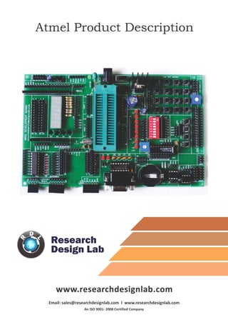
2. RESEARCH DESIGN LABS | VOLUME 1, ISSUE 1 WWW.RESEARCHDESIGNLAB.COM
All digital circuits require regulated power supply. Here is
a simple power supply circuit diagram used on this board.
You can use AC or DC source (12V) which converts into
regulated 5V which is required for driving the
developmentboard circuit.
Select the IC's from the given list and mount on the ZIF socket. ZIF socket pin maps out PORT1
PORT2 PORT3 PORT4 for easy making connections for the restof the circuit. Port 1 is enabled with
pull up circuit and also connected ISP for easy on board Programming.
1. Power supply, 5V-12V
1. 40 pin ZIF socket for IC mount & ISP connector*
NOTE: if you are following to on board program, the capacitor c1 should be desoldered and
removed from the port. You also need to know, if you remove the capacitor the board has to
reset manually by pressing the reset button s1 each time you burn a code.
3. Resets your microcontroller by pressing s1
NOTE: if you are following to on board
program, the capacitor c1 should be
desoldered and removed from the port.
You also need to know, if you remove the
capacitor the board has to reset manually
by pressing the reset button s1 each time
you burn a code.
2. Reset
Node connector is an additional on board
connection extender or 1 connection IN and
1 connection out
3. Node connector
One seven segment digit consist of 7+1 LEDs which are arranged in a specific formation which
can be used to represent digits from 0 to 9 and even some letters. One additional LED is used for
marking the decimal dot, in case you want to write a decimal point in the desired segment.
4. 4 digit 7 segment display
4. 26 Pin raspberry connector is an easy way
for making connections with raspberry pi
with this development board.
5. 26 pin raspberry connector 6. Arduino Shield footprint
Arduino Shield footprint is provided in the
board to mount different types of Arduino
compatible shields on this development
board.
IC ULN2803 consists of octal high voltage, high current darlington transistor arrays. The eight
NPN Darlington connected transistors in this family of arrays are ideally suited for interfacing
between low logic level digital circuitry (such as TTL, CMOS or PMOS/NMOS) and the higher
current/voltage requirements of lamps, relays, printer hammers or other similar loads for a
broad range of computer, industrial, and consumer applications.
7. ULN 2803 driver
· Eight Darlingtons with Common Emitter.
· Open–collector outputs.
· Free wheeling clamp diodes for
transient suppression.
Features
· Output Current to 500 mA.
· Output Voltage to 50 V.
· Inputs pinned opposite outputs to
simplify board layout.
5. The ULN 2803 IC consists of eight NPN Darlington
connected transistors (often called a Darlington
pair). Darlington pair consists of two bipolar
transistors such that the current amplified by the
first is amplified further by the second to get a
high current gain β or hFE. The figure shown below
is one of the eight Darlington pairs of ULN 2803 IC.
Now 2 cases arise:-
Case 1: When IN is 0 volts.
Q1 and Q2 both will not conduct as there is no base current provided to them. Thus, nothing will
appear at the output (OUT).
Case 2: When IN is 5 volts.
Input current will increase and both transistors Q1 and Q2 will begin to conduct. Now, input
current of Q2 is combination of input current and emitter current of Q1, so Q2 will conduct more
than Q1 resulting in higher current gain which is very much required to meet the higher current
requirements of devices like motors, relays etc. Output current flows through Q2 providing a path
(sink) to ground for the external circuit that the output is applied to. Thus, when a 5V input is
applied to any of the input pins (1 to 8), output voltage at corresponding output pin (11 to 18)
drops down to zero providing GND for the external circuit. Thus, the external circuit gets
grounded at one end while it is provided +Vcc at its other end. So, the circuit gets completed and
starts operating.
Working
6. One IC that wants to talk to another must: (Protocol)
1) Wait until it sees no activity on the I2C bus. SDAand SCLare both high. The bus is 'free'.
2) Put a message on the bus that says 'its mine' - I have STARTED to use the bus. All other ICs then
LISTEN to the bus data to see whether they might be the one who will be called up (addressed).
3) Provide on the CLOCK (SCL) wire a clock signal. It will be used by all the ICs as the reference
time at which each bit of DATA on the data (SDA) wire will be correct (valid) and can be used. The
data on the data wire (SDA) must be valid at the time the clock wire (SCL) switches from 'low' to
'high' voltage.
4) Put out in serial form the unique binary 'address'(name) of the IC that it wants to communicate
with.
5) Put a message (one bit) on the bus telling whether it wants to SEND or RECEIVE data from the
other chip. (The read/write wire is gone!)
6) Ask the other IC to ACKNOWLEDGE (using one bit) that it recognized its address and is ready to
communicate.
7)After the other IC acknowledges all is OK, data can be transferred.
8) The first IC sends or receives as many 8-bit words of data as it wants. After every 8-bit data
word the sending IC expects the receiving IC to acknowledge the transfer is going OK.
9) When all the data is finished the first chip must free up the bus and it does that by a special
message called 'STOP'. It is just one bit of information transferred by a special 'wiggling' of the
SDA/SCLwires of the bus.
1.I2C bus
7. Serial to Peripheral Interface (SPI) is a hardware/firmware communications protocol developed
by Motorola and later adopted by others in the industry. Microwire of National Semiconductor is
same as SPI. Sometimes SPI is also called a "four wire" serial bus.
The Serial Peripheral Interface or SPI-bus is a simple 4-wire serial communications interface used
by many microprocessor/microcontroller peripheral chips that enables the controllers and
peripheral devices to communicate each other. Even though it is developed primarily for the
communication between host processor and peripherals, a connection of two processors via SPI is
just as well possible.
The SPI bus, which operates at full duplex (means, signals carrying data can go in both directions
simultaneously), is a synchronous type data link setup with a Master / Slave interface and can
support up to 1 megabaud or 10Mbps of speed. Both single-master and multi-master protocols are
possible in SPI. But the multi-master bus is rarely used and look awkward, and are usually limited
to a single slave.
The SPI Bus is usually used only on the PCB. There are many facts, which prevent us from using it
outside the PCB area. The SPI Bus was designed to transfer data between various IC chips, at very
high speeds. Due to this high-speed aspect, the bus lines cannot be too long, because their
reactance increases too much, and the Bus becomes unusable. However, its possible to use the SPI
Bus outside the PCB at low speeds, but this is not quite practical.
The peripherals can be a Real Time Clocks, converters like ADC and DAC, memory modules like
EEPROM and FLASH, sensors like temperature sensors and pressure sensors, or some other devices
like signal-mixer, potentiometer, LCD controller, UART, CAN controller, USB controller and
amplifier.
1.SPI bus
8. All XBeeZNet 2.5 modules can be identified by their unique 64-bit addresses or a user-
configurableASCII string identifier The 64-bit address of a module can be read using the SH and SL
commands. TheASCII string identifier is configured using the NI command.
To transmit using device addressing, only the destination address must be configured. The
destination address can be specified using either the destination device's 64-bit address or its NI-
string. The XBee modules also support coordinator and broadcast addressing modes. Device
addressing in the AT firmware is configured using the DL, DH, or DN commands. In the API
firmware, the ZigBee Transmit Request API frame (0x10) can be used to specify destination
addresses.
To address a node by its 64-bit address, the destination address must be set to match the 64-bit
address of the remote. In the AT firmware, the DH and DL commands set the destination 64-bit
address. In the API firmware, the destination 64-bit address is set in the ZigBee Transmit Request
frame. ZigBee end devices rely on a parent (router or coordinator) to remain awake and receive
any data packets destined for the end device. When the end device wakes from sleep, it sends a
transmission (poll request) to its parent asking if the parent has received any RF data destined for
the end device. The parent, upon receipt of the poll request, will send an RF response and the
buffered data (if present). If the parent has no data for the end device, the end device may
return to sleep, depending on its sleep mode configuration settings. The following figure
demonstrates how the end device uses polling to receive RF data through its parent.
1.XBEE footprint/ XBEE Adaptor module
9. These connectors
provide on board 3.3V DC
connections.
A s t a n d a r d F T 2 3 2
breakout board from
researchdesignlab.com
could be used to interface
on these connectors,
whose other end is
connected to a USB.
RS-232 is a standard communication protocol for linking computer and its peripheral devices
to allow serial data exchange. In simple terms RS232 defines the voltage for the path used for
data exchange between the devices. It specifies common voltage and signal level, common
pin wire configuration and minimum, amount of control signals.
1.DB-9 female connector
11. FT232 breakout board connector
12. DC 3.3V connectors
10. 1. 8x1 LED's
LED's are used to indicate something, whether any pin is high or indicating the output for
many purposes like indicating I/O status or program debugging running state. We have
four led outputs on board which can be used by the programmer as per the requirement
for testing and development.
1. 8 way DIP switch
DIP switches are an alternative to jumper blocks. Their main advantages are that
they are quicker to change and there are no parts to lose.
11. 1. RTC Module
The DS1307 Serial Real Time Clock is a low power, full BCD clock/calendar plus 56 bytes
of nonvolatile SRAM. Address and data are transferred serially via a 2-wire bi-
directional bus. The clock/calendar provides seconds, minutes, hours, day, date,
month, and year information. The end of the month date is automatically adjusted for
months with less than 31 days, including corrections for leap year. The clock operates
in either the 24-hour or 12-hour format with AM/PM indicator. The DS1307 has a built-
in power sense circuit which detects power failures and automatically switches to the
battery supply.
OPERATION
The DS1307 operates as a slave device on the serial bus. Access is obtained by
implementing a START condition and providing a device identification code
followed by a register address. Subsequent registers can be accessed sequentially
until a STOP condition is executed. When VCC falls below 1.25 x VBAT the device
terminates an access in progress and resets the device address counter. Inputs to
the device will not be recognized at this time to prevent erroneous data from
being written to the device from an out of tolerance system. When VCC falls
below VBAT the device switches into a low current battery backup mode. Upon
power up, the device switches from battery to VCC when VCC is greater than VBAT
+0.2V and recognizes inputs.
Features:
1. 56 byte nonvolatile RAM for data
storage
2. 2-wire serial interface
3. Programmable square wave output
signal
4. Automatic power-fail detect and
switch circuitry
5. Consumes less than 500 nA in battery
backup mode with oscillator running
6. Optional industrial temperature range
-40°C to +85°C
7. Available in 8-pin DIP or SOIC
8. Recognized by Underwriters Laboratory
12. PIN DESCRIPTION
1. VCC - Primary Power Supply
2. X1, X2 - 32.768 kHz Crystal Connection
3. VBAT - +3V Battery Input
4. GND - Ground
1.EEPROM
IC, EEPROM I2C 4K, 24C04, DIP8
Memory Size: 4Kbit
Memory Configuration: 512 x 8
Interface Type: I2C, Serial
Clock Frequency: 400kHz
Supply Voltage Range: 2.5V to 5.5V
Memory Case Style: DIP
No. of Pins: 8
Operating Temperature Range: -40°C to +85°C
SVHC: No SVHC (19-Dec-2011)
Base Number: 24
Device Marking: M24C04
IC Generic Number: 24C04
Interface: I2C
Interface Type: Serial, I2C
Logic Function Number: 24C04
Memory Configuration: 512 x 8
Memory Size: 4Kbit
Memory Type: EEPROM
Memory Voltage Vcc: 2.5V
Operating Temperature Max: +85°C
Operating Temperature Min: -40°C
Package / Case: DIP
Supply Voltage Max: 5.5V
Supply Voltage Min: 2.5V
Termination Type: Through Hole
Voltage Vcc: 2.5V
5. SDA - Serial Data
6. SCL - Serial Clock
7. SQW/OUT - Square wave/Output Driver
13. 1. 2x5x2 jumper node
Node connector is an additional on board connection extender or 1
connection IN and 1 connection out
1. DC 5V connectors
These connectors provide
on board 5V DC
connections.
1. Analog to Digital output
Most of the signals directly encountered in science and engineering are continuous:
light intensity that changes with distance; voltage that varies over time; a chemical
reaction rate that depends on temperature, etc. Analog-to-Digital Conversion (ADC)
and Digital-to-Analog Conversion (DAC) are the processes that allow digital
computers to interact with these everyday signals. Digital information is different
from its continuous counterpart in two important respects: it is sampled, and it is
quantized. Both of these restrict how much information a digital signal can contain.
14. FUNCTIONAL DESCRIPTION
Addressing
Each PCF8591 device in an I2C-bus system is activated by sending a valid address
to the device. The address consists of a fixed part and a programmable part. The
programmable part must be set according to the address pins A0, A1 and A2. The
address is always sent as the first byte after the start condition in the I2C-bus
protocol. The last bit of the address byte is the read/write-bit which sets the direction
of the following data transfer.
D/A CONVERSION
The third byte sent to a PCF8591 device is stored in the DAC data register and is converted
to the corresponding analog voltage using the on-chip D/A converter. This D/A converter
consist of a resistor divider chain connected to the external reference voltage with 256
taps and selection switches. The tap decoder switches one of these taps to the DAC output
line. The analog output voltage is buffered by an auto-zeroed unity gain amplifier. Setting
the analog output enable flag of the control register switches this buffer amp on or off. In
the active state, the output voltage is held until a further data byte is sent. The on-chip
D/A converter is also used for successive approximation A/D conversion. In order to
release the DAC for an A/D conversion cycle the unity gain amplifier is equipped with a
track and hold circuit. This circuit holds the output voltage while executing the A/D
conversion.
A/D CONVERSION
The A/D converter uses the successive approximation conversion technique. The on-chip
D/A converter and a high-gain comparator are used temporarily during an A/D conversion
cycle. An A/D conversion cycle is always started after sending a valid read mode address to
a PCF8591 device. The A/D conversion cycle is triggered at the trailing edge of the
acknowledge clock pulse and is executed while transmitting the result of the previous
conversion Once a conversion cycle is triggered, an input voltage sample of the selected
channel is stored on the chip and is converted to the corresponding 8-bit binary code.
Samples picked up from differential inputs are converted to an 8-bit two's complement
code. The conversion result is stored in the ADC data register and awaits transmission. If the
auto-increment flag is set, the next channel is selected. The first byte transmitted in a read
cycle contains the conversion result code of the previous read cycle. After a POR condition,
the first byte read is 80h.The maximum A/D conversion rate is given by the actual speed of
the I2C-bus
15. PCF8951T
The PCF8591 is a single-chip, single-supply low-power 8-bit CMOS data acquisition device
with four analog inputs, one analog output and a serial I2C-bus interface. Three address
pins A0, A1 and A2 are used for programming the hardware address, allowing the use of up
to eight devices connected to the I2C-bus without additional hardware. Address, control
and data to and from the device are transferred serially via the two-line bidirectional I2C-
bus.The functions of the device include analog input multiplexing, on-chip track and hold
function, 8-bit analog-to-digital conversion and an 8-bit digital-to-analog conversion. The
maximum conversion rate is given by the maximum speed of the I2C-bus.
FEATURES
1. Single power supply
2. Operating supply voltage 2.5 V to 6.0 V
3. Low standby current
4. Serial input and output via I2C-bus
5. I2C address selection by 3 hardware address pins
6. Max sampling rate given by I2C-bus speed
7. 4 analog inputs configurable as single ended or
differential inputs
8. Auto-incremented channel selection
9. Analog voltage range from VSS to VDD
10. On-chip track and hold circuit
11. 8-bit successive approximation A/D conversion
12. Multiplying DAC with one analog output
Fig: PCF8951T IC
PIN DESCRIPSION
1-4. AIN0- AIN3:-analog inputs (A/D converter)
5-7. A0- A2:- hardware slave address
8. VSS: - ground supply voltage
9. SDA: - I2C-bus serial data input and output
10. SCL: - I2C-bus serial clock input
11. OSC: - oscillator input/output
12. EXT: - external/internal switch for oscillator input
13. AGND: - analog ground supply
14. VREF: - voltage reference input
15. AOUT: - analog output (D/A converter)
16. VDD: - supply voltage
16. 1. 4x1 keypad
Switches are mainly used to switch the controls of a module. We have four
switches on board which can be used by the programmer as per the
requirement for testing and development.
1. 16x2 LCD connectors
LCD screen consists of two lines with 16 characters each. Each character consists of
5x7 dot matrix. Contrast on display depends on the power supply voltage and
whether messages are displayed in one or two lines. For that reason, variable
voltage 0-Vdd is applied on pin marked as Vee. Trimmer potentiometer is usually
used for that purpose. Some versions of displays have built in backlight (blue or
green diodes). When used during operating, a resistor for current limitation should
be used (like with any LE diode). LCD Connection Depending on how many lines are
used for connection to the microcontroller, there are 8-bit and 4-bit LCD modes.
The appropriate mode is determined at the beginning of the process in a phase
called “initialization”. In the first case, the data are transferred through outputs
D0-D7 as it has been already explained. In case of 4-bit LED mode, for the sake of
saving valuable I/O pins of the microcontroller, there are only 4 higher bits (D4-D7)
used for communication, while other may be left unconnected.
Consequently, each data is sent to LCD in two steps: four higher bits are sent first
(that normally would be sent through lines D4-D7), four lower bits are sent
afterwards. With the help of initialization, LCD will correctly connect and interpret
each data received. Besides, with regards to the fact that data are rarely read from
LCD (data mainly are transferred from microcontroller to LCD) one more I/O pin
may be saved by simple connecting R/W pin to the Ground. Such saving has its
price. Even though message displaying will be normally performed, it will not be
possible to read from busy flag since it is not possible to read from display.
17. Features:
1. Can display 224 different symbols.
2. Low power consumption.
3. 5x7 dot matrix format.
4. Powerful command set and user produced characters.
Fig: Circuit connections of LCD
PIN DESCRIPTION
1. Gnd:- Power supply ground
2. VCC:-+5v Power supply input
3. RS:- Reset pin
4. R/W:- Read/Write pin
5. En:-Enable pin
6. D0-D7:- Data lines
18. 1. Node connector
Node connector is an additional on
board connection extender or 1
connection IN and 1 connection out
1. 4x4 Matrix Keypad
In a 4x4 matrix keypad eight Input/Output ports are used for interfacing with any
microcontrollers. Rows are connected to Peripheral Input/Output (PIO) pins configured as
output. Columns are connected to PIO pins configured as input with interrupts. In
thisconfiguration, four pull-up resistors must be added in order to apply a high level on
the corresponding input pins as shown in below Figure. The corresponding hexadecimal
value of the pressed key is sent on four LEDs.
WORKING
This Application Note describes programming techniques implemented on the AT91 ARM-
based microcontroller for scanning a 4x4 Keyboard matrix usually found in both
consumer and industrial applications for numeric data entry.AT91 Keyboard interface In
this application, a 4x4 matrix keypad requiring eight Input/Output ports for interfacing
is used as an example. Rows are connected to Peripheral Input/Output (PIO) pins
configured as output. Columns are connected to PIO pins configured as input with
interrupts. In this configuration, four pull-up resistors must be added in order to apply a
high level on the corresponding input pins as shown in Figure 1. The corresponding
hexadecimal value of the pressed key is sent on four LEDs.
19. FEATURES
1. Contact debouncing.
2. Easy to interface.
3. Interfaces to any microcontroller or microprocessor.
4. Data valid output signal for interrupt activation.
1.DC 12V connectors
These connectors provide on board 12V DC connections.
PIN DETAILS
pin 1-4: R0-R3:- Rows
pin 5-8: C0-C3:- Columns