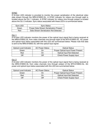
Download to read offline

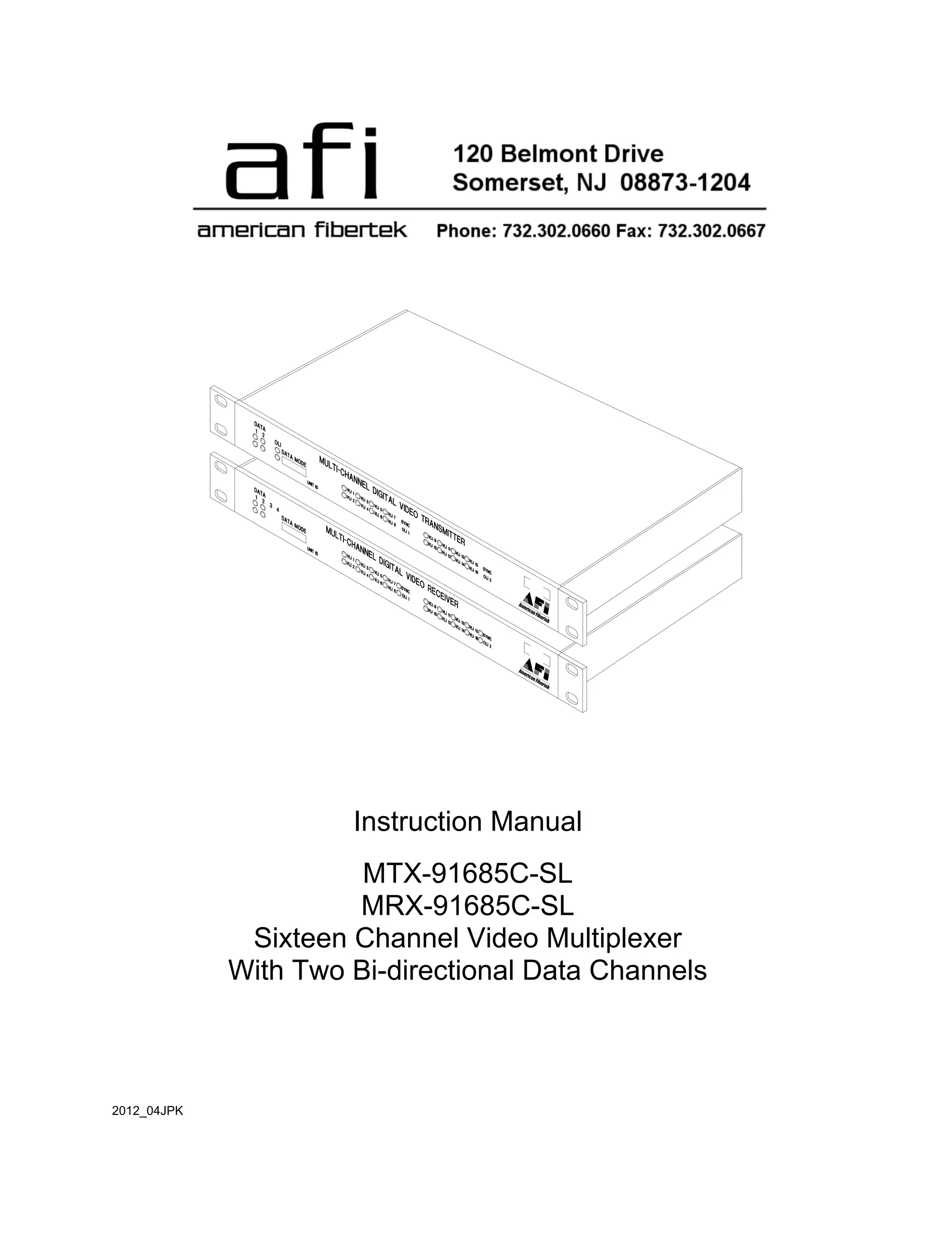
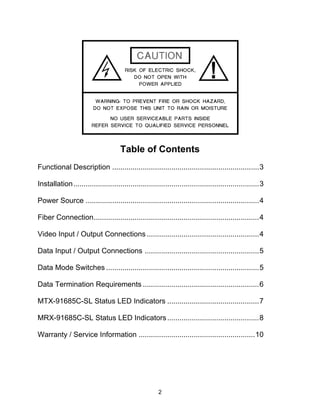

The document is an instruction manual for the American Fibertek series 91685c-sl multimode sixteen channel video multiplexer, detailing installation, connection, and operation procedures. It outlines how the unit transmits sixteen video signals and bi-directional data over fiber optic cable and includes configurations for various data modes. Additionally, it includes warranty and service information alongside operational instructions for both the transmitter and receiver units.


