


![• Pengembang menarik penetran dari cacat keluar
ke permukaan untuk membentuk indikasi yang
terlihat, umumnya dikenal sebagai berdarah-out.
Setiap daerah yang berdarah-out dapat
menunjukkan lokasi, orientasi dan jenis
kemungkinan cacat di permukaan. Menafsirkan
hasil dan karakterisasi cacat dari indikasi yang
ditemukan mungkin membutuhkan beberapa
pelatihan dan / atau pengalaman [ukuran indikasi
bukan ukuran sebenarnya dari cacat]](https://image.slidesharecdn.com/assetintegritymanagementsystem-book-240923013815-9c282f66/85/ASSET-INTEGRITY-MANAGEMENT-SYSTEM-BOOK-pptx-137-320.jpg)


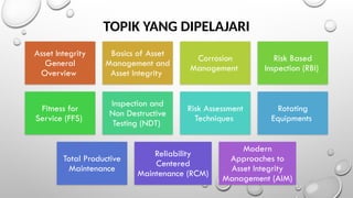
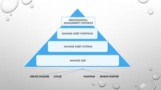
The document outlines a training program focused on asset integrity management, detailing strategies for optimizing asset integrity systems, risk-based inspection methodologies, and maintenance practices. It covers topics such as corrosion management, fitness for service assessment, and inspection techniques, emphasizing the importance of effective asset management throughout the asset lifecycle. Participants will learn to identify threats, enhance productivity, and implement technical approaches to improve operational outcomes and prolong facility life.


![[RBI] course 1 framework](https://cdn.slidesharecdn.com/ss_thumbnails/rbicourse1framework-121022102531-phpapp02-thumbnail.jpg?width=640&height=640&fit=bounds)


