Download as PDF, PPTX
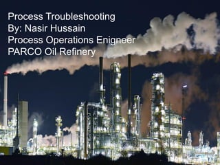


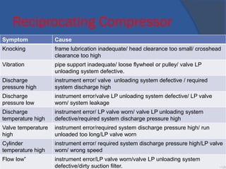
![Mind Mapping
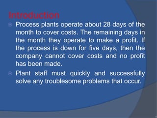
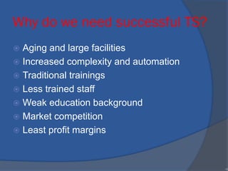
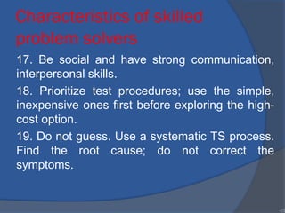
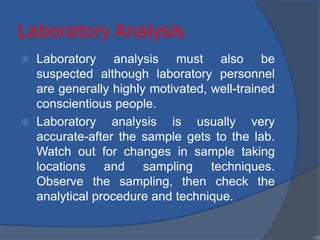
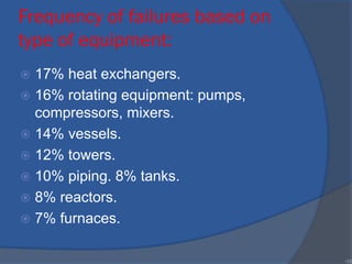
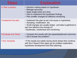
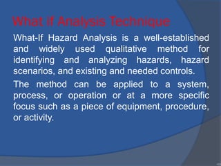
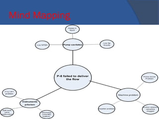
A mind map is a diagram used to visually
organize information. A mind map is
hierarchical and shows relationships among
pieces of the whole.[1] It is often created
around a single concept, drawn as an image
in the center of a blank page, to which
associated representations of ideas such as
images, words and parts of words are added.
Major ideas are connected directly to the
central concept, and other ideas branch out
from those major ideas.
•73](https://image.slidesharecdn.com/opt-converted-180918172427/85/Process-Troubleshooting-73-320.jpg)


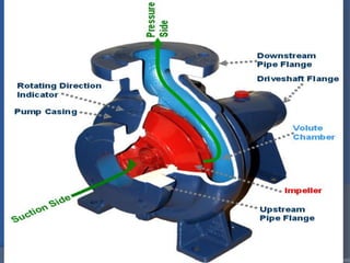
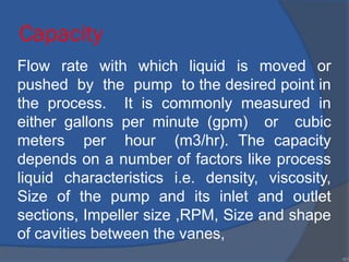
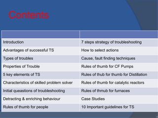
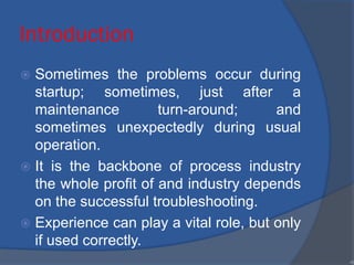
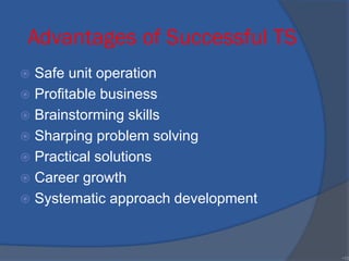
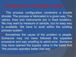
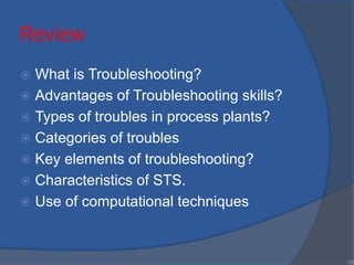
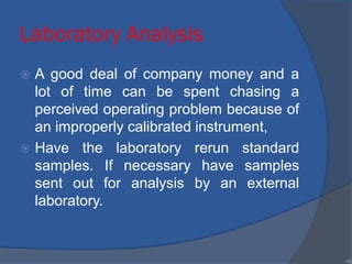
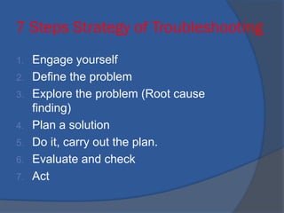
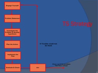
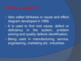
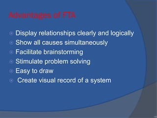
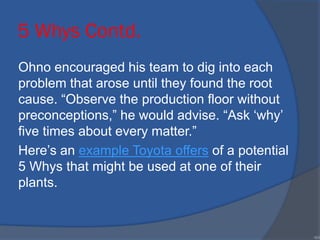
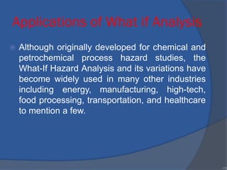
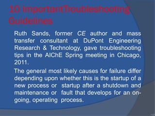
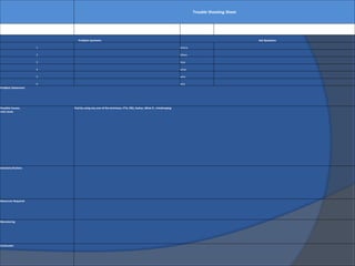
![Centrifugal Pumps TS Rules
of Thumb
Symptoms Control measures
No liquid
delivery
instrument error/not primed/ cavitation/supply tank
empty
Liquid
flowrate low
instrument error/ cavitation/ non-condensibles in
liquid/ inlet strainer clogged.
Intermittent
operation
[cavitation]*/ not primed/ non-condensibles in
liquid
Discharge
pressure low
instrument error/ noncondensibles in liquid/ speed
too low/ wrong direction of rotation
Power
demand
excessive
Speed too high/ density liquid high/ required
system head lower than expected/ viscosity high
•92](https://image.slidesharecdn.com/opt-converted-180918172427/85/Process-Troubleshooting-92-320.jpg)
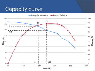

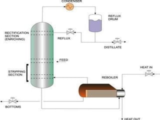
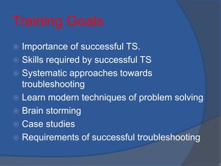
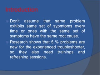
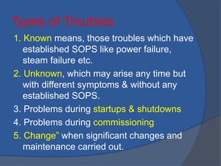
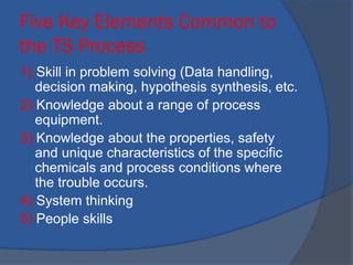
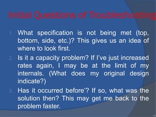
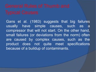
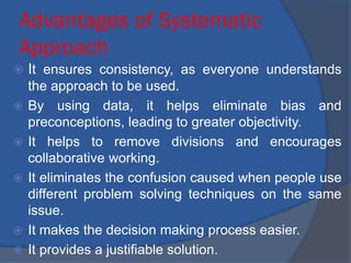
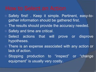
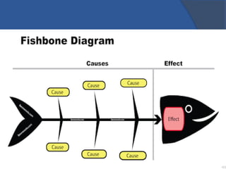
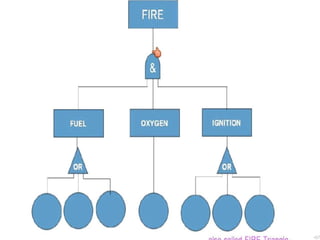
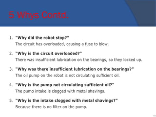
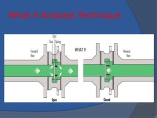
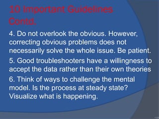
![Rules of thumb for Distillation
Column
Symptoms Causes
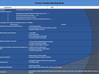
bottoms pressure>design High level in column, instrument faults, low
boiling rate of liquid
DT across column<design Feed and reflux composition change,
leakage from feed and product
exchangers, steam to reboiler stops or
restricted
Dp across the column<design instrument fault/ [low boilup rate], dry
trays/ low feedrate/ feed temperature too
high.
Feed flowrate<design instrument fault/ pump problems, filter
plugged/ column pressure>design/ feed
location higher than design.
Temperature of feed>design instrument fault/ preheater fouled/ feed
flowrate low/ heating medium
temperature<design
Temperature of bottoms<design instrument fault/ [low boilup]* loss of•99](https://image.slidesharecdn.com/opt-converted-180918172427/85/Process-Troubleshooting-99-320.jpg)
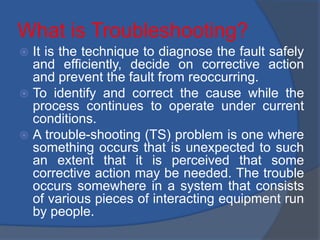
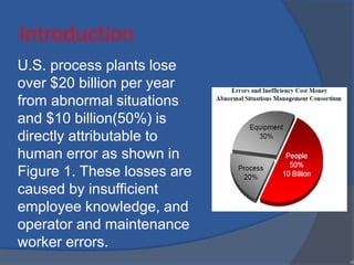
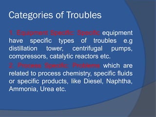
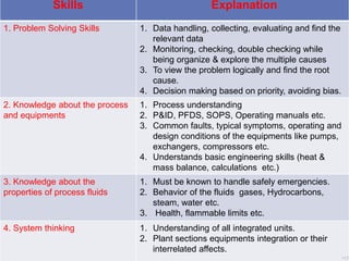
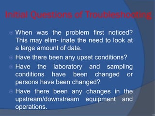
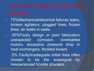
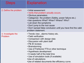
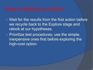
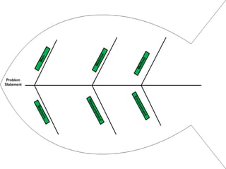
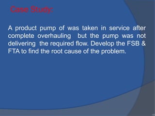
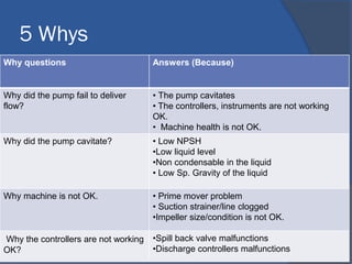
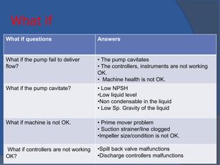
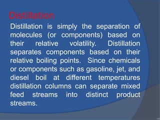
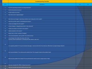
![Rules of thumb for Distillation
Column
Symptoms Causes
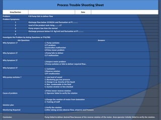
Temperature of
bottoms>design
Instrument fault/ [column pressure>design]*/ high boilup/
overhead condenser vent plugged/ insufficient condensing
Temperature at
top>design
Instrument fault/ bottom temperature>design/ reflux too low/
distillate feed forward too high/ column pressure high/ [flooding
Temperature at
top>design and
overhead composition
contaminated with too
many heavies”
vapor bypassing caused by excessive vapor velocities (high
boilup) or not enough liquid on tray or packing, or downcomers
not sealed, or sieve holes corroded larger than design and tray
weeps/ reflux too low/ feed contains excessive heavies
Temperature at
top<design
instrument fault/ control temperature too low/ [low boilup]
•100](https://image.slidesharecdn.com/opt-converted-180918172427/85/Process-Troubleshooting-100-320.jpg)
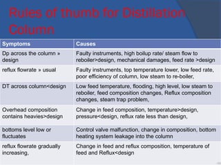
![Rules of thumb for Distillation
Column
All temperatures falling
simultaneously
low boilup pressure rising
Overhead off spec Poor tray or packing efficiency/ [maldistribution]*/ not
enough trays or packing/ loss of efficiency/ high
concentration of non-condensibles/ missing tray/ collapsed
tray/ liquid entrainment/ liquid bypass and weeping/ liquid
or gas maldistribution
Overhead contaminated
with heavies and excessive
reflux rate and high boilup
rate
inadequate gas-liquid contact/ insufficient liquid
disengagement from vapor/ presence of non-condensibles
in feed. “Overhead and bottoms off spec and decreases
across column in both DT and Dp
Overhead and bottoms off
spec
Bypass open on reflux control valve, poor stripping, low
flow of stripping agent
Overhead and bottoms off
spec, decrease in DT
across column and
Poor tray or packing efficiency/ [maldistribution]*/ not
enough trays or packing/ loss of efficiency/ high
concentration of non-condensibles/ missing tray/ collapsed•101](https://image.slidesharecdn.com/opt-converted-180918172427/85/Process-Troubleshooting-101-320.jpg)

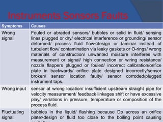
![Control Valve Faults
Symptoms Causes
Leaks Erosion/ corrosion/ gaskets, packing or bolts at temperatures, pressures
and fluids that differ from design
Can’t control
low flowrate
miscalibration/ buildup of rust, scale, dirt/[faulty design]*.
Can’t stop
flow
miscalibration/ damaged seat or plug
Excessive
flow
miscalibration/ damaged seat or plug
Slow
response
Restricted air to actuator/ dirty air filters. “Noise”: cavitation/
compressible flow
Poor valve
action
Dirt in instrument air/ sticky valve stem/ packing gland too tight/ faulty
valve positioner
Cycling Stiction. [Faulty design]*: valve stem at design flowrate is not at
midrange. [Stiction]* is the sticking and friction related to valve
movement and measured as the difference between the driving values
needed to overcome static friction upscale and downscale. Likely cause
•105](https://image.slidesharecdn.com/opt-converted-180918172427/85/Process-Troubleshooting-105-320.jpg)
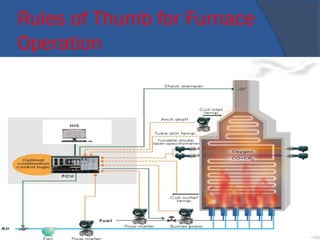
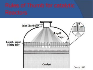
![Rules of Thumb for catalytic
ReactorsSymptoms Causes
DP
higher>design
catalyst degradation/ instrument error/ high gas flow/ sudden coking/
problem left in from construction or revamp, internal damage
Rapid decline in
conversion
unfavorable shift in equilibrium at operating temperature, for
exothermic reactions/ [sintering]*/ [agglomeration], poisons in feed,
temperature runaway
Gradual decline
in conversion
Sample error/ analysis error/ temperature sensor error/ [catalyst
activity lost]*/ [maldistribution]*/ [unacceptable temperature profiles]*/
[inadequate heat transfer]*/ wrong locations of feed, discharge or
recycle lines/ faulty design of feed and discharge ports/ wrong
internal baffles and internals/ faulty bed-voidage profiles
Temperature
runaways
Change in feed composition, furnace controlled firing, uncontrolled
reactions. feed temperature too high/ [temperature hot spot]*/ cooling
water too hot, failure of cooling media
Local high
temperature/hot
spot
[misdistribution of gas flow]*/ instrument error/ extraneous feed
component that reacts exothermically
•116](https://image.slidesharecdn.com/opt-converted-180918172427/85/Process-Troubleshooting-116-320.jpg)
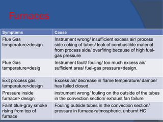
![Catalytic Reactors
Local low temperature
within the bed
[maldistribution of gas flow]*/ instrument error/ extraneous
feed component that reacts endothermically
Exit gas temperature too
high
instrument error/ control-system malfunction/ fouled reactor
coolant tubes.
Temperature varies axially
across bed
[maldistribution}
Symptom: Soon after startup, temperature of tubewall near top>usual and increasing
and perhaps Dp increase and less conversion than expected or operating
temperatures>usual to obtain expected conversion
Cause: inadequate catalyst regeneration/ contamination in feed; for steam reforming
sulfur concentration>specifications/ wrong feed composition; for steam reforming:
steam/CH4<7 to 10
•117](https://image.slidesharecdn.com/opt-converted-180918172427/85/Process-Troubleshooting-117-320.jpg)
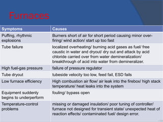
![Startup after Catalyst
Replacement/Regeneration
Symptoms Causes
conversions<standard Reduction faulty, bad batch of catalyst/
preconditioning of catalyst faulty/ temperature and
pressures incorrectly set/ instrument error for
pressure or temperature
poor selectivity bad batch of catalyst/ preconditioning of catalyst
faulty/ temperature and pressures incorrectly set/
instrument error for pressure or temperature
Dp<expected and
conversion<standard
maldistribution and axial variation in temperature/
larger size catalyst.
conversion<standard and Dp
increasing
maldistribution and axial temperatures different]*/
feed precursors present for polymerization or coking
Dp for this batch of
catalyst>previous batch
catalyst fines produced during loading/ poor loading
conversion<specifications per
unit mass of catalyst and more
side reactions
maldistribution/ faulty inlet distributor/ faulty exit
distributor
•118](https://image.slidesharecdn.com/opt-converted-180918172427/85/Process-Troubleshooting-118-320.jpg)
![Startup after Catalyst
Replacement/Regeneration
increased side reactions and
conversion<specification
Catalyst loading not the same in all tubes.
Active species volatized [regeneration faulty]*/ faulty catalyst design for typical
reaction temperature/ [hot spots]*.
Agglomeration of packing or
catalyst particles
[temperature hot spots
Carbon buildup inadequate regeneration]*/ [excessive carbon formed]*.
[Catalyst selectivity changes]*: [poisoned catalyst]*/
feed contaminants/ change in feed/ change in
temperature settings
Catalyst activity lost carbon buildup]*/[regeneration faulty]*/ [sintered
catalyst]*/ excessive regeneration temperature/
[poisoned catalyst]*/ [loss of surface area]*/
[agglomeration]*/ [active species volatized
Excessive carbon formed operating intensity above usual/ feed changes/
temperature hot spots. •119](https://image.slidesharecdn.com/opt-converted-180918172427/85/Process-Troubleshooting-119-320.jpg)
![Rules of Thumb for reactors
Symptoms Causes
Dust or corrosive
products from
upstream processes
in-line filters not working or not installed/ dust in the atmosphere
brought in with air/ air filters not working or not installed.
Loss of surface area [sintered catalyst]*/ [carbon buildup]*/ [agglomeration
Maldistribution faulty flow-distributor design/ plugging of flow distributors with fine
solids, sticky byproducts or trace polymers/ [sintered catalyst
particles]*/ [agglomeration of packing or catalyst particles]*/ fluid
feed velocity too high/ faulty loading of catalyst bed/ incorrect flow
collector at outlet.
Poisoned catalyst Poisons in feed/ flowrate of “counterpoison” insufficient/ poison
formed from unwanted reactions.
Reactor instability Control fault/ poor controller tuning/ wrong type of control/
insufficient heat transfer area/ feed temperature exceeds
threshold/ coolant temperature exceeds threshold/ coolant
flowrate<threshold/ tube diameter too large
•120](https://image.slidesharecdn.com/opt-converted-180918172427/85/Process-Troubleshooting-120-320.jpg)
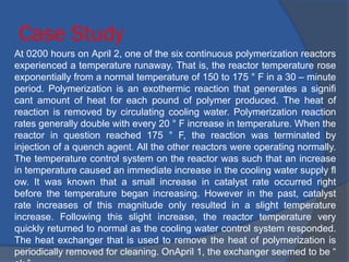


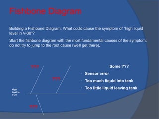
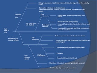
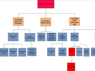
The document discusses troubleshooting processes in process operations, highlighting its importance, methodologies, and skills required for effective problem-solving in oil refineries. It outlines a systematic approach consisting of seven key steps and emphasizes the need for effective communication, data handling, and safety in troubleshooting. The document also covers different types of troubles, their causes, guidelines for successful troubleshooting, and various techniques to analyze and resolve issues.


