8085 Architecture &
ItsAssembly language programming
PRESENTED BY: GROUP-03
MEMBERS:
• S u m a i a I s l a m Ta j ( 2 0 C S E 0 3 4 )
• M u a a z B i n Z a h i d ( 2 0 C S E 0 3 9 )
• R a s h e d u l I s l a m ( 2 0 C S E 0 4 7 )
• D e e p a n w i t a R o y ( 2 0 C S E 0 2 4 )
• N u r e H a f s a S h e f a ( 2 0 C S E 0 1 8 )
• A b d u l l a h A l M a h i n ( 2 0 C S E 0 3 1 )
• M d . S a i f u z z a m a n A b h i ( 2 0 C S E 0 5 2 )
• S a r a b a r Ta h u r a ( 2 0 C S E 0 2 9 )
• N a h i d F o r h a d ( 2 0 C S E 0 2 0 )
PR ES EN T ED TO :
D r. Ta n i a I s l a m
A s s i s t a n t
P r o f e s s o r, D e p t o f
C S E , U n i v e r s i t y o f
B a r i s h a l
2.
Outline
• 8085 Eraand Features
• 8085
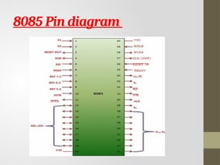
• Pin diagram
• Block diagram (Data Path)
• Bus Structure
• Register Structure
• Instruction Set of 8085
• Sample program of 8085
• Simulator & Kit for 8085
3.
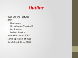
8085 Microprocessor
• 8Bit CPU
• 3-6Mhz
• Simpler design: Single Cycle CPU
• 40 Pin Dual line Package
• 16 bit address
• 6 registers: B, C, D, E, H,L
• Accumulator 8 bit
Note: Architecture of 8085 microprocessor - GeeksforGeeks
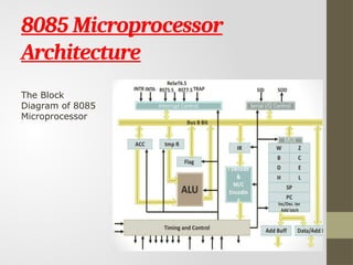
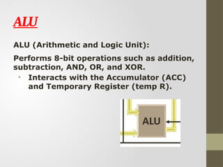
ALU
ALU (Arithmetic andLogic Unit):
Performs 8-bit operations such as addition,
subtraction, AND, OR, and XOR.
• Interacts with the Accumulator (ACC)
and Temporary Register (temp R).
7.
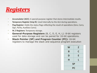
Registers
• Accumulator (ACC):A special-purpose register that stores intermediate results.
• Temporary Register (tmp R): Used internally by the ALU during operations.
• Flag Register: Holds the status flags reflecting the result of operations (Zero, Carry,
Sign, Parity, Auxiliary Carry).
• W, Z Registers: Temporary storage.
• General-Purpose Registers (B, C, D, E, H, L): 8-bit registers
used for data storage and can be paired for 16-bit operations.
• Stack Pointer (SP) and Program Counter (PC): 16-bit
registers to manage the stack and sequence program execution
8.
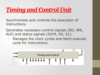
Timing and ControlUnit
Synchronizes and controls the execution of
instructions.
Generates necessary control signals (RD, WR,
ALE) and status signals (IO/M, S0, S1).
• Manages the clock cycles and fetch-execute
cycle for instructions.
9.
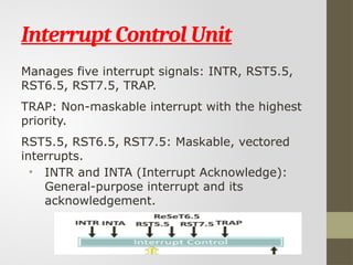
Interrupt Control Unit
Managesfive interrupt signals: INTR, RST5.5,
RST6.5, RST7.5, TRAP.
TRAP: Non-maskable interrupt with the highest
priority.
RST5.5, RST6.5, RST7.5: Maskable, vectored
interrupts.
• INTR and INTA (Interrupt Acknowledge):
General-purpose interrupt and its
acknowledgement.
10.
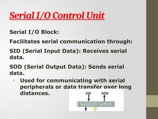
Serial I/O ControlUnit
Serial I/O Block:
Facilitates serial communication through:
SID (Serial Input Data): Receives serial
data.
SOD (Serial Output Data): Sends serial
data.
• Used for communicating with serial
peripherals or data transfer over long
distances.
11.
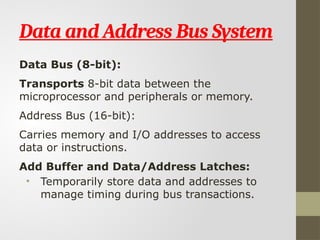
Data and AddressBus System
Data Bus (8-bit):
Transports 8-bit data between the
microprocessor and peripherals or memory.
Address Bus (16-bit):
Carries memory and I/O addresses to access
data or instructions.
Add Buffer and Data/Address Latches:
• Temporarily store data and addresses to
manage timing during bus transactions.
12.
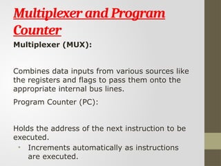
Multiplexer and Program
Counter
Multiplexer(MUX):
Combines data inputs from various sources like
the registers and flags to pass them onto the
appropriate internal bus lines.
Program Counter (PC):
Holds the address of the next instruction to be
executed.
• Increments automatically as instructions
are executed.
13.
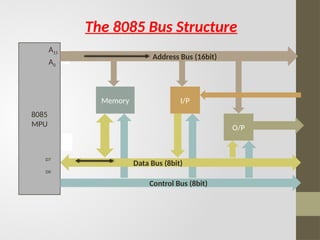
The 8085 BusStructure
8085
MPU
A15
A0
D0
D7
Address Bus (16bit)
Memory I/P
Data Bus (8bit)
O/P
Control Bus (8bit)
14.
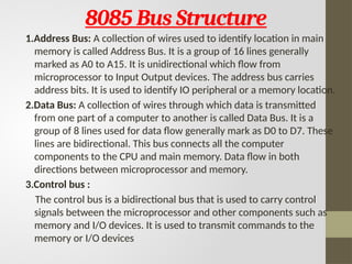
8085 Bus Structure
1.AddressBus: A collection of wires used to identify location in main
memory is called Address Bus. It is a group of 16 lines generally
marked as A0 to A15. It is unidirectional which flow from
microprocessor to Input Output devices. The address bus carries
address bits. It is used to identify IO peripheral or a memory location.
2.Data Bus: A collection of wires through which data is transmitted
from one part of a computer to another is called Data Bus. It is a
group of 8 lines used for data flow generally mark as D0 to D7. These
lines are bidirectional. This bus connects all the computer
components to the CPU and main memory. Data flow in both
directions between microprocessor and memory.
3.Control bus :
The control bus is a bidirectional bus that is used to carry control
signals between the microprocessor and other components such as
memory and I/O devices. It is used to transmit commands to the
memory or I/O devices
15.
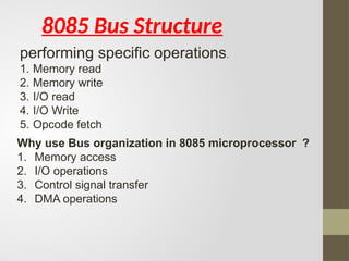
8085 Bus Structure
performingspecific operations.
1. Memory read
2. Memory write
3. I/O read
4. I/O Write
5. Opcode fetch
Why use Bus organization in 8085 microprocessor ?
1. Memory access
2. I/O operations
3. Control signal transfer
4. DMA operations
16.
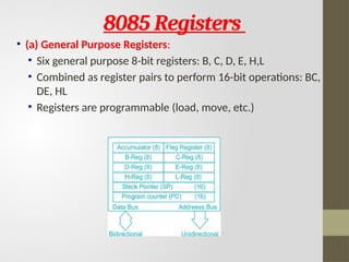
8085 Registers
• (a)General Purpose Registers:
• Six general purpose 8-bit registers: B, C, D, E, H,L
• Combined as register pairs to perform 16-bit operations: BC,
DE, HL
• Registers are programmable (load, move, etc.)
17.
Register1
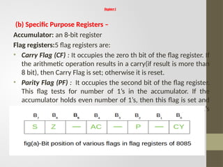
(b) Specific PurposeRegisters –
Accumulator: an 8-bit register
Flag registers:5 flag registers are:
• Carry Flag (CF) : It occupies the zero th bit of the flag register. If
the arithmetic operation results in a carry(if result is more than
8 bit), then Carry Flag is set; otherwise it is reset.
• Parity Flag (PF) : It occupies the second bit of the flag register.
This flag tests for number of 1’s in the accumulator. If the
accumulator holds even number of 1’s, then this flag is set and
it is said to even parity. On the other hand if the number of 1’s
is odd, then it is reset and it is said to be odd parity.
18.
Register 2
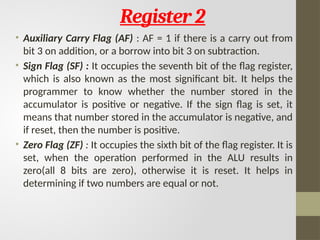
• AuxiliaryCarry Flag (AF) : AF = 1 if there is a carry out from
bit 3 on addition, or a borrow into bit 3 on subtraction.
• Sign Flag (SF) : It occupies the seventh bit of the flag register,
which is also known as the most significant bit. It helps the
programmer to know whether the number stored in the
accumulator is positive or negative. If the sign flag is set, it
means that number stored in the accumulator is negative, and
if reset, then the number is positive.
• Zero Flag (ZF) : It occupies the sixth bit of the flag register. It is
set, when the operation performed in the ALU results in
zero(all 8 bits are zero), otherwise it is reset. It helps in
determining if two numbers are equal or not.
19.
Register 3
(c) MemoryRegisters – There are two 16-bit registers used to
hold memory addresses.
• Program Counter: This register is used to sequence the
execution of the instructions.
• Stack Pointer: It is used as a memory pointer. It points to a
memory location in read/write memory, called the stack.
20.
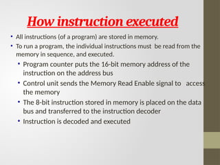
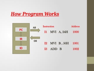
How instruction executed
•All instructions (of a program) are stored in memory.
• To run a program, the individual instructions must be read from the
memory in sequence, and executed.
• Program counter puts the 16-bit memory address of the
instruction on the address bus
• Control unit sends the Memory Read Enable signal to access
the memory
• The 8-bit instruction stored in memory is placed on the data
bus and transferred to the instruction decoder
• Instruction is decoded and executed
21.
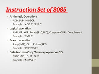
Instruction Set of8085
• Arithmetic Operations
• ADD, SUB, INR/DCR
• Example :’ ADD B’, ‘SUB C’
• Logical operation
• AND, OR, XOR, Rotate(RLC,RRC), Compare(CMP), Complement.
• Example : ‘CMP E’
• Branch operation
• Jump(JMP), CALL, Return(RET)
• Example : ‘JMP 2000H’
• Data transfer/Copy/Memory operation/IO
• MOV, MVI, LD, ST, OUT
• Example : ‘MOV A,B’
22.
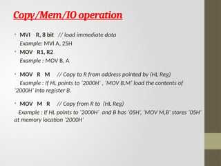
Copy/Mem/IO operation
• MVIR, 8 bit // load immediate data
Example: MVI A, 25H
• MOV R1, R2
Example : MOV B, A
• MOV R M // Copy to R from address pointed by (HL Reg)
Example : If HL points to ‘2000H’ , ‘MOV B,M’ load the contents of
‘2000H’ into register B.
• MOV M R // Copy from R to (HL Reg)
Example : If HL points to ‘2000H’ and B has ‘05H’, ‘MOV M,B’ stores ‘05H’
at memory location ‘2000H’
23.
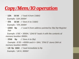
Copy/Mem/IO operation
• LDA16 bit // load A from (16bit)
Example: ‘LDA 2000H’
• STA 16 bit // Store A to (16bit)
Example : ‘STA 2000H’
• LDAX Rp // Load A from address pointed by (Rp) Rp=Register
Pair
Example : If BC = 3000H, ‘LDAX B’ loads A with the contents of
memory location 3000H.
• STAX Rp // Store A to (Rp)
Example : If DE = 4000H and A = 0AH, ‘STAX D’ stores 0AH at
memory location 4000H.
• LXI Rp 16bit // load immediate to Rp
Example : ‘LXI H, 3000H’
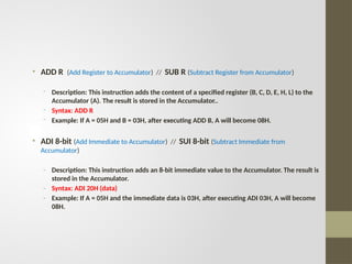
• ADD R(Add Register to Accumulator) // SUB R (Subtract Register from Accumulator)
- Description: This instruction adds the content of a specified register (B, C, D, E, H, L) to the
Accumulator (A). The result is stored in the Accumulator..
- Syntax: ADD R
- Example: If A = 05H and B = 03H, after executing ADD B, A will become 08H.
• ADI 8-bit (Add Immediate to Accumulator) // SUI 8-bit (Subtract Immediate from
Accumulator)
- Description: This instruction adds an 8-bit immediate value to the Accumulator. The result is
stored in the Accumulator.
- Syntax: ADI 20H (data)
- Example: If A = 05H and the immediate data is 03H, after executing ADI 03H, A will become
08H.
26.
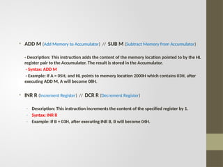
• ADD M(Add Memory to Accumulator) // SUB M (Subtract Memory from Accumulator)
- Description: This instruction adds the content of the memory location pointed to by the HL
register pair to the Accumulator. The result is stored in the Accumulator.
- Syntax: ADD M
- Example: If A = 05H, and HL points to memory location 2000H which contains 03H, after
executing ADD M, A will become 08H.
• INR R (Increment Register) // DCR R (Decrement Register)
- Description: This instruction increments the content of the specified register by 1.
- Syntax: INR R
- Example: If B = 03H, after executing INR B, B will become 04H.
27.
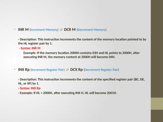
• INR M(Increment Memory) // DCR M (Decrement Memory)
- Description: This instruction increments the content of the memory location pointed to by
the HL register pair by 1.
- Syntax: INR M
- Example: If the memory location 2000H contains 03H and HL points to 2000H, after
executing INR M, the memory content at 2000H will become 04H.
• INX Rp (Increment Register Pair) // DCX Rp (Decrement Register Pair)
- Description: This instruction increments the content of the specified register pair (BC, DE,
HL, or SP) by 1.
- Syntax: INX Rp
- Example: If HL = 2000H, after executing INX H, HL will become 2001H.
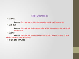
Logic Operations
• ANAR
Example: If A = 0AH and B = 03H, after executing ANA B, A will become 02H
• ANI 8bit
Example: If A = 0AH and the immediate value is 03H, after executing ANI 03H, A will
become 02H
• ANA M
Example: If A = 0AH and the memory location pointed to by HL contains 03H, after
executing ANA M, A will become 02H.
• ORA, ORI, XRA, XRI
30.
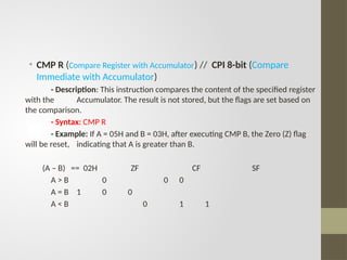
• CMP R(Compare Register with Accumulator) // CPI 8-bit (Compare
Immediate with Accumulator)
- Description: This instruction compares the content of the specified register
with the Accumulator. The result is not stored, but the flags are set based on
the comparison.
- Syntax: CMP R
- Example: If A = 05H and B = 03H, after executing CMP B, the Zero (Z) flag
will be reset, indicating that A is greater than B.
(A – B) == 02H ZF CF SF
A > B 0 0 0
A = B 1 0 0
A < B 0 1 1
31.
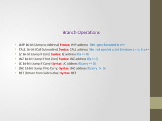
Branch Operations
• JMP16-bit (Jump to Address) Syntax: JMP address like : goto keyword in c++
• CALL 16-bit (Call Subroutine) Syntax: CALL address like : int sum(int a, int b) return a + b; in c++
• JZ 16-bit (Jump if Zero) Syntax: JZ address if(a == 0)
• JNZ 16-bit (Jump if Not Zero) Syntax: JNZ address if(a != 0)
• JC 16-bit (Jump if Carry) Syntax: JC address if(carry == 0)
• JNC 16-bit (Jump if No Carry) Syntax: JNC address if(carry != 0)
• RET (Return from Subroutine) Syntax: RET
32.
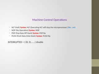
Machine Control Operations
•HLT (Halt) Syntax: HLT (Executing HLT will stop the microprocessor.) like : exit
• NOP (No Operation) Syntax: NOP
• POP (Pop Data Off Stack) Syntax: POP Rp
• PUSH (Push Data Onto Stack) Syntax: PUSH Rp
INTERRUPTED = ( DI, EI…….) disable
33.
Instruction Address
I1 MVIA, 24H 1000
I2 MVI B , 56H 1001
I3 ADD B 1002
PC
IR
ID
AB
DB
How Program Works
34.
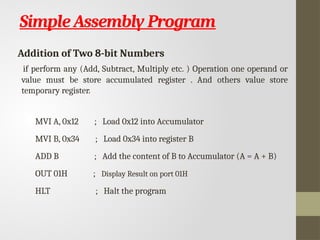
Simple Assembly Program
Additionof Two 8-bit Numbers
if perform any (Add, Subtract, Multiply etc. ) Operation one operand or
value must be store accumulated register . And others value store
temporary register.
MVI A, 0x12 ; Load 0x12 into Accumulator
MVI B, 0x34 ; Load 0x34 into register B
ADD B ; Add the content of B to Accumulator (A = A + B)
OUT 01H ; Display Result on port 01H
HLT ; Halt the program
35.
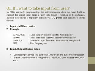
Q1: If Iwant to take input from user?
In 8085 assembly programming, the microprocessor does not have built-in
support for direct input from a user (like Scanf() function in C langauge).
Instead, user input is typically handled via I/O ports that connect to input
devices.
1. Input via IN Instruction
2. Example:
MVI A, 00H ; Load the port address into the Accumulator
IN 00H ; Read data from port 00H into the Accumulator
MOV B, A ; Move the input data from Accumulator to register B
HLT ; Halt the program
3. Input/Output Devices Setup
Connect input device to a particular I/O port on the 8085 microprocessor.
Ensure that the device is mapped to a specific I/O port address (00H, 01H
etc.)
36.
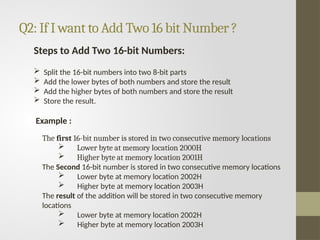
Q2: If Iwant to Add Two 16 bit Number ?
Steps to Add Two 16-bit Numbers:
Split the 16-bit numbers into two 8-bit parts
Add the lower bytes of both numbers and store the result
Add the higher bytes of both numbers and store the result
Store the result.
Example :
The first 16-bit number is stored in two consecutive memory locations
Lower byte at memory location 2000H
Higher byte at memory location 2001H
The Second 16-bit number is stored in two consecutive memory locations
Lower byte at memory location 2002H
Higher byte at memory location 2003H
The result of the addition will be stored in two consecutive memory
locations
Lower byte at memory location 2002H
Higher byte at memory location 2003H
37.
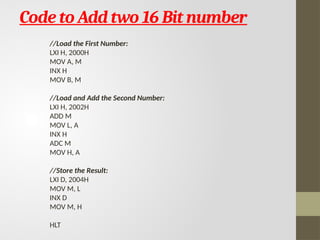
Code to Addtwo 16 Bit number
//Load the First Number:
LXI H, 2000H
MOV A, M
INX H
MOV B, M
//Load and Add the Second Number:
LXI H, 2002H
ADD M
MOV L, A
INX H
ADC M
MOV H, A
//Store the Result:
LXI D, 2004H
MOV M, L
INX D
MOV M, H
HLT
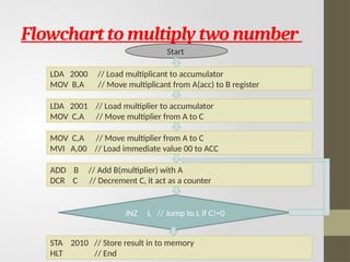
Flowchart to multiplytwo number
Start
LDA 2000 // Load multiplicant to accumulator
MOV B,A // Move multiplicant from A(acc) to B register
LDA 2001 // Load multiplier to accumulator
MOV C,A // Move multiplier from A to C
MOV C,A // Move multiplier from A to C
MVI A,00 // Load immediate value 00 to ACC
ADD B // Add B(multiplier) with A
DCR C // Decrement C, it act as a counter
JNZ L // Jump to L if C!=0
STA 2010 // Store result in to memory
HLT // End
40.
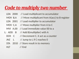
Code to multiplytwo number
LDA 2000 // Load multiplicant to accumulator
MOV B,A // Move multiplicant from A(acc) to B register
LDA 2001 // Load multiplier to accumulator
MOV C,A // Move multiplier from A to C
MVI A,00 // Load immediate value 00 to a
L: ADD B // Add B(multiplier) with A
DCR C // Decrement C, it act as a counter
JNZ L // Jump to L if C reaches 0
STA 2010 // Store result in to memory
HLT // End
41.
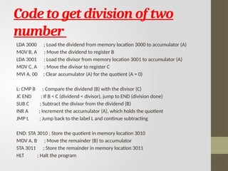
Code to getdivision of two
number
LDA 3000 ; Load the dividend from memory location 3000 to accumulator (A)
MOV B, A ; Move the dividend to register B
LDA 3001 ; Load the divisor from memory location 3001 to accumulator (A)
MOV C, A ; Move the divisor to register C
MVI A, 00 ; Clear accumulator (A) for the quotient (A = 0)
L: CMP B ; Compare the dividend (B) with the divisor (C)
JC END ; If B < C (dividend < divisor), jump to END (division done)
SUB C ; Subtract the divisor from the dividend (B)
INR A ; Increment the accumulator (A), which holds the quotient
JMP L ; Jump back to the label L and continue subtracting
END: STA 3010 ; Store the quotient in memory location 3010
MOV A, B ; Move the remainder (B) to accumulator
STA 3011 ; Store the remainder in memory location 3011
HLT ; Halt the program
42.
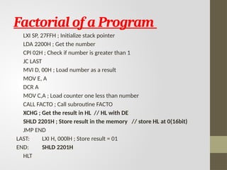
Factorial of aProgram
LXI SP, 27FFH ; Initialize stack pointer
LDA 2200H ; Get the number
CPI 02H ; Check if number is greater than 1
JC LAST
MVI D, 00H ; Load number as a result
MOV E, A
DCR A
MOV C,A ; Load counter one less than number
CALL FACTO ; Call subroutine FACTO
XCHG ; Get the result in HL // HL with DE
SHLD 2201H ; Store result in the memory // store HL at 0(16bit)
JMP END
LAST: LXI H, 000lH ; Store result = 01
END: SHLD 2201H
HLT
43.
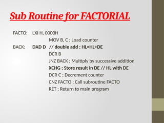
Sub Routine forFACTORIAL
FACTO: LXI H, 0000H
MOV B, C ; Load counter
BACK: DAD D // double add ; HL=HL+DE
DCR B
JNZ BACK ; Multiply by successive addition
XCHG ; Store result in DE // HL with DE
DCR C ; Decrement counter
CNZ FACTO ; Call subroutine FACTO
RET ; Return to main program
44.
8085 Simulator &Kit
• 8085 Simulator is available
• Course website
• 8085 Kit is available in HW Lab (CS422)
• First test the program on Simulator and then go for the HW
• Sometime Kit have Driver, IDE and Assembler