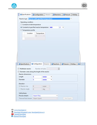
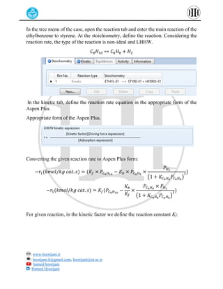
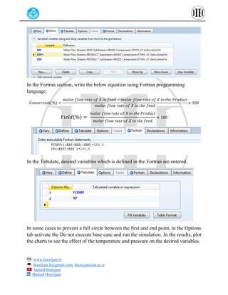
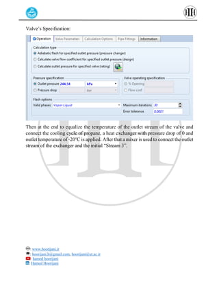
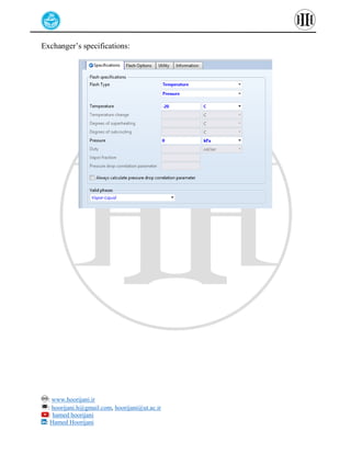
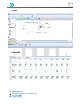
: www.hoorijani.ir
: hoorijani.h@gmail.com, hoorijani@ut.ac.ir
: hamed hoorijani
: Hamed Hoorijani
Tutorial Aspen Plus
1. LHHW reaction type
2. Reverse Propane cycle
Author: Hamed Hoorijani
: www.hoorijani.ir
: hoorijani.h@gmail.com, hoorijani@ut.ac.ir
: hamed hoorijani
: Hamed Hoorijani
Tutorial 1. Reaction rate for the conversion of the ethylbenzene to styrene is
given in the below form:
𝐶8𝐻10 ↔ 𝐶8𝐻8 + 𝐻2
−𝑟1(𝑘𝑚𝑜𝑙/𝑘𝑔 𝑐𝑎𝑡. 𝑠) = (𝐾𝑓 × 𝑃𝐶8𝐻10
−
𝐾𝑏 × 𝑃𝐶8𝐻8
× 𝑃𝐻2
(1 + 𝐾𝐶8𝐻8
𝑃𝐶8𝐻8
)
1)
−𝑟1(𝑘𝑚𝑜𝑙/𝑘𝑔 𝑐𝑎𝑡. 𝑠)
= (2.3496 × e
(−(
158600
𝑅𝑇
))
× 𝑃𝐶8𝐻10
− 3.7594 × 10⁻¹²
× 𝑒
−(
34339
𝑅𝑇
)
× 𝑃𝐶8𝐻8
×
𝑃𝐻2
(1 + 1.13 × 10⁻⁴𝑃𝐶8𝐻8
)
1)
Ethylbenzene also forms two more side reactions in the reactor which their reaction
rates are as below:
𝐶8𝐻10 → 𝐶6𝐻6 + 𝐶𝐻2𝐶𝐻2
−𝑟2(𝑘𝑚𝑜𝑙/𝑘𝑔 𝑐𝑎𝑡. 𝑠) = 1.37606 × 10⁻⁶
× 𝑒
−(
114200
𝑅𝑇
)
× 𝑃𝐶8𝐻10
𝐶8𝐻10 + 𝐻2 → 𝐶7𝐻8 + 𝐶𝐻4
−𝑟3(𝑘𝑚𝑜𝑙/𝑘𝑔 𝑐𝑎𝑡. 𝑠) = 47.4107 × 𝑒
−(
208000
𝑅𝑇
)
× 𝑃𝐶8𝐻10
Show the effect of the reactor’s temperature and pressure on conversion and reaction
yield in a plug reactor. Feed’s properties: 60kmole ethylbenzene, 600kmole
Hydrogen @ 600℃ - Pressure of 1.5 atm. Catalytic reactor with 28000kg catalysts
and bed porosity of 0.455.
Source: Exercise 7.2 of Kamal I.M. al-Malah, ASPEN PLUS chemical
engineering application, Wiley (Page 222)
: www.hoorijani.ir
: hoorijani.h@gmail.com, hoorijani@ut.ac.ir
: hamed hoorijani
: Hamed Hoorijani
Solution
Choose PENG-ROB as the appropriate thermodynamic package and obtain the pair
coefficients for the materials. In the flowsheet, define the Feed stream that enters the
RPlug reactor.
In the specifications tab of the reactor, choose reactor with specified temperature for
the reactor type and set it as 600℃. In the configuration tab of the reactor, choose
the single pipe with diameter and length of 5m.
: www.hoorijani.ir
: hoorijani.h@gmail.com, hoorijani@ut.ac.ir
: hamed hoorijani
: Hamed Hoorijani
: www.hoorijani.ir
: hoorijani.h@gmail.com, hoorijani@ut.ac.ir
: hamed hoorijani
: Hamed Hoorijani
In the tree menu of the case, open the reaction tab and enter the main reaction of the
ethylbenzene to styrene. At the stoichiometry, define the reaction. Considering the
reaction rate, the type of the reaction is non-ideal and LHHW.
𝐶8𝐻10 ↔ 𝐶8𝐻8 + 𝐻2
In the kinetic tab, define the reaction rate equation in the appropriate form of the
Aspen Plus.
Appropriate form of the Aspen Plus.
Converting the given reaction rate to Aspen Plus form:
−𝑟1(𝑘𝑚𝑜𝑙/𝑘𝑔 𝑐𝑎𝑡. 𝑠) = (𝐾𝑓 × 𝑃𝐶8𝐻10
− 𝐾𝑏 × 𝑃𝐶8𝐻8
×
𝑃𝐻2
(1 + 𝐾𝐶8𝐻8
𝑃𝐶8𝐻8
)
1)
−𝑟1(𝑘𝑚𝑜𝑙/𝑘𝑔 𝑐𝑎𝑡. 𝑠) = 𝐾𝑓(𝑃𝐶8𝐻10
−
𝐾𝑏
𝐾𝑓
×
𝑃𝐶8𝐻8
× 𝑃𝐻2
(1 + 𝐾𝐶8𝐻8
𝑃𝐶8𝐻8
)
1)
For given reaction, in the kinetic factor we define the reaction constant Kf:
: www.hoorijani.ir
: hoorijani.h@gmail.com, hoorijani@ut.ac.ir
: hamed hoorijani
: Hamed Hoorijani
In the Driving Force and adsorption, transform each expression in the below form
and define them in the proper fields. In the basis, choose Partial pressure for the basis
of the reaction rates.
ln 𝑘 = 𝐴 +
𝐵
𝑇
+ 𝐶𝑇 + ln(𝑇)
For the coefficients of the Term 2, use the bellow’s expression and gain the
coefficients.
ln
𝐾𝑏
𝐾𝑓
= 𝐴 +
𝐵
𝑇
+ 𝐶𝑇 + ln(𝑇)
: www.hoorijani.ir
: hoorijani.h@gmail.com, hoorijani@ut.ac.ir
: hamed hoorijani
: Hamed Hoorijani
Adsorption Section:
: www.hoorijani.ir
: hoorijani.h@gmail.com, hoorijani@ut.ac.ir
: hamed hoorijani
: Hamed Hoorijani
In the Reaction section, define a new reaction as R-2 typed POWERLAW to enter
the side reactions. In the stoichiometry section, define the stoichiometry of the side
reactions.
In the kinetic, define the reaction rate suitable to Powerlaw reaction type.
Considering the catalytic reaction, in the Rate basis choose the “Cat (wt)” and
reacting phase as “Vapor”.
: www.hoorijani.ir
: hoorijani.h@gmail.com, hoorijani@ut.ac.ir
: hamed hoorijani
: Hamed Hoorijani
In the reactions of the RPlug reactor, add the two defined reaction set. In the Pressure
tab of the reactor, enter the inlet stream pressure as 1.5atm and pressure drop in the
reactor as 0.
: www.hoorijani.ir
: hoorijani.h@gmail.com, hoorijani@ut.ac.ir
: hamed hoorijani
: Hamed Hoorijani
In the Catalysts of the reactor, activate “Catalyst present in reactor” and enter the
specifications of the catalysts according to the given data.
After defining the catalyst in the reactor, run the simulation and observe the results.
: www.hoorijani.ir
: hoorijani.h@gmail.com, hoorijani@ut.ac.ir
: hamed hoorijani
: Hamed Hoorijani
To study the effect of the reactor’s temperature and pressure on the reaction
conversion and yield, in the tree chart of the case “Model Analysis Tools/Sensivity”,
define a new Sensivity case. In the Vary choose the reactor’s temperature between
500-700℃ and reactor’s pressure between 1-5 atm.
: www.hoorijani.ir
: hoorijani.h@gmail.com, hoorijani@ut.ac.ir
: hamed hoorijani
: Hamed Hoorijani
To define the reation conversion and yield, molar flow of the ethylbenzene in the
feed stream is defined in the Sensivity/Define.
: www.hoorijani.ir
: hoorijani.h@gmail.com, hoorijani@ut.ac.ir
: hamed hoorijani
: Hamed Hoorijani
In the Fortran section, write the below equation using Fortran programming
language.
𝐶𝑜𝑛𝑣𝑒𝑟𝑠𝑖𝑜𝑛(%) =
𝑚𝑜𝑙𝑎𝑟 𝑓𝑙𝑜𝑤 𝑟𝑎𝑡𝑒 𝑜𝑓 𝑋 𝑖𝑛 𝑓𝑒𝑒𝑑 − 𝑚𝑜𝑙𝑎𝑟 𝑓𝑙𝑜𝑤 𝑟𝑎𝑡𝑒 𝑜𝑓 𝑋 𝑖𝑛 𝑡ℎ𝑒 𝑃𝑟𝑜𝑑𝑢𝑐𝑡
𝑚𝑜𝑙𝑎𝑟 𝑓𝑙𝑜𝑤 𝑟𝑎𝑡𝑒 𝑜𝑓 𝑋 𝑖𝑛 𝑡ℎ𝑒 𝑓𝑒𝑒𝑑
× 100
𝑌𝑖𝑒𝑙𝑑(%) =
𝑚𝑜𝑙𝑎𝑟 𝑓𝑙𝑜𝑤 𝑟𝑎𝑡𝑒 𝑜𝑓 𝑋 𝑖𝑛 𝑡ℎ𝑒 𝑃𝑟𝑜𝑑𝑢𝑐𝑡
𝑚𝑜𝑙𝑎𝑟 𝑓𝑙𝑜𝑤 𝑟𝑎𝑡𝑒 𝑜𝑓 𝑋 𝑖𝑛 𝑡ℎ𝑒 𝑓𝑒𝑒𝑑
× 100
In the Tabulate, desired variables which is defined in the Fortran are entered.
In some cases to prevent a full circle between the first and end point, in the Options
tab activate the Do not execute base case and run the simulation. In the results, plot
the charts to see the effect of the temperature and pressure on the desired variables.
: www.hoorijani.ir
: hoorijani.h@gmail.com, hoorijani@ut.ac.ir
: hamed hoorijani
: Hamed Hoorijani
: www.hoorijani.ir
: hoorijani.h@gmail.com, hoorijani@ut.ac.ir
: hamed hoorijani
: Hamed Hoorijani
Tutorial 2.
With considering the required modifications simulate the reverse propane cycle.
Propane cycle
: www.hoorijani.ir
: hoorijani.h@gmail.com, hoorijani@ut.ac.ir
: hamed hoorijani
: Hamed Hoorijani
Solution
After defining propane in the Components section, choose Peng-Rob as the proper
thermodynamic package. In the simulation section, first define the “Stream 3”
according to the given stream’s specs. Consider a thoeretical molar flow for the
stream to have the rest of the streams properties and afterward we determine the
proper value for the molar flow of this stream.
To restore the pressure drop in the chiller of the main propane cycle, a compressor
with 7kPa increasing pressure can be considered in the proceess path as the vapor
fraction of the stream equal to 1. Also to reverse the effec of the temperature’s
change a cooler can be used.
: www.hoorijani.ir
: hoorijani.h@gmail.com, hoorijani@ut.ac.ir
: hamed hoorijani
: Hamed Hoorijani
Cooler specs:
Cooler’s outlet is the “Stream 2” and to reverse the pressure drop of the J-T valve, a
heater is used to have a vapor fraction of 1 for the stream. The outlet stream of the
heater is then entered into a compressor to increase the temperature.
: www.hoorijani.ir
: hoorijani.h@gmail.com, hoorijani@ut.ac.ir
: hamed hoorijani
: Hamed Hoorijani
Specifications VF1:
So to increase the pressure a compressor is define and using another exchanger, set
the outlet streams vapor fraction as 0 and consider pressure drop as 0.
Simulation Hint:
To obtain the value for the pressure increase in compressor, you can gain the “Stream
1” pressure using defining it and process it through a mixer to have the Aspen Plus
calculated the properties. Another approach is to calculate the pressure drop between
the “Stream 1” and “S1” and enter its value as the increasing pressure value for the
compressor.
: www.hoorijani.ir
: hoorijani.h@gmail.com, hoorijani@ut.ac.ir
: hamed hoorijani
: Hamed Hoorijani
Compressor’s Specifications:
Specifications VF0:
: www.hoorijani.ir
: hoorijani.h@gmail.com, hoorijani@ut.ac.ir
: hamed hoorijani
: Hamed Hoorijani
Flowsheet:
Now to eliminate the two heat exchangers which there aren’t in the main flowsheet
originally (VF0 and VF1), a mixer to mix the energy streams of these two exchangers
is defined. With considering a “Design Spec” the summation of these two energy
streams aims to be zero with changing the molar flow of the “Stream 3”. In another
word, using this way these two equipment’s effect neutralized in the process and the
reverse process achieves.
Flowsheet:
Parameters Design Spec:
: www.hoorijani.ir
: hoorijani.h@gmail.com, hoorijani@ut.ac.ir
: hamed hoorijani
: Hamed Hoorijani
: www.hoorijani.ir
: hoorijani.h@gmail.com, hoorijani@ut.ac.ir
: hamed hoorijani
: Hamed Hoorijani
Design Spec results:
To gain the “Stream 4” properties, first consider a pump (Cause the vapor fraction
of the “Stream 1” equal 0) and then a heat exchanger (heater).
: www.hoorijani.ir
: hoorijani.h@gmail.com, hoorijani@ut.ac.ir
: hamed hoorijani
: Hamed Hoorijani
Pump’s specifications:
: www.hoorijani.ir
: hoorijani.h@gmail.com, hoorijani@ut.ac.ir
: hamed hoorijani
: Hamed Hoorijani
Exchanger’s specifications:
To reverse a compressor’s effect, a valve can be installed in the process path and
with having the pressure of the “Stream 3” you can enter the outlet pressure of the
valve.
: www.hoorijani.ir
: hoorijani.h@gmail.com, hoorijani@ut.ac.ir
: hamed hoorijani
: Hamed Hoorijani
Valve’s Specification:
Then at the end to equalize the temperature of the outlet stream of the valve and
connect the cooling cycle of propane, a heat exchanger with pressure drop of 0 and
outlet temperature of -20℃ is applied. After that a mixer is used to connect the outlet
stream of the exchanger and the initial “Stream 3”.
: www.hoorijani.ir
: hoorijani.h@gmail.com, hoorijani@ut.ac.ir
: hamed hoorijani
: Hamed Hoorijani
Exchanger’s specifications:
: www.hoorijani.ir
: hoorijani.h@gmail.com, hoorijani@ut.ac.ir
: hamed hoorijani
: Hamed Hoorijani
Flowsheet:
Stream results:

Aspen Plus Tutorial - LHHW - reverse propane cycle

  • 1.
    : www.hoorijani.ir : hoorijani.h@gmail.com,hoorijani@ut.ac.ir : hamed hoorijani : Hamed Hoorijani Tutorial Aspen Plus 1. LHHW reaction type 2. Reverse Propane cycle Author: Hamed Hoorijani
  • 2.
    : www.hoorijani.ir : hoorijani.h@gmail.com,hoorijani@ut.ac.ir : hamed hoorijani : Hamed Hoorijani Tutorial 1. Reaction rate for the conversion of the ethylbenzene to styrene is given in the below form: 𝐶8𝐻10 ↔ 𝐶8𝐻8 + 𝐻2 −𝑟1(𝑘𝑚𝑜𝑙/𝑘𝑔 𝑐𝑎𝑡. 𝑠) = (𝐾𝑓 × 𝑃𝐶8𝐻10 − 𝐾𝑏 × 𝑃𝐶8𝐻8 × 𝑃𝐻2 (1 + 𝐾𝐶8𝐻8 𝑃𝐶8𝐻8 ) 1) −𝑟1(𝑘𝑚𝑜𝑙/𝑘𝑔 𝑐𝑎𝑡. 𝑠) = (2.3496 × e (−( 158600 𝑅𝑇 )) × 𝑃𝐶8𝐻10 − 3.7594 × 10⁻¹² × 𝑒 −( 34339 𝑅𝑇 ) × 𝑃𝐶8𝐻8 × 𝑃𝐻2 (1 + 1.13 × 10⁻⁴𝑃𝐶8𝐻8 ) 1) Ethylbenzene also forms two more side reactions in the reactor which their reaction rates are as below: 𝐶8𝐻10 → 𝐶6𝐻6 + 𝐶𝐻2𝐶𝐻2 −𝑟2(𝑘𝑚𝑜𝑙/𝑘𝑔 𝑐𝑎𝑡. 𝑠) = 1.37606 × 10⁻⁶ × 𝑒 −( 114200 𝑅𝑇 ) × 𝑃𝐶8𝐻10 𝐶8𝐻10 + 𝐻2 → 𝐶7𝐻8 + 𝐶𝐻4 −𝑟3(𝑘𝑚𝑜𝑙/𝑘𝑔 𝑐𝑎𝑡. 𝑠) = 47.4107 × 𝑒 −( 208000 𝑅𝑇 ) × 𝑃𝐶8𝐻10 Show the effect of the reactor’s temperature and pressure on conversion and reaction yield in a plug reactor. Feed’s properties: 60kmole ethylbenzene, 600kmole Hydrogen @ 600℃ - Pressure of 1.5 atm. Catalytic reactor with 28000kg catalysts and bed porosity of 0.455. Source: Exercise 7.2 of Kamal I.M. al-Malah, ASPEN PLUS chemical engineering application, Wiley (Page 222)
  • 3.
    : www.hoorijani.ir : hoorijani.h@gmail.com,hoorijani@ut.ac.ir : hamed hoorijani : Hamed Hoorijani Solution Choose PENG-ROB as the appropriate thermodynamic package and obtain the pair coefficients for the materials. In the flowsheet, define the Feed stream that enters the RPlug reactor. In the specifications tab of the reactor, choose reactor with specified temperature for the reactor type and set it as 600℃. In the configuration tab of the reactor, choose the single pipe with diameter and length of 5m.
  • 4.
    : www.hoorijani.ir : hoorijani.h@gmail.com,hoorijani@ut.ac.ir : hamed hoorijani : Hamed Hoorijani
  • 5.
    : www.hoorijani.ir : hoorijani.h@gmail.com,hoorijani@ut.ac.ir : hamed hoorijani : Hamed Hoorijani In the tree menu of the case, open the reaction tab and enter the main reaction of the ethylbenzene to styrene. At the stoichiometry, define the reaction. Considering the reaction rate, the type of the reaction is non-ideal and LHHW. 𝐶8𝐻10 ↔ 𝐶8𝐻8 + 𝐻2 In the kinetic tab, define the reaction rate equation in the appropriate form of the Aspen Plus. Appropriate form of the Aspen Plus. Converting the given reaction rate to Aspen Plus form: −𝑟1(𝑘𝑚𝑜𝑙/𝑘𝑔 𝑐𝑎𝑡. 𝑠) = (𝐾𝑓 × 𝑃𝐶8𝐻10 − 𝐾𝑏 × 𝑃𝐶8𝐻8 × 𝑃𝐻2 (1 + 𝐾𝐶8𝐻8 𝑃𝐶8𝐻8 ) 1) −𝑟1(𝑘𝑚𝑜𝑙/𝑘𝑔 𝑐𝑎𝑡. 𝑠) = 𝐾𝑓(𝑃𝐶8𝐻10 − 𝐾𝑏 𝐾𝑓 × 𝑃𝐶8𝐻8 × 𝑃𝐻2 (1 + 𝐾𝐶8𝐻8 𝑃𝐶8𝐻8 ) 1) For given reaction, in the kinetic factor we define the reaction constant Kf:
  • 6.
    : www.hoorijani.ir : hoorijani.h@gmail.com,hoorijani@ut.ac.ir : hamed hoorijani : Hamed Hoorijani In the Driving Force and adsorption, transform each expression in the below form and define them in the proper fields. In the basis, choose Partial pressure for the basis of the reaction rates. ln 𝑘 = 𝐴 + 𝐵 𝑇 + 𝐶𝑇 + ln(𝑇) For the coefficients of the Term 2, use the bellow’s expression and gain the coefficients. ln 𝐾𝑏 𝐾𝑓 = 𝐴 + 𝐵 𝑇 + 𝐶𝑇 + ln(𝑇)
  • 7.
    : www.hoorijani.ir : hoorijani.h@gmail.com,hoorijani@ut.ac.ir : hamed hoorijani : Hamed Hoorijani Adsorption Section:
  • 8.
    : www.hoorijani.ir : hoorijani.h@gmail.com,hoorijani@ut.ac.ir : hamed hoorijani : Hamed Hoorijani In the Reaction section, define a new reaction as R-2 typed POWERLAW to enter the side reactions. In the stoichiometry section, define the stoichiometry of the side reactions. In the kinetic, define the reaction rate suitable to Powerlaw reaction type. Considering the catalytic reaction, in the Rate basis choose the “Cat (wt)” and reacting phase as “Vapor”.
  • 9.
    : www.hoorijani.ir : hoorijani.h@gmail.com,hoorijani@ut.ac.ir : hamed hoorijani : Hamed Hoorijani In the reactions of the RPlug reactor, add the two defined reaction set. In the Pressure tab of the reactor, enter the inlet stream pressure as 1.5atm and pressure drop in the reactor as 0.
  • 10.
    : www.hoorijani.ir : hoorijani.h@gmail.com,hoorijani@ut.ac.ir : hamed hoorijani : Hamed Hoorijani In the Catalysts of the reactor, activate “Catalyst present in reactor” and enter the specifications of the catalysts according to the given data. After defining the catalyst in the reactor, run the simulation and observe the results.
  • 11.
    : www.hoorijani.ir : hoorijani.h@gmail.com,hoorijani@ut.ac.ir : hamed hoorijani : Hamed Hoorijani To study the effect of the reactor’s temperature and pressure on the reaction conversion and yield, in the tree chart of the case “Model Analysis Tools/Sensivity”, define a new Sensivity case. In the Vary choose the reactor’s temperature between 500-700℃ and reactor’s pressure between 1-5 atm.
  • 12.
    : www.hoorijani.ir : hoorijani.h@gmail.com,hoorijani@ut.ac.ir : hamed hoorijani : Hamed Hoorijani To define the reation conversion and yield, molar flow of the ethylbenzene in the feed stream is defined in the Sensivity/Define.
  • 13.
    : www.hoorijani.ir : hoorijani.h@gmail.com,hoorijani@ut.ac.ir : hamed hoorijani : Hamed Hoorijani In the Fortran section, write the below equation using Fortran programming language. 𝐶𝑜𝑛𝑣𝑒𝑟𝑠𝑖𝑜𝑛(%) = 𝑚𝑜𝑙𝑎𝑟 𝑓𝑙𝑜𝑤 𝑟𝑎𝑡𝑒 𝑜𝑓 𝑋 𝑖𝑛 𝑓𝑒𝑒𝑑 − 𝑚𝑜𝑙𝑎𝑟 𝑓𝑙𝑜𝑤 𝑟𝑎𝑡𝑒 𝑜𝑓 𝑋 𝑖𝑛 𝑡ℎ𝑒 𝑃𝑟𝑜𝑑𝑢𝑐𝑡 𝑚𝑜𝑙𝑎𝑟 𝑓𝑙𝑜𝑤 𝑟𝑎𝑡𝑒 𝑜𝑓 𝑋 𝑖𝑛 𝑡ℎ𝑒 𝑓𝑒𝑒𝑑 × 100 𝑌𝑖𝑒𝑙𝑑(%) = 𝑚𝑜𝑙𝑎𝑟 𝑓𝑙𝑜𝑤 𝑟𝑎𝑡𝑒 𝑜𝑓 𝑋 𝑖𝑛 𝑡ℎ𝑒 𝑃𝑟𝑜𝑑𝑢𝑐𝑡 𝑚𝑜𝑙𝑎𝑟 𝑓𝑙𝑜𝑤 𝑟𝑎𝑡𝑒 𝑜𝑓 𝑋 𝑖𝑛 𝑡ℎ𝑒 𝑓𝑒𝑒𝑑 × 100 In the Tabulate, desired variables which is defined in the Fortran are entered. In some cases to prevent a full circle between the first and end point, in the Options tab activate the Do not execute base case and run the simulation. In the results, plot the charts to see the effect of the temperature and pressure on the desired variables.
  • 14.
    : www.hoorijani.ir : hoorijani.h@gmail.com,hoorijani@ut.ac.ir : hamed hoorijani : Hamed Hoorijani
  • 15.
    : www.hoorijani.ir : hoorijani.h@gmail.com,hoorijani@ut.ac.ir : hamed hoorijani : Hamed Hoorijani Tutorial 2. With considering the required modifications simulate the reverse propane cycle. Propane cycle
  • 16.
    : www.hoorijani.ir : hoorijani.h@gmail.com,hoorijani@ut.ac.ir : hamed hoorijani : Hamed Hoorijani Solution After defining propane in the Components section, choose Peng-Rob as the proper thermodynamic package. In the simulation section, first define the “Stream 3” according to the given stream’s specs. Consider a thoeretical molar flow for the stream to have the rest of the streams properties and afterward we determine the proper value for the molar flow of this stream. To restore the pressure drop in the chiller of the main propane cycle, a compressor with 7kPa increasing pressure can be considered in the proceess path as the vapor fraction of the stream equal to 1. Also to reverse the effec of the temperature’s change a cooler can be used.
  • 17.
    : www.hoorijani.ir : hoorijani.h@gmail.com,hoorijani@ut.ac.ir : hamed hoorijani : Hamed Hoorijani Cooler specs: Cooler’s outlet is the “Stream 2” and to reverse the pressure drop of the J-T valve, a heater is used to have a vapor fraction of 1 for the stream. The outlet stream of the heater is then entered into a compressor to increase the temperature.
  • 18.
    : www.hoorijani.ir : hoorijani.h@gmail.com,hoorijani@ut.ac.ir : hamed hoorijani : Hamed Hoorijani Specifications VF1: So to increase the pressure a compressor is define and using another exchanger, set the outlet streams vapor fraction as 0 and consider pressure drop as 0. Simulation Hint: To obtain the value for the pressure increase in compressor, you can gain the “Stream 1” pressure using defining it and process it through a mixer to have the Aspen Plus calculated the properties. Another approach is to calculate the pressure drop between the “Stream 1” and “S1” and enter its value as the increasing pressure value for the compressor.
  • 19.
    : www.hoorijani.ir : hoorijani.h@gmail.com,hoorijani@ut.ac.ir : hamed hoorijani : Hamed Hoorijani Compressor’s Specifications: Specifications VF0:
  • 20.
    : www.hoorijani.ir : hoorijani.h@gmail.com,hoorijani@ut.ac.ir : hamed hoorijani : Hamed Hoorijani Flowsheet: Now to eliminate the two heat exchangers which there aren’t in the main flowsheet originally (VF0 and VF1), a mixer to mix the energy streams of these two exchangers is defined. With considering a “Design Spec” the summation of these two energy streams aims to be zero with changing the molar flow of the “Stream 3”. In another word, using this way these two equipment’s effect neutralized in the process and the reverse process achieves. Flowsheet: Parameters Design Spec:
  • 21.
    : www.hoorijani.ir : hoorijani.h@gmail.com,hoorijani@ut.ac.ir : hamed hoorijani : Hamed Hoorijani
  • 22.
    : www.hoorijani.ir : hoorijani.h@gmail.com,hoorijani@ut.ac.ir : hamed hoorijani : Hamed Hoorijani Design Spec results: To gain the “Stream 4” properties, first consider a pump (Cause the vapor fraction of the “Stream 1” equal 0) and then a heat exchanger (heater).
  • 23.
    : www.hoorijani.ir : hoorijani.h@gmail.com,hoorijani@ut.ac.ir : hamed hoorijani : Hamed Hoorijani Pump’s specifications:
  • 24.
    : www.hoorijani.ir : hoorijani.h@gmail.com,hoorijani@ut.ac.ir : hamed hoorijani : Hamed Hoorijani Exchanger’s specifications: To reverse a compressor’s effect, a valve can be installed in the process path and with having the pressure of the “Stream 3” you can enter the outlet pressure of the valve.
  • 25.
    : www.hoorijani.ir : hoorijani.h@gmail.com,hoorijani@ut.ac.ir : hamed hoorijani : Hamed Hoorijani Valve’s Specification: Then at the end to equalize the temperature of the outlet stream of the valve and connect the cooling cycle of propane, a heat exchanger with pressure drop of 0 and outlet temperature of -20℃ is applied. After that a mixer is used to connect the outlet stream of the exchanger and the initial “Stream 3”.
  • 26.
    : www.hoorijani.ir : hoorijani.h@gmail.com,hoorijani@ut.ac.ir : hamed hoorijani : Hamed Hoorijani Exchanger’s specifications:
  • 27.
    : www.hoorijani.ir : hoorijani.h@gmail.com,hoorijani@ut.ac.ir : hamed hoorijani : Hamed Hoorijani Flowsheet: Stream results: