Download to read offline
![International Research Journal of Engineering and Technology (IRJET) e-ISSN: 2395-0056
Volume: 09 Issue: 10 | Oct 2022 www.irjet.net p-ISSN: 2395-0072
© 2022, IRJET | Impact Factor value: 7.529 | ISO 9001:2008 Certified Journal | Page 759
Area Efficient 9/7 Wavelet Coefficient based 2-D DWT using Modified
CSLA Technique
Megha Chaturvedi1, Prof. Gurpreet Singh2
1 Research Scholar, Trinity Institute of Technology & Research, Bhopal, India
2 Professor Electronics’ & Communication Dept., Trinity Institute of Technology & Research, Bhopal, India
---------------------------------------------------------------------***---------------------------------------------------------------------
Abstract - The DWT is expressed in a generalized form
know as discrete wavelet transform which analyzes both the
low and high sub bands at every levelof breakdownwithequal
priority. A pragmatic approach to signal processing is
provided by the DWT mathematical technique. It is frequently
utilized in many signal and image processing applications
because of its many beneficial qualities, suchasadaptivetime-
frequency window, decreased aliasing distortion, andefficient
computing complexity. In order to compress images and
videos, 2-D DWT is frequently utilized. But in some DWT
architectures, flipping approach adds considerable design
complexity. In order to give multiplier-less implementation
and ensure that our suggested work would function for every
bit, we have included the BK adder and MDA approach. In
comparison to the previous approach, the suggestedMDA and
MCSLA-based 2-D DWT algorithm exhibits goodperformance.
The suggested architecture for DWT implementation
minimizes the maximum combinational path delay while also
reducing chip size and computation time.
Key Words: VHDL Simulation, 2-D DWT, MDA, Low-pass
Sub-band (LPSB), High-pass Sub-band (HPSB)
1. INTRODUCTION
Engineering professionals choose digital signal processing
methods based on the characteristics of the signal being
studied. The two main methods utilizedcommonlyforsignal
analysis are frequency-based and time-frequency-based
methods. A stationarysignal isanalyzedusingthefrequency-
based method (FBT), while non-stationary signals are
typically analyzed using time-frequency techniques (TFT),
such as the short time Fourier transform (STFT), wavelet
transform, etc. Although no information is obtained in the
time domain, the FBT offers energy information of the
function in the frequency domain. A musical note or a
vehicle's noises are examples of non-stationary signalsfrom
which the TFT captures the transient properties and
represents them in a time-frequency map forsignal analysis.
[1, 2].
Over the years wavelet transform has emerged as a
predominant tool for time-frequency decomposition of a
signal. Wavelet is designed especially to study the non-
stationary data, and due to its generality and accurate
results, it has become useful in a number of areas. For a non-
stationary signal, the frequency content at a particular point
in time is different from the frequency content at another
point, e.g., a sudden transient [3]. The Fourier transform is
not able to specify accurately at what point in time the
transient occurs becausetheFourierbasesaresinusoidsthat
are infinite in extent and can give information only based on
the entire duration of the signal.Hence,theFourierbases are
not able to localize the important events of the signal.Onthe
contrary, wavelet has bases of finite duration, and this
property enables it to identify and locate in time the
important events in the signal which can be used to
differentiate one signal from the other efficiently [4, 5].
Wavelet analysis allows researchers to isolate and
manipulate the specific type of in formation hidden in the
data, similar to the human ear picking the sound of the flute
in a symphony. A diverse variety of wavelets can be used to
analyze a signal, the type of wavelet to be used depends on
the application. Wavelet is found in different branches from
the signal analysis to the problems in engineering, physics,
and mathematics. In the signal processing application,
wavelet is mainly used in analyzing the non-stationary
signals to provide the time-frequency information of an
important transient [6]. In the bio-medical engineering,
earth or ocean engineering the transient always carry a
significant amount of information for therespectivedomain.
The wavelet transform is found to be particularly useful for
analyzing the signals that are considered to beaperiodicand
noisy. The ability to analyze a signal distinctly both in time
and frequency simultaneously has set wavelet transform
apart from the STFT. Hence, wavelet transform is used to
investigate a variety of physical phenomena such as climate
change analysis, heart monitoring, seismicsignal de-noising,
astronomical image de-noising, video and image
compression [7, 8].
2. DISCRETE WAVELET TRANSFORM
The history of DWT goes back to the year 1976 when a
technique was invented by Croiser, Galand, and Esteban to
decompose the discrete time signals. In the same year,
Flanagan, Crochiere, and Weberconducteda similaranalysis
on the voice signal. The technique was named as sub-band
coding. Burt developeda methodknownaspyramidal coding
in 1983 that is comparable to sub-band coding, sometimes
referred to as multi-resolution analysis. The pyramidal
coding system still had redundant information thatmightbe
removed. By removing the redundant code from the](https://image.slidesharecdn.com/irjet-v9i10120-221110080035-24e3239c/85/Area-Efficient-9-7-Wavelet-Coefficient-based-2-D-DWT-using-Modified-CSLA-Technique-1-320.jpg)
![International Research Journal of Engineering and Technology (IRJET) e-ISSN: 2395-0056
Volume: 09 Issue: 10 | Oct 2022 www.irjet.net p-ISSN: 2395-0072
© 2022, IRJET | Impact Factor value: 7.529 | ISO 9001:2008 Certified Journal | Page 760
pyramidal coding in 1989, Vetterli and Le Gall improved the
sub-band coding [9]. The DWT, when compared with the
CWT is considerably easier to develop and implement.
Although the CWT can be discretized and computed for
DWT, the accurate discrete transform is not obtained. The
information provided by this sampled version of the CWT is
highly redundant. On the other hand, analyzing this
redundant information takes a lot of time and energy. The
DWT, on the other hand, speeds up processing while still
extracting enough usable data from the signal for analysis
and synthesis. The DWT decomposes the input spectrum
into two sub-bands, namely the high-pass sub band and the
low-pass sub-band. A low-pass filter is used to filter the
input signal to produce a low-pass sub-band, while a high-
pass filter is used to produce a high-pass sub-band [10]. A
finite impulse response (FIR) filter with a short length is
used to create the low-pass and high-pass filters.Thispair of
low-pass and high-pass filter form a quadraturemirrorfilter
(QMF) for the perfect signal reconstruction. The
computation of the DWT using low pass andhigh-passfilters
is performed either by the convolution scheme or lifting
scheme [11].
Fig -1: Two Level Diagram of Discrete Wavelet Transform
3. PROPOSED ARCHITECTURE
Particular focus is placed on system performanceandcostin
digital systems. Effectiveperformancetypicallycomeswitha
larger price cost. However, with a moderate increase in the
hardware, better performance canbeobtained.Inthecourse
of a computation, addition and multiplication are the
fundamental operations that are performed frequently. The
speed with which these operations are performed has a
great impact on the overall performance of the digital
system. Since the beginning of the digital computers, many
fast algorithms for the basicarithmetic operations havebeen
developed and implemented [12, 13].
There has been continuous research and development
towards the newer algorithms. The main reason for the
emerging algorithms is the rapid change in the technology
used to implement these arithmetic operations. Besides the
dependence on the technology used to implement the
algorithm, it is the unique feature of the algorithm that
affects the performance of the arithmetic operator [14].
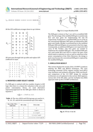
In this stream graph, the double information is connected to
the serial in serial out register. In the DWT design, all whole
numbers are related to the twofold frame. The word length
of two pieces of information, in this case 3 down to 0, means
that the range of the information is from 0 to 15.
Fig -2: Block Diagram of 9/7 Wavelet Coefficient based
Discrete Wavelet Transform
If takes the LPS coefficients h0, h1, h2, h3, and h4 multiply by
u1, u2, u3, u4 and u5 then multiplier-less 1-D DWT LPS output
is
5
4
3
2
1
4
3
2
1
0
u
u
u
u
u
h
h
h
h
h
YLPS
Where,
)
8
(
)
(
1
n
X
n
X
u
)
7
(
)
1
(
2
n
X
n
X
u
)
6
(
)
2
(
3
n
X
n
X
u
)
5
(
)
3
(
4
n
X
n
X
u
)
4
(
5
n
X
u
5
4
3
2
1
3
2
10
34
77
u
u
u
u
u
YLPS
So,](https://image.slidesharecdn.com/irjet-v9i10120-221110080035-24e3239c/85/Area-Efficient-9-7-Wavelet-Coefficient-based-2-D-DWT-using-Modified-CSLA-Technique-2-320.jpg)
![International Research Journal of Engineering and Technology (IRJET) e-ISSN: 2395-0056
Volume: 09 Issue: 10 | Oct 2022 www.irjet.net p-ISSN: 2395-0072
© 2022, IRJET | Impact Factor value: 7.529 | ISO 9001:2008 Certified Journal | Page 763
5. CONCLUSION
For this MDA technique is used which provides approach for
multiplier less implementation. It contains adder, shift
registers and free of multiplier.
Finally we have designed the 1-D and 2-D DWT using MCSLA
and MDA technique which provide better efficiency and
shows better results than the previous design.
DWT has been an important technique of multimedia
applications. This is not only the key algorithm of signal
processing, but has also led to revolutions inimageandvideo
coding algorithms. There are many DWT architectures of
flipping type, folded type andpipeline architecture forsignal
transform. Each structure has its own advantages and
disadvantages. However, an efficient architecture design of
DWT in JPEG 2000 is an important area of research to
explore.
REFERENCES
[1] Jhilam Jana, Sayan Tripathi, Ritesh Sur Chowdhury,
Akash Bhattacharya and Jaydeb Bhaumik, “An Area
Efficient VLSI Architecture for 1-D and 2-D Discrete
WaveletTransform(DWT)andInverseDiscrete Wavelet
Transform (IDWT)”, Devices for IntegratedCircuit,IEEE
2021.
[2] Zhang, W., Wu, C., Zhang, P. and Liu, Y., “An Internal
Folded Hardware-Efficient Architecture for Lifting-
Based Multi-Level 2-D 9/7 DWT”, 2019, Applied
Sciences, 9(21), p.4635.
[3] Samit Kumar Dubey, Arvind Kumar Kourav and Shilpi
Sharma, “High Speed 2-D Discrete Wavelet Transform
using Distributed Arithmetic and Kogge Stone Adder
Technique”, International Conference on
Communication and Signal Processing, April 6-8, 2017,
India.
[4] Rakesh Biswas, Siddarth Reddy Malreddy and Swapna
Banerjee, “A High Precision-Low Area Unified
Architecture for Lossy and Lossless 3D Multi-Level
Discrete Wavelet Transform”, IEEE Transactions on
Circuits and Systems for Video Technology, Vol. 45, No.
5, pp. 01-11, May 2017.
[5] Mamatha I, Shikha Tripathi and Sudarshan TSB,
“Pipelined Architecture for Filter Bank based1-DDWT”,
International Conference on Signal Processing and
Integrated Networks (SPIN), pp. 47-52, May 2016.
[6] Maurizio Martin and Guido Masera, Massimo Ruo Roch
and Gianluca Piccinini, “Result-Biased Distributed-
Arithmetic-BasedFilterArchitecturesforApproximately
Computing the DWT”, IEEE TransactionsonCircuitsand
Systems—I: Regular Papers, Vol. 62, No. 8, pp. 2103-
2113, August 2015.
[7] Basant Kumar Mohanty, Pramod Kumar Meher,
“Memory-Efficient High- Speed Convolution-based
Generic Structure for Multilevel 2-D DWT”, IEEE
transactions on Circuits, Systems for Video Technology,
Vol. 23, No. 2, pp. 353-363, February 2013.
[8] Basant K. Mohanty, Anurag Mahajan, Pramod K. Meher,
“Area- and Power-Efficient Architecture for High-
Throughput Implementation of Lifting 2-DDWT”, IEEE
Transactions on Circuits and Systems-II: Express Briefs,
Vol.59, No.7, pp. 434-438, July 2012.
[9] Chengjun Zhang, Chunyan Wang, M. Omair Ahmad, “A
Pipeline VLSI Architecture for High-Speed Computation
of the 1-D Discrete Wavelet Transform”, IEEE
transactions on Circuits and Systems-I; Regular Papers,
Vol.57, No.10, pp. 2729-2740, October 2010.
[10]Zhang, Chengjun, Chunyan Wang, and M. Omair Ahmad,
“A pipeline VLSI architecture for high-speed
computation of the 1-D discrete wavelet transform”,
IEEE Transactions on Circuits and Systems I: Regular
Papers, Vol.57, No. 10,pp: pp. 2729-2740, October2010.
[11]S. M. M. Rahman, M. O. Ahmad, and M. N. S. Swamy, “A
New Statistical Detector for DWT-Based AdditiveImage
Watermarking usingtheGauss-HermitExpansion,”IEEE
Transactions Image Processing, Vol. 18, No. 8, pp.
1782−1796, August 2009.
[12]P. K. Meher, B. K. Mohanty and J. C. Patra, “Hardware-
Efficient Systolic-Like Modula Design for Two-
Dimensional Discrete Wavelet Transform”, IEEE
Transactions on Circuits and Systems—Ii: Express
Briefs, Vol. 55, No. 2, pp. 1021-1029, February 2008.
[13]Chao Cheng, Keshab K. Parhi, “High-Speed VLSI
Implementation of 2-D Discrete Wavelet Transform”,
IEEE Transactions on Signal Processing,Vol.56,No.1, pp.
393-403, January 2008.
[14]C. C. Cheng, C.-T. Huang, C.-Y. Cheng, C.-Jr.Lian and L.-G.
Chen, “On-chip Memory Optimization scheme for VLSI
Implementation of Line-Based 2-D Discrete Wavelet
Transform,” IEEE TransactionsoncircuitandSystemfor
Video Technology, vol.17,no.7, pp. 814-822, July 2007.
[15]M. Martina, and G. Masera,“Multiplier less, folded 9/7-
5/3 wavelet VLSI Architecture, ”IEEE Transactions on
Circuits and System, Express Brief Vol. 54, No. 9, pp.
770- 774, September 2007.](https://image.slidesharecdn.com/irjet-v9i10120-221110080035-24e3239c/85/Area-Efficient-9-7-Wavelet-Coefficient-based-2-D-DWT-using-Modified-CSLA-Technique-5-320.jpg)

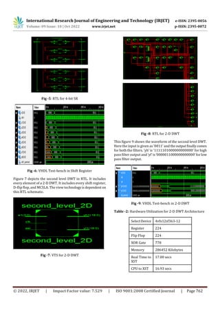
This document presents a proposed area efficient 9/7 wavelet coefficient based 2-D discrete wavelet transform (DWT) architecture using a modified carry select adder (MCSLA) technique. The proposed architecture aims to minimize circuit area and computation time compared to previous approaches. It uses a multiplier-less implementation with adders and shift registers. Simulation results show the proposed 2-D DWT design using the MCSLA and multiplier-delay addition approaches achieves better efficiency and performance than prior designs. The architecture provides an important technique for applications like image and video coding.