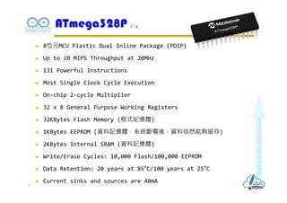
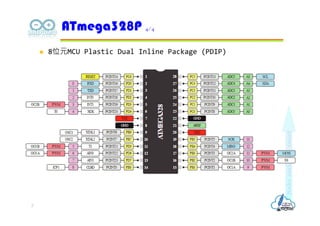
8位元MCU PlasticDual Inline Package (PDIP)
Up to 20 MIPS Throughput at 20MHz
131 Powerful Instructions
Most Single Clock Cycle Execution
On-chip 2-cycle Multiplier
32 x 8 General Purpose Working Registers
32KBytes Flash Memory (程式記憶體)
1KBytes EEPROM (資料記憶體,系統斷電後,資料依然能夠留存)
2KBytes Internal SRAM (資料記憶體)
Write/Erase Cycles: 10,000 Flash/100,000 EEPROM
Data Retention: 20 years at 85°C/100 years at 25°C
Current sinks and sources are 40mA
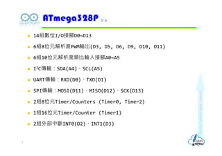
ATmega328P 2/4
5
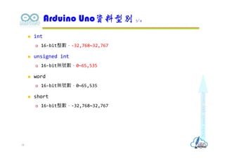
int
16-bit整數,-32,768~32,767
unsigned int
16-bit無號數,0~65,535
word
16-bit無號數,0~65,535
short
16-bit整數,-32,768~32,767
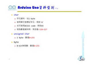
Arduino Uno資料型別 3/4
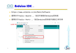
18