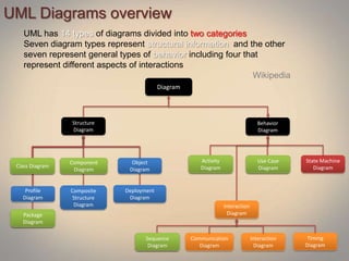
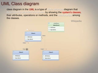
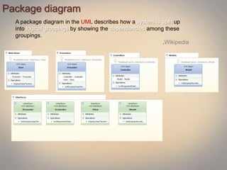
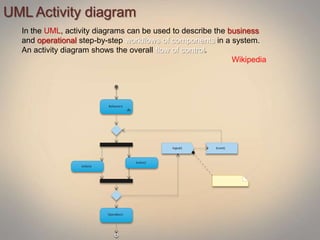
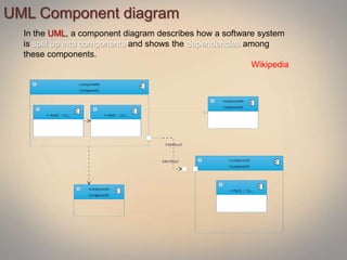
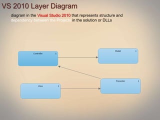
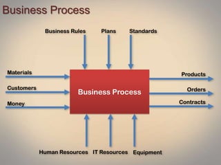
New England
CODE CAMP> Net Comm
www.boston
Modeling Architecture with
UMLVisual Studio 2010 Ultimate
About Me
Slava Kokaev – Business Intelligence
Consultant
at Magenic
Boston Microsoft BI USER GROUP
leader
email:
vkokaev@bostonbi.org
web:
www.bostonbi.org/blogs
Agenda
UML Diagrams
VS2010 Modeling Tools
Code and Model Generation
UML
Unified Modeling Language is a standardized
general purpose modeling language in the field of
object oriented software engineering
The standard is managed, and was created by, the Object
Management Group.
UML includes a set of graphic notation techniques to create visual
models of object-oriented software-intensive systems.
WIKIPEDIA
UML Diagrams overview
UML has 14 types of diagrams divided into two categories
Seven diagram types represent structural information and the other
seven represent general types of behavior including four that
represent different aspects of interactions
Wikipedia
Diagram
Structure
Diagram
Behavior
Diagram
Class Diagram
Component
Diagram
Object
Diagram
Profile
Diagram
Composite
Structure
Diagram
Deployment
Diagram
Package
Diagram
Activity
Diagram
Use Case
Diagram
State Machine
Diagram
Interaction
Diagram
Sequence
Diagram
Communication
Diagram
Interaction
Diagram
Timing
Diagram
Class Diagram
Component
Diagram
Package
Diagram
Activity
Diagram
Use Case
Diagram
Sequence
Diagram
UML Class diagram
class diagram in the UML is a type of static structure diagram that
describes the structure of a system by showing the system's classes,
their attributes, operations or methods, and the relationships among
the classes.
Wikipedia
Package diagram
A package diagram in the UML describes how a system is split up
into logical groupings by showing the dependencies among these
groupings.
.Wikipedia
UML Activity diagram
In the UML, activity diagrams can be used to describe the business
and operational step-by-step workflows of components in a system.
An activity diagram shows the overall flow of control.
Wikipedia
UML Component diagram
In the UML, a component diagram describes how a software system
is split up into components and shows the dependencies among
these components.
Wikipedia
UML Use case diagram
describes the functionality provided by a system in terms of actors,
their goals represented as use cases, and any dependencies among
those use cases.
Wikipedia
UML Sequence diagram
A sequence diagram in UML is a kind of interaction diagram that shows
how objects communicate with each other in terms of a sequence of
messages. Also indicates the lifespans of objects relative to those
messages.
Wikipedia
VS 2010 Layer Diagram
diagram in the Visual Studio 2010 that represents structure and
dependency between the Projects in the solution or DLLs
Enterprise Business Analysis System
Customers
Business
partners
Vendors, Suppliers, Channel partners
IT providers Financial service providers
Monitoring Systems Analysis Systems
Business Processes and Operations
Controlling Systems
Strategy and Planning
Systems
Business Process
Business Process
Money
Customers
Materials
Business Rules Plans Standards
IT ResourcesHuman Resources Equipment
Products
Orders
Contracts
Functional System Model
Plan
Act
Check
Do
Input Data
Resources
Plans, Business Rule and KPI
Result Data
Process Output (Facts /Measures)
Feedback (Improvement)
Business Case
Reseller Sales
Amy
Jack
Mo Night Freight
Sales Quota $1000
Boss
Order Date Order # Reseller Sales Person Ship Date Product
06/17/2010 E223084 Jack Yo Amy Valdez 06/18/2010 Mountain Bike -200
Sales Business Process
Plan Sales
Analyze Sales
Monitor
Sales
Resellers
Sales
Stock Data
Reseller (Dimension)
Sales Quota and KPI
Sales
Result
Sale Orders (Facts /Measures)
Sales Summary
Balance Scorecards
Sales Transaction

Architecture modeling with UML and Visual Studio 2010 Ultimate

  • 1.
    New England CODE CAMP>Net Comm www.boston
  • 2.
  • 3.
    About Me Slava Kokaev– Business Intelligence Consultant at Magenic Boston Microsoft BI USER GROUP leader email: vkokaev@bostonbi.org web: www.bostonbi.org/blogs
  • 4.
    Agenda UML Diagrams VS2010 ModelingTools Code and Model Generation
  • 5.
    UML Unified Modeling Languageis a standardized general purpose modeling language in the field of object oriented software engineering The standard is managed, and was created by, the Object Management Group. UML includes a set of graphic notation techniques to create visual models of object-oriented software-intensive systems. WIKIPEDIA
  • 6.
    UML Diagrams overview UMLhas 14 types of diagrams divided into two categories Seven diagram types represent structural information and the other seven represent general types of behavior including four that represent different aspects of interactions Wikipedia Diagram Structure Diagram Behavior Diagram Class Diagram Component Diagram Object Diagram Profile Diagram Composite Structure Diagram Deployment Diagram Package Diagram Activity Diagram Use Case Diagram State Machine Diagram Interaction Diagram Sequence Diagram Communication Diagram Interaction Diagram Timing Diagram Class Diagram Component Diagram Package Diagram Activity Diagram Use Case Diagram Sequence Diagram
  • 7.
    UML Class diagram classdiagram in the UML is a type of static structure diagram that describes the structure of a system by showing the system's classes, their attributes, operations or methods, and the relationships among the classes. Wikipedia
  • 8.
    Package diagram A packagediagram in the UML describes how a system is split up into logical groupings by showing the dependencies among these groupings. .Wikipedia
  • 9.
    UML Activity diagram Inthe UML, activity diagrams can be used to describe the business and operational step-by-step workflows of components in a system. An activity diagram shows the overall flow of control. Wikipedia
  • 10.
    UML Component diagram Inthe UML, a component diagram describes how a software system is split up into components and shows the dependencies among these components. Wikipedia
  • 11.
    UML Use casediagram describes the functionality provided by a system in terms of actors, their goals represented as use cases, and any dependencies among those use cases. Wikipedia
  • 12.
    UML Sequence diagram Asequence diagram in UML is a kind of interaction diagram that shows how objects communicate with each other in terms of a sequence of messages. Also indicates the lifespans of objects relative to those messages. Wikipedia
  • 13.
    VS 2010 LayerDiagram diagram in the Visual Studio 2010 that represents structure and dependency between the Projects in the solution or DLLs
  • 14.
    Enterprise Business AnalysisSystem Customers Business partners Vendors, Suppliers, Channel partners IT providers Financial service providers Monitoring Systems Analysis Systems Business Processes and Operations Controlling Systems Strategy and Planning Systems
  • 15.
    Business Process Business Process Money Customers Materials BusinessRules Plans Standards IT ResourcesHuman Resources Equipment Products Orders Contracts
  • 16.
    Functional System Model Plan Act Check Do InputData Resources Plans, Business Rule and KPI Result Data Process Output (Facts /Measures) Feedback (Improvement)
  • 17.
    Business Case Reseller Sales Amy Jack MoNight Freight Sales Quota $1000 Boss Order Date Order # Reseller Sales Person Ship Date Product 06/17/2010 E223084 Jack Yo Amy Valdez 06/18/2010 Mountain Bike -200
  • 18.
    Sales Business Process PlanSales Analyze Sales Monitor Sales Resellers Sales Stock Data Reseller (Dimension) Sales Quota and KPI Sales Result Sale Orders (Facts /Measures) Sales Summary Balance Scorecards Sales Transaction

Editor's Notes

  • #7 Structure diagramsStructure diagrams emphasize the things that must be present in the system being modeled. Since structure diagrams represent the structure, they are used extensively in documenting the software architecture of software systems.Class diagram: describes the structure of a system by showing the system's classes, their attributes, and the relationships among the classes.Component diagram: describes how a software system is split up into components and shows the dependencies among these components.Composite structure diagram: describes the internal structure of a class and the collaborations that this structure makes possible.Deployment diagram: describes the hardware used in system implementations and the execution environments and artifacts deployed on the hardware.Object diagram: shows a complete or partial view of the structure of an example modeled system at a specific time.Package diagram: describes how a system is split up into logical groupings by showing the dependencies among these groupings.Profile diagram: operates at the metamodel level to show stereotypes as classes with the <<stereotype>> stereotype, and profiles as packages with the <<profile>> stereotype. The extension relation (solid line with closed, filled arrowhead) indicates what metamodel element a given stereotype is extending.Behaviour diagramsBehaviour diagrams emphasize what must happen in the system being modelled. Since behaviour diagrams illustrate the behavior of a system, they are used extensively to describe the functionality of software systems.Activity diagram: describes the business and operational step-by-step workflows of components in a system. An activity diagram shows the overall flow of control.UML state machine diagram: describes the states and state transitions of the system.Use case diagram: describes the functionality provided by a system in terms of actors, their goals represented as use cases, and any dependencies among those use cases.Interaction diagramsInteraction diagrams, a subset of behaviour diagrams, emphasize the flow of control and data among the things in the system being modeled:Communication diagram: shows the interactions between objects or parts in terms of sequenced messages. They represent a combination of information taken from Class, Sequence, and Use Case Diagrams describing both the static structure and dynamic behavior of a system.Interaction overview diagram: provides an overview in which the nodes represent communication diagrams.Sequence diagram: shows how objects communicate with each other in terms of a sequence of messages. Also indicates the lifespans of objects relative to those messages.Timing diagrams: a specific type of interaction diagram where the focus is on timing constraints.
  • #12 A use case diagram in the Unified Modeling Language (UML) is a type of behavioral diagram defined by and created from a Use-case analysis. Its purpose is to present a graphical overview of the functionality provided by a system in terms of actors, their goals (represented as use cases), and any dependencies between those use cases.The main purpose of a use case diagram is to show what system functions are performed for which actor. Roles of the actors in the system can be depicted.