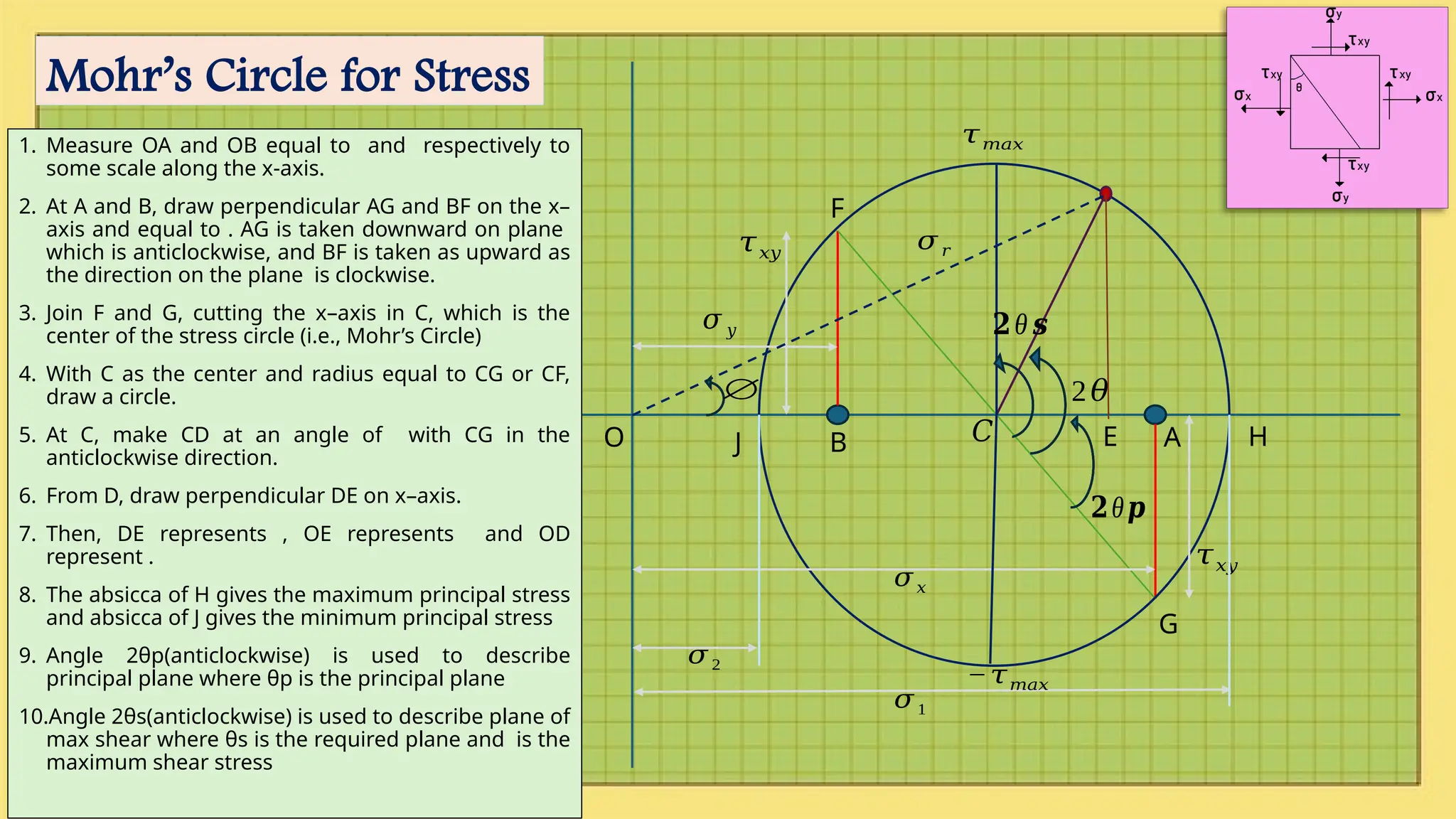
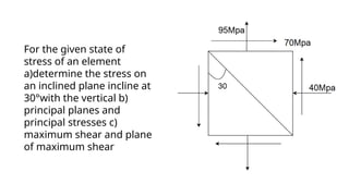
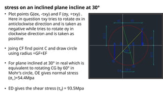
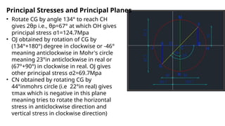
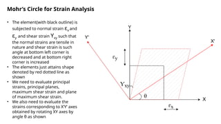
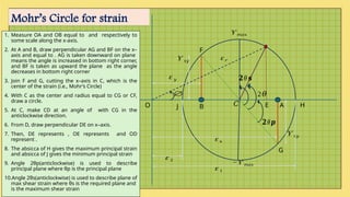
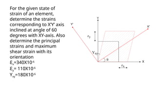
2𝜃
𝜎𝑥
𝜎 𝑦
𝜏𝑥𝑦
𝜏𝑥𝑦
𝜎1
𝜎 2
𝜏𝑚𝑎𝑥
𝐶
−𝜏𝑚𝑎𝑥
𝜎 𝑟
∅
O B A
F
J H
G
E
Mohr’s Circle for Stress
1. Measure OA and OB equal to and respectively to
some scale along the x-axis.
2. At A and B, draw perpendicular AG and BF on the x–
axis and equal to . AG is taken downward on plane
which is anticlockwise, and BF is taken as upward as
the direction on the plane is clockwise.
3. Join F and G, cutting the x–axis in C, which is the
center of the stress circle (i.e., Mohr’s Circle)
4. With C as the center and radius equal to CG or CF,
draw a circle.
5. At C, make CD at an angle of with CG in the
anticlockwise direction.
6. From D, draw perpendicular DE on x–axis.
7. Then, DE represents , OE represents and OD
represent .
8. The absicca of H gives the maximum principal stress
and absicca of J gives the minimum principal stress
9. Angle 2θp(anticlockwise) is used to describe
principal plane where θp is the principal plane
10.Angle 2θs(anticlockwise) is used to describe plane of
max shear where θs is the required plane and is the
maximum shear stress
𝟐θ𝒑
𝟐θ 𝒔
Verification of Mohr’s Circle
Ƴɛθ
For the given state of
stress of an element
a)determine the stress on
an inclined plane incline at
30°with the vertical b)
principal planes and
principal stresses c)
maximum shear and plane
of maximum shear
• Plot points G(σx, -τxy) and F (σy, +τxy) .
Here in question τxy tries to rotate σx in
anticlockwise direction and is taken as
negative while tries to rotate σy in
clockwise direction and is taken as
positive
• Joing CF find point C and draw circle
using radius =GF=EF
• For plane inclined at 30° in real which is
equivalent to rotating CG by 60° in
Mohr’s circle, OE gives normal stress
(σn )=54.4Mpa
• ED gives the shear stress (τθ) = 93.5Mpa
stress on an inclined plane incline at 30°
Principal Stresses and Principal Planes
• Rotate CG by angle 134° to reach CH
gives 2θp i.e., θp=67° at which OH gives
principal stress σ1=124.7Mpa
• OJ obtained by rotation of CG by
(134°+180°) degree in clockwise or -46°
meaning anticlockwise in Mohr's circle
meaning 23°in anticlockwise in real or
(67°+90°) in clockwise in real. OJ gives
other principal stress σ2=69.7Mpa
• CN obtained by rotating CG by
44°inmohrs circle (i.e 22°in real) gives
τmax which is negative in this plane
meaning tries to rotate the horizontal
stress in anticlockwise direction and
vertical stress in clockwise direction)
Mohr’s Circle for Strain Analysis
• The element(with black outline) is
subjected to normal strain ɛx and
ɛy and shear strain Ƴxy such that
the normal strains are tensile in
nature and shear strain is such
angle at bottom left corner is
decreased and at bottom right
corner is increased
• The elements just attains shape
denoted by red dotted line as
shown
• We need to evaluate principal
strains, principal planes,
maximum shear strain and plane
of maximum shear strain.
• We also need to evaluate the
strains corresponding to X’Y’ axes
obtained by rotating XY axes by
angle θ as shown
2𝜃
ɛ 𝑥
ɛ 𝑦
Ƴ 𝑥𝑦
Ƴ 𝑥𝑦
ɛ 1
ɛ 2
Ƴ 𝑚𝑎𝑥
𝐶
−Ƴ 𝑚𝑎𝑥
ɛ 𝑟
∅
O B A
F
J H
G
E
Mohr’s Circle for strain
1. Measure OA and OB equal to and respectively to
some scale along the x-axis.
2. At A and B, draw perpendicular AG and BF on the x–
axis and equal to . AG is taken downward on plane
means the angle is increased in bottom right corner,
and BF is taken as upward the plane as the angle
decreases in bottom right corner
3. Join F and G, cutting the x–axis in C, which is the
center of the strain (i.e., Mohr’s Circle)
4. With C as the center and radius equal to CG or CF,
draw a circle.
5. At C, make CD at an angle of with CG in the
anticlockwise direction.
6. From D, draw perpendicular DE on x–axis.
7. Then, DE represents , OE represents and OD
represent .
8. The absicca of H gives the maximum principal strain
and absicca of J gives the minimum principal strain
9. Angle 2θp(anticlockwise) is used to describe
principal plane where θp is the principal plane
10.Angle 2θs(anticlockwise) is used to describe plane of
max shear strain where θs is the required plane and
is the maximum shear strain
𝟐θ𝒑
𝟐θ 𝒔
For the given state of
strain of an element,
determine the strains
corresponding to X’Y’ axis
inclined at angle of 60
degrees with XY-axis. Also
determine the principal
strains and maximum
shear strain with its
orientation
Ɛx=340X10-6
Ɛy= 110X10-6
Ƴxy=180X10-6
1. Measure OA and OB equal to =340x10-6
and =
110x10-6
respectively to some scale along the
x-axis.
2. At A and B, draw perpendicular AG and BF on
the x–axis and equal to /2= 90x10-6
. AG is taken
downward on plane means the strain tries to
rotate the corresponding axis in anticlockwise
direction, and BF is taken as upward plane
along tries to rotate clockwise
3. Join F and G, cutting the x–axis in C, which is
the center of the strain (i.e., Mohr’s Circle)
4. With C as the center and radius equal to CG or
CF, draw a circle.
5. At C, make CD at an angle of =60° with CG in
the anticlockwise direction.
6. From D, draw perpendicular DE on x–axis.
7. Then, DE represents/2= 55x10-6
, OE
represents=340x10-6
, OL represents=340x10-6
and OD represent =364.17x10⁻⁶
.
8. At 60° the shear stress /2 is observed positive
in the circle which means the plane along tries
to rotate in clockwise and that along tries to
rotate anticlockwise
1.Then, CM represents/2=
146x10-6
, OH
represents=370x10-6
, OJ
represents=340x10-6
2.At angle ACG=38°
,
3. The maximum shear stress /2
is observed positive in the circle
at angle MCG=128° which means
that due to maxm shear strain
the plane along tries to rotate in
clockwise direction and that
along tries to rotate in
anticlockwise direction
2𝜃 𝒑
𝐼𝑥
𝐼 𝑦
𝐼𝑥𝑦
𝐼𝑥𝑦
𝐼𝑚𝑎𝑥
𝐼𝑚𝑖𝑛
𝐶
O B A
F
J H
G
Mohr’s Circle for Principal MOI
1. Measure OA and OB equal to and respectively to
some scale along the x-axis.
2. At A and B, draw perpendicular AG and BF on the x–
axis and equal to . If is positive plot it upwards with
and if negative plot it upwards with
3. Join F and G, cutting the x–axis in C, which is the
center of the strain (i.e., Mohr’s Circle)
4. With C as the center and radius equal to CG or CF,
draw a circle.
5. The absicca of H gives the maximum principal MOI
and absicca of J gives the minimum principal MOI
6. Angle 2θp(anticlockwise +ve)) is used to describe
principal plane where θp is the principal plane
7. In this figure CG is to be rotated clockwise to reach
point H i.e Imax which means the horizontal x-axis is
to be rotated by θp in clockwise to obtain the plane
of maximum MOI in real
𝐼𝑥𝑦
Find the principal
planes and principal
moment of inertia
about the centroidal
axes for the given
built up section
using Mohr’s Circle
𝟓𝟕.𝟕°
𝐼𝑥=1.856 ∗107
𝐼 𝑦=1.46∗107
=3.16*10
𝐼𝑚𝑎𝑥=2.03 ∗107
𝐼𝑚𝑖𝑛=1.28 ∗ 107
𝐶
O B A
F
J H
G
Mohr’s Circle for Principal MOI
1. Measure OA and OB equal to and respectively to
some scale along the x-axis.
2. At A and B, draw perpendicular AG and BF on the x–
axis and equal to . If is positive plot it upwards with
and if negative plot it upwards with
3. Join F and G, cutting the x–axis in C, which is the
center of the strain (i.e., Mohr’s Circle)
4. With C as the center and radius equal to CG or CF,
draw a circle.
5. The absicca of H gives the maximum principal MOI
and absicca of J gives the minimum principal MOI
6. Angle 2θp(anticlockwise +ve)) is used to describe
principal plane where θp is the principal plane
7. In this figure CG is to be rotated clockwise to reach
point H i.e Imax which means the horizontal x-axis is
to be rotated by θp in clockwise to obtain the plane
of maximum MOI in real
8. From the plot, 2θp=-57.7° which means θp=-28.85°
(clockwise)
=3.16*106
Mohr Circle Procedure PPT file - Copy.pptx

Mohr Circle Procedure PPT file - Copy.pptx

  • 1.
    2𝜃 𝜎𝑥 𝜎 𝑦 𝜏𝑥𝑦 𝜏𝑥𝑦 𝜎1 𝜎 2 𝜏𝑚𝑎𝑥 𝐶 −𝜏𝑚𝑎𝑥 𝜎𝑟 ∅ O B A F J H G E Mohr’s Circle for Stress 1. Measure OA and OB equal to and respectively to some scale along the x-axis. 2. At A and B, draw perpendicular AG and BF on the x– axis and equal to . AG is taken downward on plane which is anticlockwise, and BF is taken as upward as the direction on the plane is clockwise. 3. Join F and G, cutting the x–axis in C, which is the center of the stress circle (i.e., Mohr’s Circle) 4. With C as the center and radius equal to CG or CF, draw a circle. 5. At C, make CD at an angle of with CG in the anticlockwise direction. 6. From D, draw perpendicular DE on x–axis. 7. Then, DE represents , OE represents and OD represent . 8. The absicca of H gives the maximum principal stress and absicca of J gives the minimum principal stress 9. Angle 2θp(anticlockwise) is used to describe principal plane where θp is the principal plane 10.Angle 2θs(anticlockwise) is used to describe plane of max shear where θs is the required plane and is the maximum shear stress 𝟐θ𝒑 𝟐θ 𝒔
  • 2.
  • 3.
    For the givenstate of stress of an element a)determine the stress on an inclined plane incline at 30°with the vertical b) principal planes and principal stresses c) maximum shear and plane of maximum shear
  • 4.
    • Plot pointsG(σx, -τxy) and F (σy, +τxy) . Here in question τxy tries to rotate σx in anticlockwise direction and is taken as negative while tries to rotate σy in clockwise direction and is taken as positive • Joing CF find point C and draw circle using radius =GF=EF • For plane inclined at 30° in real which is equivalent to rotating CG by 60° in Mohr’s circle, OE gives normal stress (σn )=54.4Mpa • ED gives the shear stress (τθ) = 93.5Mpa stress on an inclined plane incline at 30°
  • 5.
    Principal Stresses andPrincipal Planes • Rotate CG by angle 134° to reach CH gives 2θp i.e., θp=67° at which OH gives principal stress σ1=124.7Mpa • OJ obtained by rotation of CG by (134°+180°) degree in clockwise or -46° meaning anticlockwise in Mohr's circle meaning 23°in anticlockwise in real or (67°+90°) in clockwise in real. OJ gives other principal stress σ2=69.7Mpa • CN obtained by rotating CG by 44°inmohrs circle (i.e 22°in real) gives τmax which is negative in this plane meaning tries to rotate the horizontal stress in anticlockwise direction and vertical stress in clockwise direction)
  • 6.
    Mohr’s Circle forStrain Analysis • The element(with black outline) is subjected to normal strain ɛx and ɛy and shear strain Ƴxy such that the normal strains are tensile in nature and shear strain is such angle at bottom left corner is decreased and at bottom right corner is increased • The elements just attains shape denoted by red dotted line as shown • We need to evaluate principal strains, principal planes, maximum shear strain and plane of maximum shear strain. • We also need to evaluate the strains corresponding to X’Y’ axes obtained by rotating XY axes by angle θ as shown
  • 7.
    2𝜃 ɛ 𝑥 ɛ 𝑦 Ƴ𝑥𝑦 Ƴ 𝑥𝑦 ɛ 1 ɛ 2 Ƴ 𝑚𝑎𝑥 𝐶 −Ƴ 𝑚𝑎𝑥 ɛ 𝑟 ∅ O B A F J H G E Mohr’s Circle for strain 1. Measure OA and OB equal to and respectively to some scale along the x-axis. 2. At A and B, draw perpendicular AG and BF on the x– axis and equal to . AG is taken downward on plane means the angle is increased in bottom right corner, and BF is taken as upward the plane as the angle decreases in bottom right corner 3. Join F and G, cutting the x–axis in C, which is the center of the strain (i.e., Mohr’s Circle) 4. With C as the center and radius equal to CG or CF, draw a circle. 5. At C, make CD at an angle of with CG in the anticlockwise direction. 6. From D, draw perpendicular DE on x–axis. 7. Then, DE represents , OE represents and OD represent . 8. The absicca of H gives the maximum principal strain and absicca of J gives the minimum principal strain 9. Angle 2θp(anticlockwise) is used to describe principal plane where θp is the principal plane 10.Angle 2θs(anticlockwise) is used to describe plane of max shear strain where θs is the required plane and is the maximum shear strain 𝟐θ𝒑 𝟐θ 𝒔
  • 8.
    For the givenstate of strain of an element, determine the strains corresponding to X’Y’ axis inclined at angle of 60 degrees with XY-axis. Also determine the principal strains and maximum shear strain with its orientation Ɛx=340X10-6 Ɛy= 110X10-6 Ƴxy=180X10-6
  • 9.
    1. Measure OAand OB equal to =340x10-6 and = 110x10-6 respectively to some scale along the x-axis. 2. At A and B, draw perpendicular AG and BF on the x–axis and equal to /2= 90x10-6 . AG is taken downward on plane means the strain tries to rotate the corresponding axis in anticlockwise direction, and BF is taken as upward plane along tries to rotate clockwise 3. Join F and G, cutting the x–axis in C, which is the center of the strain (i.e., Mohr’s Circle) 4. With C as the center and radius equal to CG or CF, draw a circle. 5. At C, make CD at an angle of =60° with CG in the anticlockwise direction. 6. From D, draw perpendicular DE on x–axis. 7. Then, DE represents/2= 55x10-6 , OE represents=340x10-6 , OL represents=340x10-6 and OD represent =364.17x10⁻⁶ . 8. At 60° the shear stress /2 is observed positive in the circle which means the plane along tries to rotate in clockwise and that along tries to rotate anticlockwise
  • 10.
    1.Then, CM represents/2= 146x10-6 ,OH represents=370x10-6 , OJ represents=340x10-6 2.At angle ACG=38° , 3. The maximum shear stress /2 is observed positive in the circle at angle MCG=128° which means that due to maxm shear strain the plane along tries to rotate in clockwise direction and that along tries to rotate in anticlockwise direction
  • 11.
    2𝜃 𝒑 𝐼𝑥 𝐼 𝑦 𝐼𝑥𝑦 𝐼𝑥𝑦 𝐼𝑚𝑎𝑥 𝐼𝑚𝑖𝑛 𝐶 OB A F J H G Mohr’s Circle for Principal MOI 1. Measure OA and OB equal to and respectively to some scale along the x-axis. 2. At A and B, draw perpendicular AG and BF on the x– axis and equal to . If is positive plot it upwards with and if negative plot it upwards with 3. Join F and G, cutting the x–axis in C, which is the center of the strain (i.e., Mohr’s Circle) 4. With C as the center and radius equal to CG or CF, draw a circle. 5. The absicca of H gives the maximum principal MOI and absicca of J gives the minimum principal MOI 6. Angle 2θp(anticlockwise +ve)) is used to describe principal plane where θp is the principal plane 7. In this figure CG is to be rotated clockwise to reach point H i.e Imax which means the horizontal x-axis is to be rotated by θp in clockwise to obtain the plane of maximum MOI in real 𝐼𝑥𝑦
  • 12.
    Find the principal planesand principal moment of inertia about the centroidal axes for the given built up section using Mohr’s Circle
  • 13.
    𝟓𝟕.𝟕° 𝐼𝑥=1.856 ∗107 𝐼 𝑦=1.46∗107 =3.16*10 𝐼𝑚𝑎𝑥=2.03∗107 𝐼𝑚𝑖𝑛=1.28 ∗ 107 𝐶 O B A F J H G Mohr’s Circle for Principal MOI 1. Measure OA and OB equal to and respectively to some scale along the x-axis. 2. At A and B, draw perpendicular AG and BF on the x– axis and equal to . If is positive plot it upwards with and if negative plot it upwards with 3. Join F and G, cutting the x–axis in C, which is the center of the strain (i.e., Mohr’s Circle) 4. With C as the center and radius equal to CG or CF, draw a circle. 5. The absicca of H gives the maximum principal MOI and absicca of J gives the minimum principal MOI 6. Angle 2θp(anticlockwise +ve)) is used to describe principal plane where θp is the principal plane 7. In this figure CG is to be rotated clockwise to reach point H i.e Imax which means the horizontal x-axis is to be rotated by θp in clockwise to obtain the plane of maximum MOI in real 8. From the plot, 2θp=-57.7° which means θp=-28.85° (clockwise) =3.16*106