This document outlines the syllabus for the module "Theory & Design of Structures". It includes:
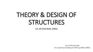
1) An allocation of 72 hours for lectures, 0 hours for tutorials, 38 hours for practical demonstrations/industrial visits, and 110 hours for self-study.
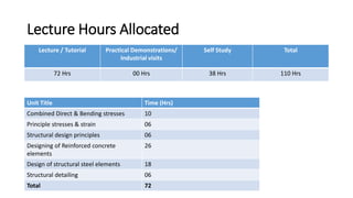
2) A breakdown of the module content into units on combined direct & bending stresses, principle stresses & strains, structural design principles, designing reinforced concrete and structural steel elements, and structural detailing.
3) The aim of the module is to develop an understanding of structural behavior and design principles for statically determinate civil engineering structures.


![STEPS: Mohr Circle Method
• In order to do achieve the desired objective we proceed in the following manner
(i) Label the Block ABCD.
(ii) Set up axes for the direct stress (as abscissa/ X axis) and shear stress (as
Ordinate/ Y axis)
(iii) Plot the stresses on two adjacent faces e.g. AB and BC, using the following
sign convention.
• Direct stresses : Tensile positive;
Compressive, negative
• Shear stresses : Tending to turn block clockwise Positive,
Tending to turn block counter clockwise, negative
• [ i.e shearing stresses are +ve when its movement about the Centre of the
element is clockwise ]](https://image.slidesharecdn.com/tdslec4-231104121854-cbae7804/85/TDS-Lec-4-pptx-8-320.jpg)


![Further points to be noted are :
(1) The direct stress is maximum when Q is at M and at this point obviously the
sheer stress is zero,
• Hence by definition OM is the length representing the maximum principal
stresses σ1 and 2ϴ1 gives the angle of the plane 1 from BC.
• Similar OL is the other principal stress and is represented by σ2
(2) The maximum shear stress is given by the highest point on the circle and is
represented by the radius of the circle.
This follows that since shear stresses and complimentary sheer stresses have the
same value; therefore the center of the circle will always lie on the X axis midway
between x and y .
[ since +τxy & - τxy are shear stress & complimentary shear stress so they are same
in magnitude but different in sign. ]](https://image.slidesharecdn.com/tdslec4-231104121854-cbae7804/85/TDS-Lec-4-pptx-14-320.jpg)


