Downloaded 37 times

![@FORMULA@
MAX. PRINCIPLE STRESS=>
(X+Y)/2+[{(X-Y)/2}^2+(Zxy)^2]^(.5)=C+R
MIN. PRINCIPLE STRESS=>
(X+Y)/2-[{(X-Y)/2}^2+(Zxy)^2]^(.5)=C-R
COORDINATE(C)=(X+Y)/2
RADIUS OF CIRCLE(R)=[{(X-Y)/2}^2+(Zxy)^2]^(.5)
Where X=Stress in x-direction, Y=Stress in y-
direction and Zxy=Shear stress.](https://image.slidesharecdn.com/mohrscircle-samriddha1-170506102814/85/Mohr-s-circle-Samriddha-Shil-S-S-3-320.jpg)
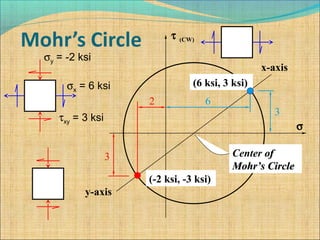
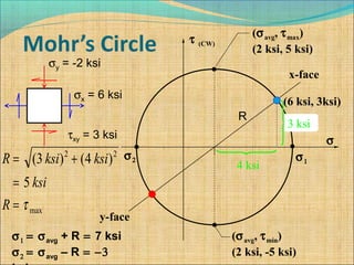
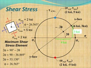
![σavg = 2 ksi
σavg = 2 ksi
τmax = 5 ksi
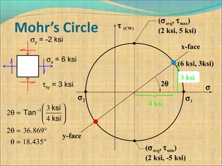
φ = 26.565°
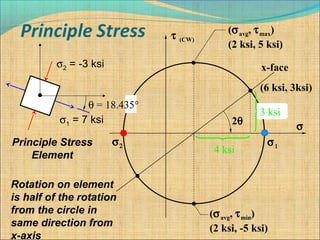
σ1 = 7 ksi
σ2 = -3 ksi
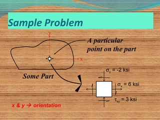
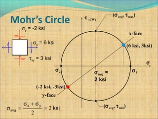
σx = 6 ksi
σy = -2 ksi
τxy = 3 ksi
θ = 18.435°
θ+ φ = 18.435 ° + 26.565 ° = 45 °,[Z=(X1-Y1)/2 sin2#+Zxy cos2#],
Where #=45*, Now we get Zmax=(X1-Y1)/2.](https://image.slidesharecdn.com/mohrscircle-samriddha1-170506102814/85/Mohr-s-circle-Samriddha-Shil-S-S-11-320.jpg)

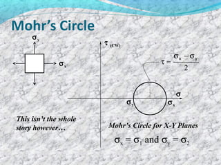
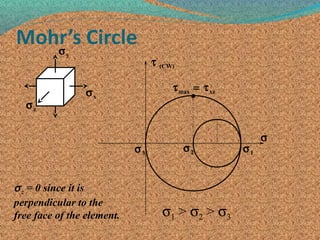


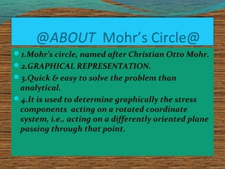
1. Mohr's circle is a graphical representation used to determine stress components acting on a rotated plane passing through a point on a part. 2. It relates normal and shear stresses on the original x-y plane to those on a rotated plane using equations that define a circle. 3. Key values like maximum and minimum principal stresses that correspond to points on the circle can be read off to understand how stress changes with rotation.