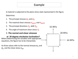
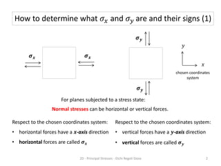
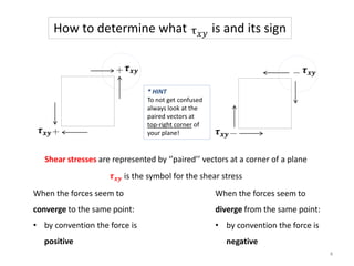
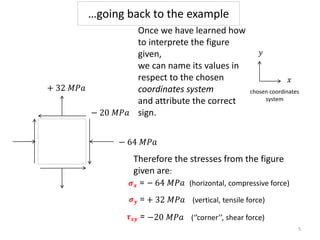
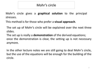
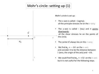
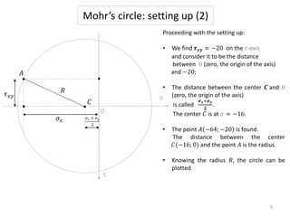
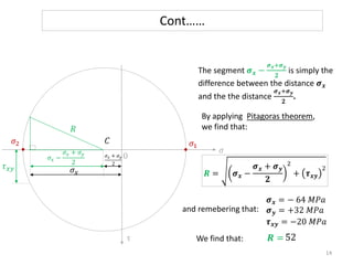
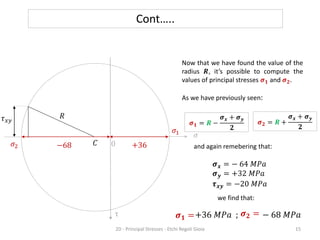
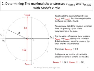
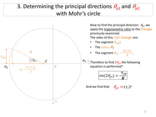
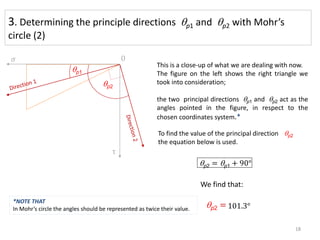
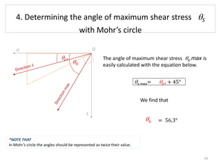
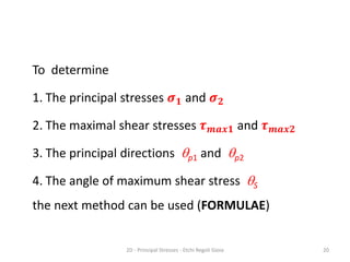
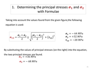
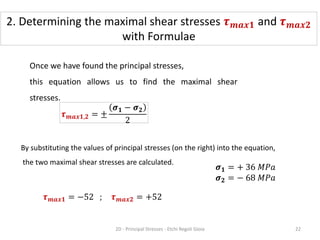
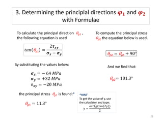
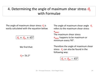
A material is subjected to the plane stress state represented in the figure.
Determine:
1. The principal stresses 𝝈𝟏 and 𝝈𝟐
2. The maximal shear stresses 𝝉𝒎𝒂𝒙𝟏 and 𝝉𝒎𝒂𝒙𝟐
3. The principal directions qp1 and qp2
4. The angle of maximum shear stress qs
5. The normal and shear stresses
at 30 degree clockwise inclination?
Example
Before determining the variables with appropriate
equations, the figure has to be interpreted;
Its three values refer to the normal stresses 𝝈𝒙 and
𝝈𝒚 and the shear stress 𝝉𝒙𝒚.
32 𝑀𝑃𝑎
64 𝑀𝑃𝑎
20 𝑀𝑃𝑎
1
Normal stresses can be horizontal or vertical forces.
Respect to the chosen coordinates system:
• horizontal forces have a 𝒙-axis direction
• horizontal forces are called 𝝈𝒙
Respect to the chosen coordinates system:
• vertical forces have a 𝒚-axis direction
• vertical forces are called 𝝈𝒚
𝝈𝒙 𝝈𝒙
𝝈𝒚
𝝈𝒚
For planes subjected to a stress state:
chosen coordinates
system
𝑥
𝑦
How to determine what 𝜎𝑥 and 𝜎𝑦 are and their signs (1)
2D - Principal Stresses - Etchi Regoli Gioia 2
Horizontal and vertical forces seem
to converge on the same point
• this leads to a compression
• the forces are negative
Horizontal and vertical forces seem
to diverge from the same point
• this leads to a tension
• the forces are positive
How to determine what 𝜎𝑥 and 𝜎𝑦 are and their signs (2)
3
How to determine what is and its sign
When the forces seem to
converge to the same point:
• by convention the force is
positive
When the forces seem to
diverge from the same point:
• by convention the force is
negative
* HINT
To not get confused
always look at the
paired vectors at
top-right corner of
your plane!
Shear stresses are represented by ‘’paired’’ vectors at a corner of a plane
𝝉𝒙𝒚 is the symbol for the shear stress
𝝉𝒙𝒚
𝝉𝒙𝒚 𝝉𝒙𝒚
𝝉𝒙𝒚
4
𝝈𝒙 = − 64 𝑀𝑃𝑎 (horizontal, compressive force)
𝝈𝒚 = + 32 𝑀𝑃𝑎 (vertical, tensile force)
𝝉𝒙𝒚 = −20 𝑀𝑃𝑎 (‘’corner’’, shear force)
…going back to the example
Once we have learned how
to interprete the figure
given,
we can name its values in
respect to the chosen
coordinates system
and attribute the correct
sign.
chosen coordinates
system
𝑥
𝑦
+ 32 𝑀𝑃𝑎
− 64 𝑀𝑃𝑎
− 20 𝑀𝑃𝑎
Therefore the stresses from the figure
given are:
𝝈𝒙 =
𝝈𝒚 =
𝝉𝒙𝒚 =
5
3 Different methods
Now that we have understood the figure given, we can
answer the four initial questions of the problem.
To do that,
3 different methods can be used:
• MOHR’S CIRCLE
• FORMULAE
• MATRICES AND DETERMINANTS
Despite their diversity, they are all mathematical methods
and they all have to lead to the same answer.
6
Mohr’s circle
Mohr’s circle gives a graphical solution to the principal
stresses.
This method is for those who prefer a visual approach.
The set up of Mohr’s circle will be explained over the next three
slides.
The set up is really a demonstration of the derived equations;
once the demonstration is clear, the setting up is not necessary
anymore.
In the other lecture notes we are still going to deal Mohr’s circle,
but the use of the equations will be enough for the building of the
circle.
7
Mohr’s circle: setting up (1)
τ
𝜎𝑥
𝐶
0 𝜎
Mohr’s circle is set up:
• The 𝑥-axis is called 𝜎 (sigma);
all the principle stresses lie on the 𝜎-axis;
• The 𝑦-axis is called τ (tau) and it points
downwards;
all the shear stresses lie on the points of
the circle;
• The center 𝑪 always lies on the 𝜎-axis;
• We find 𝝈𝒙 = − 64 on the 𝜎-axis
and consider it to be the distance between
0 (zero, the origin of the axis) and −64;
• We could find find 𝝈𝒚 = +32 on the 𝜎-axis
but it is not useful for the following steps.
8
Mohr’s circle: setting up (2)
𝜎𝑥
𝜏𝑥𝑦
𝜎𝑥 + 𝜎𝑦
2
𝐶
0
𝜎
Proceeding with the setting up:
• We find 𝝉𝒙𝒚 = −20 on the τ-axis
and consider it to be the distance
between 0 (zero, the origin of the axis)
and −20;
• The distance between the center 𝑪 and 0
(zero, the origin of the axis)
is called
𝝈𝒙+𝝈𝒚
𝟐
.
The center 𝐶 is at 𝜎 = −16.
• The point 𝐴 −64; −20 is found.
The distance between the center
𝐶(−16; 0) and the point 𝐴 is the radius.
• Knowing the radius 𝑅, the circle can be
plotted
𝑅
𝐴
9
τ
Mohr’s circle: setting up (2)
Let’s now focus on the four initial
questions of the problem.
In Mohr’s circle:
• The values of the principal stresses
𝝈𝟏 and 𝝈𝟐 are determined by the
interceptions of the circle with the
𝜎-axis ;
• the values of shear stresses 𝝉𝒎𝒂𝒙𝟏
and 𝝉𝒎𝒂𝒙𝟐 are determined by the
intersection of the circle with the
diameter parallel to the 𝜏-axis;
• The value of the principal direction
qp1 is given by the angle between
the 𝜎-axis
and the radius 𝑹 of the circle
. that we call 𝟐qp1 for convenience.
𝜎𝑥
𝜏𝑥𝑦
𝜎𝑥 + 𝜎𝑦
2
𝐶
0 𝜎
𝜏𝑚𝑎𝑥2
𝜏𝑚𝑎𝑥1
𝜎1
𝜎2
𝑅
2qp1
10
τ
Determining:
1. The principal stresses 𝝈𝟏 and 𝝈𝟐
2. The maximal shear stresses 𝝉𝒎𝒂𝒙𝟏 and 𝝉𝒎𝒂𝒙𝟐
3. The principal directions qp1 and qp2
4. The angle of maximum shear stress qS
With MOHR’S CIRCLE
2D - Principal Stresses - Etchi Regoli Gioia 11
To find the values of principal
stresses 𝝈𝟏 and 𝝈𝟐, the distances
between 0 (zero, the origin of the
axis) and the points 𝝈𝟏 and 𝝈𝟐 have
to be determined .
As the radius 𝑹 is the distance
between the center 𝑪 and any
point of the circumference,
it can be seen that:
𝝈𝟏 = 𝑹 −
𝝈𝒙 + 𝝈𝒚
𝟐
𝛔𝟐 = 𝑹 +
𝝈𝒙 + 𝝈𝒚
𝟐
𝜎𝑥 + 𝜎𝑦
2
𝜎
𝑅
𝜎𝑥
0
𝜏𝑥𝑦
𝜎1
𝜎2
1. Determining the principle stresses 𝜎1 and 𝜎2
with Mohr’s circle (1)
12
τ
𝐶
𝑅
𝜎𝑥 + 𝜎𝑦
2
𝜎
𝜎𝑥
0
𝜎𝑥 −
𝜎𝑥 + 𝜎𝑦
2
𝜏𝑥𝑦
𝜎1
𝜎2
Cont….
Now to find the radius 𝑅 we apply
Pitagoras theorem* to the highlited
triangle.
The sides of this right triangle are:
• The segment 𝝉𝒙𝒚;
• The radius 𝑹;
• The segment 𝝈𝒙 −
𝝈𝒙+𝝈𝒚
𝟐
.
*HINT: Pitagora’s theorem
𝑎 𝑐
𝑐2
= 𝑎2 + 𝑏2
𝑏2
= 𝑐2 − 𝑎2
𝑎2
= 𝑐2 −𝑏2
13
τ
𝑅
𝐶
and remebering that:
We find that:
𝜎𝑥 + 𝜎𝑦
2
𝜎
𝜎𝑥
0
𝜎𝑥 −
𝜎𝑥 + 𝜎𝑦
2
𝜏𝑥𝑦
𝜎1
𝜎2
The segment 𝝈𝒙 −
𝝈𝒙+𝝈𝒚
𝟐
is simply the
difference between the distance 𝝈𝒙
and the the distance
𝝈𝒙+𝝈𝒚
𝟐
.
𝑹 = 𝝈𝒙 −
𝝈𝒙 + 𝝈𝒚
𝟐
2
+ 𝝉𝒙𝒚
2
𝝈𝒙 = − 64 𝑀𝑃𝑎
𝝈𝒚 = +32 𝑀𝑃𝑎
𝝉𝒙𝒚 = −20 𝑀𝑃𝑎
𝑹 =
Cont……
52
By applying Pitagoras theorem,
we find that:
14
τ
𝑅
𝐶
− 68 𝑀𝑃𝑎
and again remebering that:
we find that:
𝜎
0
𝜏𝑥𝑦
𝜎1
𝜎2
𝝈𝒙 = − 64 𝑀𝑃𝑎
𝝈𝒚 = +32 𝑀𝑃𝑎
𝝉𝒙𝒚 = −20 𝑀𝑃𝑎
𝝈𝟏 =
Now that we have found the value of the
radius 𝑹, it’s possible to compute the
values of principal stresses 𝝈𝟏 and 𝝈𝟐.
As we have previously seen:
𝝈𝟏 = 𝑹 −
𝝈𝒙 + 𝝈𝒚
𝟐
𝝈𝟐 = 𝑹 +
𝝈𝒙 + 𝝈𝒚
𝟐
Cont…..
−68 +36
𝑅
𝐶
𝝈𝟐 =
+36 𝑀𝑃𝑎 ;
2D - Principal Stresses - Etchi Regoli Gioia 15
τ
τ
τ
τ
τ
𝜎
0
𝜏𝑥𝑦
𝜎1
𝜎2
To calculate the maximal shear stresses
𝝉𝒎𝒂𝒙𝟏 and 𝝉𝒎𝒂𝒙𝟐, the distances pointed in
the figure have to be found.
As previously stated the values of any shear
force 𝝉 is given by a point of the
circumference of the circle.
And the values of maximal shear stresses
𝝉𝒎𝒂𝒙𝟏 and 𝝉𝒎𝒂𝒙𝟐 are equal to the radius
𝑹, being distances from the center of the
circle and the circumference.
Therefore: 𝝉𝒎𝒂𝒙𝟏,𝟐 = 52
But because we need to stick with the
chosen coordinates system, the result is:
𝜏𝑚𝑎𝑥2
𝜏𝑚𝑎𝑥1
+52
−52
2. Determining The maximal shear stresses 𝜏𝑚𝑎𝑥1 and 𝜏𝑚𝑎𝑥2
with Mohr’s circle
𝝉𝒎𝒂𝒙𝟏 = −52
𝝉𝒎𝒂𝒙𝟐 =
+52 ;
2D - Principal Stresses - Etchi Regoli Gioia 16
τ
𝑅
𝐶
3. Determining the principal directions qp1 and qp2
with Mohr’s circle
𝜎
2qp11
0
𝜏𝑥𝑦
𝜎1
𝜎2
Now to find the principal direction qp1 we
apply the trigonometric ratio to the triangle
previously examined.
The sides of this right triangle are:
• The segment 𝝉𝒙𝒚;
• The radius 𝑹;
• The segment 𝝈𝒙 −
𝝈𝒙+𝝈𝒚
𝟐
.
Therefore to find 2qp1 the following
equation is performed*
𝜎𝑥 −
𝜎𝑥 + 𝜎𝑦
2
𝑅
sin(2qp1) =
𝝉𝒙𝒚
𝑹
And we find that qp1 =11.3°
17
τ
𝐶
3. Determining the principle directions qp1 and qp2 with Mohr’s
circle (2)
qp1
qp2
To find the value of the principal direction qp2
the equation below is used.
qp2 = qp1 + 90°
qp2 =
This is a close-up of what we are dealing with now.
The figure on the left shows the right triangle we
took into consideration;
the two principal directions qp1 and qp2 act as the
angles pointed in the figure, in respect to the
chosen coordinates system.*
We find that:
𝜎
τ
0
101.3°
18
*NOTE THAT
In Mohr’s circle the angles should be represented as twice their value.
qp1
qS
𝜎
τ
0
The angle of maximum shear stress qs.max is
easily calculated with the equation below.
qs.max= qp1 + 45°
qs.
We find that
= 56.3°
4. Determining the angle of maximum shear stress qS
with Mohr’s circle
19
*NOTE THAT
In Mohr’s circle the angles should be represented as twice their value.
To determine
1. The principal stresses 𝝈𝟏 and 𝝈𝟐
2. The maximal shear stresses 𝝉𝒎𝒂𝒙𝟏 and 𝝉𝒎𝒂𝒙𝟐
3. The principal directions qp1 and qp2
4. The angle of maximum shear stress qS
the next method can be used (FORMULAE)
2D - Principal Stresses - Etchi Regoli Gioia 20
Taking into account the values found from the given figure,the following
equation is used:
By substituting the values of principal stresses (on the right) into the equation,
the two principal stresses are found.
𝝈𝟏 = +36 𝑀𝑃𝑎
𝝈𝟐 = − 68 𝑀𝑃𝑎
𝝈𝒙 = − 64 𝑀𝑃𝑎
𝝈𝒚 = +32 𝑀𝑃𝑎
𝝉𝒙𝒚 = −20 𝑀𝑃𝑎
𝝈𝟏,𝟐 =
𝝈𝒙 + 𝝈𝒚
2
±
𝝈𝒙 − 𝝈𝒚
2
2
+ 𝝉𝒙𝒚
2
1. Determining the principal stresses 𝝈𝟏 and 𝝈𝟐
with Formulae
21
Once we have found the principal stresses,
this equation allows us to find the maximal shear
stresses.
By substituting the values of principal stresses (on the right) into the equation,
the two maximal shear stresses are calculated.
𝝉𝒎𝒂𝒙𝟏,𝟐 = ±
𝝈𝟏 − 𝝈𝟐
2
𝝉𝒎𝒂𝒙𝟏 = −52 ; 𝝉𝒎𝒂𝒙𝟐 = +52
𝝈𝟏 = + 36 𝑀𝑃𝑎
𝝈𝟐 = − 68 𝑀𝑃𝑎
2. Determining the maximal shear stresses 𝝉𝒎𝒂𝒙𝟏 and 𝝉𝒎𝒂𝒙𝟐
with Formulae
2D - Principal Stresses - Etchi Regoli Gioia 22
𝑡𝑎𝑛 qp1 =
2𝝉𝒙𝒚
𝝈𝒙 − 𝝈𝒚
To calculate the principal direction qp1 ,
the following equation is used
By substituting the values below:
the principal stress qp1 is found:*
qp1 = 11.3°
*HINT
To get the value of y, use
the calculator and type:
𝑦 =
𝑎𝑟𝑐𝑡𝑔(tan 2𝑦 )
2
𝝈𝒙 = − 64 𝑀𝑃𝑎
𝝈𝒚 = +32 𝑀𝑃𝑎
𝝉𝒙𝒚 = −20 𝑀𝑃𝑎
3. Determining the principlal directions 𝝋𝟏 and 𝝋𝟐
with Formulae
To compute the principal stress
qp2 the equation below is used.
qp2 = qp1 + 90°
qp2= 101.3°
And we find that:
23
The angle of maximum shear stress qs is
easily calculated with the equation below.
qs = qp1 + 45°
qs= 56.3°
The angle of maximum shear angle qs
refers to the maximum shear stress
𝝉𝒎𝒂𝒙.
The maximum shear stress
𝝉𝒎𝒂𝒙 happens to be maximum or
minimum every 90°.
Therefore the angle of maximum shear
stress qs can also be found in the
following way:
qs = qp2 − 45°
We find that:
4. Determining the angle of maximum shear stress qS
with Formulae
2D - Principal Stresses - Etchi Regoli Gioia 24
25
REFERENCES:
• Websites:http://web.mst.edu/~mecmovie/
• Textbooks: Hibbeler, R. C., 2014. Statics and mechanics of materials. 4th ed. Cape
Town, Singapore: Pearson Education South Asia
• Lecture notes: DEN4102-12-Multi-dimensional Stress and Strain
by Professor Emiliano Bilotti

chp 4 Example.pptx

  • 1.
    A material issubjected to the plane stress state represented in the figure. Determine: 1. The principal stresses 𝝈𝟏 and 𝝈𝟐 2. The maximal shear stresses 𝝉𝒎𝒂𝒙𝟏 and 𝝉𝒎𝒂𝒙𝟐 3. The principal directions qp1 and qp2 4. The angle of maximum shear stress qs 5. The normal and shear stresses at 30 degree clockwise inclination? Example Before determining the variables with appropriate equations, the figure has to be interpreted; Its three values refer to the normal stresses 𝝈𝒙 and 𝝈𝒚 and the shear stress 𝝉𝒙𝒚. 32 𝑀𝑃𝑎 64 𝑀𝑃𝑎 20 𝑀𝑃𝑎 1
  • 2.
    Normal stresses canbe horizontal or vertical forces. Respect to the chosen coordinates system: • horizontal forces have a 𝒙-axis direction • horizontal forces are called 𝝈𝒙 Respect to the chosen coordinates system: • vertical forces have a 𝒚-axis direction • vertical forces are called 𝝈𝒚 𝝈𝒙 𝝈𝒙 𝝈𝒚 𝝈𝒚 For planes subjected to a stress state: chosen coordinates system 𝑥 𝑦 How to determine what 𝜎𝑥 and 𝜎𝑦 are and their signs (1) 2D - Principal Stresses - Etchi Regoli Gioia 2
  • 3.
    Horizontal and verticalforces seem to converge on the same point • this leads to a compression • the forces are negative Horizontal and vertical forces seem to diverge from the same point • this leads to a tension • the forces are positive How to determine what 𝜎𝑥 and 𝜎𝑦 are and their signs (2) 3
  • 4.
    How to determinewhat is and its sign When the forces seem to converge to the same point: • by convention the force is positive When the forces seem to diverge from the same point: • by convention the force is negative * HINT To not get confused always look at the paired vectors at top-right corner of your plane! Shear stresses are represented by ‘’paired’’ vectors at a corner of a plane 𝝉𝒙𝒚 is the symbol for the shear stress 𝝉𝒙𝒚 𝝉𝒙𝒚 𝝉𝒙𝒚 𝝉𝒙𝒚 4
  • 5.
    𝝈𝒙 = −64 𝑀𝑃𝑎 (horizontal, compressive force) 𝝈𝒚 = + 32 𝑀𝑃𝑎 (vertical, tensile force) 𝝉𝒙𝒚 = −20 𝑀𝑃𝑎 (‘’corner’’, shear force) …going back to the example Once we have learned how to interprete the figure given, we can name its values in respect to the chosen coordinates system and attribute the correct sign. chosen coordinates system 𝑥 𝑦 + 32 𝑀𝑃𝑎 − 64 𝑀𝑃𝑎 − 20 𝑀𝑃𝑎 Therefore the stresses from the figure given are: 𝝈𝒙 = 𝝈𝒚 = 𝝉𝒙𝒚 = 5
  • 6.
    3 Different methods Nowthat we have understood the figure given, we can answer the four initial questions of the problem. To do that, 3 different methods can be used: • MOHR’S CIRCLE • FORMULAE • MATRICES AND DETERMINANTS Despite their diversity, they are all mathematical methods and they all have to lead to the same answer. 6
  • 7.
    Mohr’s circle Mohr’s circlegives a graphical solution to the principal stresses. This method is for those who prefer a visual approach. The set up of Mohr’s circle will be explained over the next three slides. The set up is really a demonstration of the derived equations; once the demonstration is clear, the setting up is not necessary anymore. In the other lecture notes we are still going to deal Mohr’s circle, but the use of the equations will be enough for the building of the circle. 7
  • 8.
    Mohr’s circle: settingup (1) τ 𝜎𝑥 𝐶 0 𝜎 Mohr’s circle is set up: • The 𝑥-axis is called 𝜎 (sigma); all the principle stresses lie on the 𝜎-axis; • The 𝑦-axis is called τ (tau) and it points downwards; all the shear stresses lie on the points of the circle; • The center 𝑪 always lies on the 𝜎-axis; • We find 𝝈𝒙 = − 64 on the 𝜎-axis and consider it to be the distance between 0 (zero, the origin of the axis) and −64; • We could find find 𝝈𝒚 = +32 on the 𝜎-axis but it is not useful for the following steps. 8
  • 9.
    Mohr’s circle: settingup (2) 𝜎𝑥 𝜏𝑥𝑦 𝜎𝑥 + 𝜎𝑦 2 𝐶 0 𝜎 Proceeding with the setting up: • We find 𝝉𝒙𝒚 = −20 on the τ-axis and consider it to be the distance between 0 (zero, the origin of the axis) and −20; • The distance between the center 𝑪 and 0 (zero, the origin of the axis) is called 𝝈𝒙+𝝈𝒚 𝟐 . The center 𝐶 is at 𝜎 = −16. • The point 𝐴 −64; −20 is found. The distance between the center 𝐶(−16; 0) and the point 𝐴 is the radius. • Knowing the radius 𝑅, the circle can be plotted 𝑅 𝐴 9 τ
  • 10.
    Mohr’s circle: settingup (2) Let’s now focus on the four initial questions of the problem. In Mohr’s circle: • The values of the principal stresses 𝝈𝟏 and 𝝈𝟐 are determined by the interceptions of the circle with the 𝜎-axis ; • the values of shear stresses 𝝉𝒎𝒂𝒙𝟏 and 𝝉𝒎𝒂𝒙𝟐 are determined by the intersection of the circle with the diameter parallel to the 𝜏-axis; • The value of the principal direction qp1 is given by the angle between the 𝜎-axis and the radius 𝑹 of the circle . that we call 𝟐qp1 for convenience. 𝜎𝑥 𝜏𝑥𝑦 𝜎𝑥 + 𝜎𝑦 2 𝐶 0 𝜎 𝜏𝑚𝑎𝑥2 𝜏𝑚𝑎𝑥1 𝜎1 𝜎2 𝑅 2qp1 10 τ
  • 11.
    Determining: 1. The principalstresses 𝝈𝟏 and 𝝈𝟐 2. The maximal shear stresses 𝝉𝒎𝒂𝒙𝟏 and 𝝉𝒎𝒂𝒙𝟐 3. The principal directions qp1 and qp2 4. The angle of maximum shear stress qS With MOHR’S CIRCLE 2D - Principal Stresses - Etchi Regoli Gioia 11
  • 12.
    To find thevalues of principal stresses 𝝈𝟏 and 𝝈𝟐, the distances between 0 (zero, the origin of the axis) and the points 𝝈𝟏 and 𝝈𝟐 have to be determined . As the radius 𝑹 is the distance between the center 𝑪 and any point of the circumference, it can be seen that: 𝝈𝟏 = 𝑹 − 𝝈𝒙 + 𝝈𝒚 𝟐 𝛔𝟐 = 𝑹 + 𝝈𝒙 + 𝝈𝒚 𝟐 𝜎𝑥 + 𝜎𝑦 2 𝜎 𝑅 𝜎𝑥 0 𝜏𝑥𝑦 𝜎1 𝜎2 1. Determining the principle stresses 𝜎1 and 𝜎2 with Mohr’s circle (1) 12 τ 𝐶 𝑅
  • 13.
    𝜎𝑥 + 𝜎𝑦 2 𝜎 𝜎𝑥 0 𝜎𝑥− 𝜎𝑥 + 𝜎𝑦 2 𝜏𝑥𝑦 𝜎1 𝜎2 Cont…. Now to find the radius 𝑅 we apply Pitagoras theorem* to the highlited triangle. The sides of this right triangle are: • The segment 𝝉𝒙𝒚; • The radius 𝑹; • The segment 𝝈𝒙 − 𝝈𝒙+𝝈𝒚 𝟐 . *HINT: Pitagora’s theorem 𝑎 𝑐 𝑐2 = 𝑎2 + 𝑏2 𝑏2 = 𝑐2 − 𝑎2 𝑎2 = 𝑐2 −𝑏2 13 τ 𝑅 𝐶
  • 14.
    and remebering that: Wefind that: 𝜎𝑥 + 𝜎𝑦 2 𝜎 𝜎𝑥 0 𝜎𝑥 − 𝜎𝑥 + 𝜎𝑦 2 𝜏𝑥𝑦 𝜎1 𝜎2 The segment 𝝈𝒙 − 𝝈𝒙+𝝈𝒚 𝟐 is simply the difference between the distance 𝝈𝒙 and the the distance 𝝈𝒙+𝝈𝒚 𝟐 . 𝑹 = 𝝈𝒙 − 𝝈𝒙 + 𝝈𝒚 𝟐 2 + 𝝉𝒙𝒚 2 𝝈𝒙 = − 64 𝑀𝑃𝑎 𝝈𝒚 = +32 𝑀𝑃𝑎 𝝉𝒙𝒚 = −20 𝑀𝑃𝑎 𝑹 = Cont…… 52 By applying Pitagoras theorem, we find that: 14 τ 𝑅 𝐶
  • 15.
    − 68 𝑀𝑃𝑎 andagain remebering that: we find that: 𝜎 0 𝜏𝑥𝑦 𝜎1 𝜎2 𝝈𝒙 = − 64 𝑀𝑃𝑎 𝝈𝒚 = +32 𝑀𝑃𝑎 𝝉𝒙𝒚 = −20 𝑀𝑃𝑎 𝝈𝟏 = Now that we have found the value of the radius 𝑹, it’s possible to compute the values of principal stresses 𝝈𝟏 and 𝝈𝟐. As we have previously seen: 𝝈𝟏 = 𝑹 − 𝝈𝒙 + 𝝈𝒚 𝟐 𝝈𝟐 = 𝑹 + 𝝈𝒙 + 𝝈𝒚 𝟐 Cont….. −68 +36 𝑅 𝐶 𝝈𝟐 = +36 𝑀𝑃𝑎 ; 2D - Principal Stresses - Etchi Regoli Gioia 15 τ
  • 16.
    τ τ τ τ 𝜎 0 𝜏𝑥𝑦 𝜎1 𝜎2 To calculate themaximal shear stresses 𝝉𝒎𝒂𝒙𝟏 and 𝝉𝒎𝒂𝒙𝟐, the distances pointed in the figure have to be found. As previously stated the values of any shear force 𝝉 is given by a point of the circumference of the circle. And the values of maximal shear stresses 𝝉𝒎𝒂𝒙𝟏 and 𝝉𝒎𝒂𝒙𝟐 are equal to the radius 𝑹, being distances from the center of the circle and the circumference. Therefore: 𝝉𝒎𝒂𝒙𝟏,𝟐 = 52 But because we need to stick with the chosen coordinates system, the result is: 𝜏𝑚𝑎𝑥2 𝜏𝑚𝑎𝑥1 +52 −52 2. Determining The maximal shear stresses 𝜏𝑚𝑎𝑥1 and 𝜏𝑚𝑎𝑥2 with Mohr’s circle 𝝉𝒎𝒂𝒙𝟏 = −52 𝝉𝒎𝒂𝒙𝟐 = +52 ; 2D - Principal Stresses - Etchi Regoli Gioia 16 τ 𝑅 𝐶
  • 17.
    3. Determining theprincipal directions qp1 and qp2 with Mohr’s circle 𝜎 2qp11 0 𝜏𝑥𝑦 𝜎1 𝜎2 Now to find the principal direction qp1 we apply the trigonometric ratio to the triangle previously examined. The sides of this right triangle are: • The segment 𝝉𝒙𝒚; • The radius 𝑹; • The segment 𝝈𝒙 − 𝝈𝒙+𝝈𝒚 𝟐 . Therefore to find 2qp1 the following equation is performed* 𝜎𝑥 − 𝜎𝑥 + 𝜎𝑦 2 𝑅 sin(2qp1) = 𝝉𝒙𝒚 𝑹 And we find that qp1 =11.3° 17 τ 𝐶
  • 18.
    3. Determining theprinciple directions qp1 and qp2 with Mohr’s circle (2) qp1 qp2 To find the value of the principal direction qp2 the equation below is used. qp2 = qp1 + 90° qp2 = This is a close-up of what we are dealing with now. The figure on the left shows the right triangle we took into consideration; the two principal directions qp1 and qp2 act as the angles pointed in the figure, in respect to the chosen coordinates system.* We find that: 𝜎 τ 0 101.3° 18 *NOTE THAT In Mohr’s circle the angles should be represented as twice their value.
  • 19.
    qp1 qS 𝜎 τ 0 The angle ofmaximum shear stress qs.max is easily calculated with the equation below. qs.max= qp1 + 45° qs. We find that = 56.3° 4. Determining the angle of maximum shear stress qS with Mohr’s circle 19 *NOTE THAT In Mohr’s circle the angles should be represented as twice their value.
  • 20.
    To determine 1. Theprincipal stresses 𝝈𝟏 and 𝝈𝟐 2. The maximal shear stresses 𝝉𝒎𝒂𝒙𝟏 and 𝝉𝒎𝒂𝒙𝟐 3. The principal directions qp1 and qp2 4. The angle of maximum shear stress qS the next method can be used (FORMULAE) 2D - Principal Stresses - Etchi Regoli Gioia 20
  • 21.
    Taking into accountthe values found from the given figure,the following equation is used: By substituting the values of principal stresses (on the right) into the equation, the two principal stresses are found. 𝝈𝟏 = +36 𝑀𝑃𝑎 𝝈𝟐 = − 68 𝑀𝑃𝑎 𝝈𝒙 = − 64 𝑀𝑃𝑎 𝝈𝒚 = +32 𝑀𝑃𝑎 𝝉𝒙𝒚 = −20 𝑀𝑃𝑎 𝝈𝟏,𝟐 = 𝝈𝒙 + 𝝈𝒚 2 ± 𝝈𝒙 − 𝝈𝒚 2 2 + 𝝉𝒙𝒚 2 1. Determining the principal stresses 𝝈𝟏 and 𝝈𝟐 with Formulae 21
  • 22.
    Once we havefound the principal stresses, this equation allows us to find the maximal shear stresses. By substituting the values of principal stresses (on the right) into the equation, the two maximal shear stresses are calculated. 𝝉𝒎𝒂𝒙𝟏,𝟐 = ± 𝝈𝟏 − 𝝈𝟐 2 𝝉𝒎𝒂𝒙𝟏 = −52 ; 𝝉𝒎𝒂𝒙𝟐 = +52 𝝈𝟏 = + 36 𝑀𝑃𝑎 𝝈𝟐 = − 68 𝑀𝑃𝑎 2. Determining the maximal shear stresses 𝝉𝒎𝒂𝒙𝟏 and 𝝉𝒎𝒂𝒙𝟐 with Formulae 2D - Principal Stresses - Etchi Regoli Gioia 22
  • 23.
    𝑡𝑎𝑛 qp1 = 2𝝉𝒙𝒚 𝝈𝒙− 𝝈𝒚 To calculate the principal direction qp1 , the following equation is used By substituting the values below: the principal stress qp1 is found:* qp1 = 11.3° *HINT To get the value of y, use the calculator and type: 𝑦 = 𝑎𝑟𝑐𝑡𝑔(tan 2𝑦 ) 2 𝝈𝒙 = − 64 𝑀𝑃𝑎 𝝈𝒚 = +32 𝑀𝑃𝑎 𝝉𝒙𝒚 = −20 𝑀𝑃𝑎 3. Determining the principlal directions 𝝋𝟏 and 𝝋𝟐 with Formulae To compute the principal stress qp2 the equation below is used. qp2 = qp1 + 90° qp2= 101.3° And we find that: 23
  • 24.
    The angle ofmaximum shear stress qs is easily calculated with the equation below. qs = qp1 + 45° qs= 56.3° The angle of maximum shear angle qs refers to the maximum shear stress 𝝉𝒎𝒂𝒙. The maximum shear stress 𝝉𝒎𝒂𝒙 happens to be maximum or minimum every 90°. Therefore the angle of maximum shear stress qs can also be found in the following way: qs = qp2 − 45° We find that: 4. Determining the angle of maximum shear stress qS with Formulae 2D - Principal Stresses - Etchi Regoli Gioia 24
  • 25.
    25 REFERENCES: • Websites:http://web.mst.edu/~mecmovie/ • Textbooks:Hibbeler, R. C., 2014. Statics and mechanics of materials. 4th ed. Cape Town, Singapore: Pearson Education South Asia • Lecture notes: DEN4102-12-Multi-dimensional Stress and Strain by Professor Emiliano Bilotti

Editor's Notes

  • #4 Change order animation of plus and minus
  • #5 How to relate it to the sign of principle stresses?
  • #6 Fix animations
  • #8 References from Hibbeler
  • #9 Fix the animations
  • #10 Fix the animations
  • #17 Is that right?
  • #19 Can we say the principle stresses act on the principle directions?
  • #21 To complete + discuss point 3 and 4
  • #24 Fix animations
  • #25 To complete