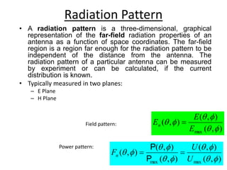
Download to read offline

![Isotropic antenna
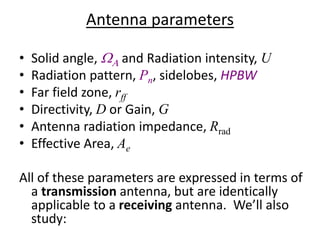
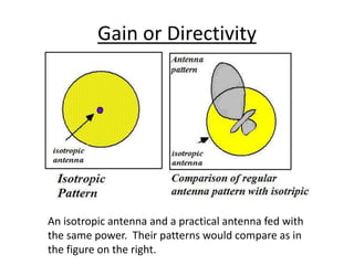
• It’s an hypothetic antenna, i.e., it does not exist in real life,
yet it’s used as a measuring bar for real antenna
characteristics.
• It’s a point source that occupies a negligible space. Has no
directional preference.
• Its pattern is simply a sphere so it has ,
beam area (WA) = Wisotropic= 4p [steradians].
p
p
p
p
4
sin
)
1
(
)
1
(
0
2
0
4
isotropic
W
W
d
d
d](https://image.slidesharecdn.com/asa-221129043044-7f30be3d/85/asa-ppt-9-320.jpg)
![Radiation Intensity
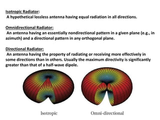
• Is the power density per solid angle:
vector.
Poynting
as
known
also
density
power
the
is
]
[W/m
ˆ
Re 2
r
2
r
H*}
{E
½
where
r
U
r
P
P [W/sr]](https://image.slidesharecdn.com/asa-221129043044-7f30be3d/85/asa-ppt-13-320.jpg)

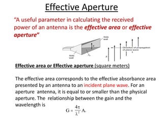
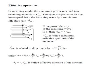
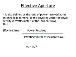
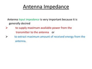


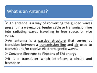
This document discusses key concepts related to wireless communication antennas. It defines important antenna parameters such as gain, directivity, effective aperture, radiation resistance, bandwidth, beamwidth, and input impedance. It also describes common antenna types including dipole antennas, folded dipoles, Yagi arrays, and parabolic reflector antennas. Finally, it discusses the history of antenna development and the roles antennas play in spatial filtering, polarization filtering, impedance transformation, and propagating electromagnetic waves.