
Recommended
More Related Content
What's hot
What's hot (20)
Similar to Analysis Report
Similar to Analysis Report (20)
Analysis Report
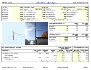
- 1. Pole ID:Pole_L-618.pplx O-Calc® Pro Analysis Report Sunday, November 6, 2016 6:49 AM User:Ocalc COMPUTER OCP:5.02 * Includes Load Factor(s) Page 1 of 4 2 Worst Wind Per Guy Wire 3 Wind At 7° Pole Num: L-618 Pole Length / Class: 35 / 6 Code: NESC Structure Type: Angle Aux Data 1 Unset Species: SOUTHERN PINE NESC Rule: Rule 250B Status: Guy Wires Adequate Aux Data 2 Unset Setting Depth (ft): 5.50 Construction Grade: C Pole Strength Factor: 0.85 Aux Data 3 Unset G/L Circumference (in): 27.17 Loading District: Heavy Transverse Wind LF: 1.75 Aux Data 4 Unset G/L Fiber Stress (psi): 8,000 Ice Thickness (in): 0.50 Wire Tension LF: 1.30 Aux Data 5 Unset Allowable Stress (psi): 6,800 Wind Speed (mph): 39.53 Vertical LF: 1.90 Aux Data 6 Unset Fiber Stress Ht. Reduc: No Wind Pressure (psf): 4.00 Latitude: 0 Deg 0 Min 0.000000 Sec N Longitude: 0 Deg 0 Min 0.000000 Sec E Elevation: 0 Feet Pole Capacity Utilization (%) Height (ft) Wind Angle (deg) Maximum 77.6 0.0 7.0 Groundline 77.6 0.0 7.0 Vertical 13.2 18.5 85.0 Pole Moments (ft-lb) Load Angle (deg) Wind Angle (deg) Max Cap Util 26,658 8.9 7.0 Groundline 26,658 8.9 7.0 GL Allowable 35,997 Guy System Component Summary Load From Worst Wind Angle on Pole Individual Maximum Load Description Lead Length (ft) Lead Angle (deg) Height (ft) Nominal Capacity (%) Wind Angle (deg) Max Load Capacity (%) Wind Angle (deg) ? Expanding - 8" - Soil Class 4 30.0 265.0 20.1 7.0 20.3 60.0 ? EHS 1/2 (Down) 23.0 18.2 7.0 20.3 60.0 ? Expanding - 8" - Soil Class 4 12.0 265.0 29.4 7.0 29.6 50.0 ? EHS 3/8 (Down) 16.3 46.7 7.0 51.6 50.0 System Capacity Summary: Adequate Adequate
- 2. Pole ID:Pole_L-618.pplx O-Calc® Pro Analysis Report Sunday, November 6, 2016 6:49 AM User:Ocalc COMPUTER OCP:5.02 * Includes Load Factor(s) Page 2 of 4 2 Worst Wind Per Guy Wire 3 Wind At 7° Groundline Load Summary - Reporting Angle Mode: Load - Reporting Angle: 8.9° Shear Load* (lbs) Applied Load (%) Bending Moment (ft-lb) Applied Moment (%) Pole Capacity (%) Bending Stress (+/- psi) Vertical Load (lbs) Vertical Stress (psi) Total Stress (psi) Pole Capacity (%) Powers 1,486 105.3 33,873 124.0 94.1 6,399 506 9 6,407 94.2 Comms 1,527 108.3 25,359 92.8 70.5 4,790 697 12 4,802 70.6 GuyBraces -1,730 -122.6 -33,718 -123.4 -93.7 -6,370 11,977 204 -6,166 -90.7 Pole 121 8.6 1,647 6.0 4.6 311 923 16 327 4.8 Crossarms 6 0.4 135 0.5 0.4 26 27 0 26 0.4 Insulators 1 0.1 30 0.1 0.1 6 25 0 6 0.1 Pole Load 1,411 100.0 27,325 100.0 75.9 5,162 14,154 241 5,403 79.5 Pole Reserve Capacity 8,672 24.1 1,638 1,397 20.5 Load Summary by Owner - Reporting Angle Mode: Load - Reporting Angle: 8.9° Shear Load* (lbs) Applied Load (%) Bending Moment (ft-lb) Applied Moment (%) Pole Capacity (%) Bending Stress (+/- psi) Vertical Load (lbs) Vertical Stress (psi) Total Stress (psi) Pole Capacity (%) DTE 666 47.2 15,019 55.0 41.7 2,837 4,621 79 2,916 42.9 CATV 717 50.8 12,531 45.9 34.8 2,367 344 6 2,373 34.9 TELCO -93 -6.6 -1,873 -6.9 -5.2 -354 8,267 141 -213 -3.1 AT&T 121 8.6 1,647 6.0 4.6 311 923 16 327 4.8 Totals: 1,411 100.0 27,325 100.0 75.9 5,162 14,154 241 5,403 79.5 Detailed Load Components: Power Owner Height (ft) Horiz. Offset (in) Cable Diameter (in) Sag at Max Temp (ft) Cable Weight (lbs/ft) Lead/Span Length (ft) Span Angle (deg) Wire Length (ft) Tension (lbs) Tension Moment* (ft-lb) Offset Moment* (ft-lb) Wind Moment* (ft-lb) Moment at GL* (ft-lb) Neutral 1/0 COPPER 7 STRAND DTE 23.42 6.25 0.3684 1.25 0.326 135.0 90.0 135.0 1,045 4,944 57 1,237 6,238 Neutral 1/0 COPPER 7 STRAND DTE 23.42 6.25 0.3684 0.40 0.326 70.0 310.0 70.0 315 4,949 30 470 5,449 Secondary 1/0 COPPER 7 STRAND DTE 22.62 6.25 0.3684 1.25 0.326 135.0 90.0 135.0 1,045 4,775 57 1,195 6,027 Secondary 1/0 COPPER 7 STRAND DTE 22.62 6.25 0.3684 0.40 0.326 70.0 310.0 70.0 315 4,780 30 454 5,264 Secondary 1/0 COPPER 7 STRAND DTE 21.82 6.25 0.3684 1.25 0.326 135.0 90.0 135.0 1,045 4,606 57 1,153 5,816 Secondary 1/0 COPPER 7 STRAND DTE 21.82 6.25 0.3684 0.40 0.326 70.0 310.0 70.0 315 4,611 30 438 5,079 Totals: 28,665 260 4,948 33,873
- 3. Pole ID:Pole_L-618.pplx O-Calc® Pro Analysis Report Sunday, November 6, 2016 6:49 AM User:Ocalc COMPUTER OCP:5.02 * Includes Load Factor(s) Page 3 of 4 2 Worst Wind Per Guy Wire 3 Wind At 7° Comm Owner Height (ft) Horiz. Offset (in) Cable Diameter (in) Sag at Max Temp (ft) Cable Weight (lbs/ft) Lead/Span Length (ft) Span Angle (deg) Wire Length (ft) Tension (lbs) Tension Moment* (ft-lb) Offset Moment* (ft-lb) Wind Moment* (ft-lb) Moment at GL* (ft-lb) Overlashed Bundle 1/4" EHS CATV 17.24 5.88 0.2500 0.66 0.121 135.0 90.0 135.0 1,800 6,269 34 1,009 7,312 CATV 3/4" CATV CATV 17.21 5.64 0.7500 0.161 135.0 90.0 135.0 35 343 377 CATV 3/4" CATV CATV 17.21 6.14 0.7500 0.161 135.0 90.0 135.0 37 343 380 Overlashed Bundle 1/4" EHS CATV 17.24 5.88 0.2500 0.18 0.121 70.0 310.0 70.0 325 3,759 17 383 4,160 CATV 3/4" CATV CATV 17.21 5.64 0.7500 0.161 70.0 310.0 70.0 18 130 148 CATV 3/4" CATV CATV 17.21 6.14 0.7500 0.161 70.0 310.0 70.0 19 130 150 Overlashed Bundle 3/8" EHS TELCO 15.62 5.97 0.3750 0.97 0.273 135.0 90.0 135.0 2,295 7,241 52 992 8,285 Telco Telco 200 Pr. TELCO 15.57 5.97 0.9400 0.480 135.0 90.0 135.0 65 387 452 Overlashed Bundle 3/8" EHS TELCO 15.62 5.97 0.3750 0.27 0.273 70.0 310.0 70.0 335 3,510 27 377 3,914 Telco Telco 200 Pr. TELCO 15.57 5.97 0.9400 0.480 70.0 310.0 70.0 34 147 181 Totals: 20,780 338 4,241 25,359 Crossarm Owner Height (ft) Horiz. Offset (in) Offset Angle (deg) Rotate Angle (deg) Unit Weight (lbs) Unit Height (in) Unit Depth (in) Unit Length (in) Offset Moment* (ft-lb) Wind Moment* (ft-lb) Moment at GL* (ft-lb) Pole Extension 3-Wire Secondary Bracket Pole Mount DTE 22.62 4.11 0.0 0.0 14.00 24.00 2.00 3.00 9 126 135 Totals: 9 126 135 Insulator Owner Height (ft) Horiz. Offset (in) Offset Angle (deg) Rotate Angle (deg) Unit Weight (lbs) Unit Diameter (in) Unit Length (in) Offset Moment* (ft-lb) Wind Moment* (ft-lb) Moment at GL* (ft-lb) Bolt CATV / 3-Bolt CATV 17.24 0.00 20.0 290.0 5.00 3.00 0.00 5 0 5 Bolt TELCO / 3-Bolt TELCO 15.62 0.00 20.0 290.0 5.00 3.00 0.00 5 0 5 Spool Spool Insulator - 20 kV DTE 23.42 4.00 0.0 0.0 1.00 2.50 2.12 1 6 7 Spool Spool Insulator - 20 kV DTE 22.62 4.00 0.0 0.0 1.00 2.50 2.12 1 6 7 Spool Spool Insulator - 20 kV DTE 21.82 4.00 0.0 0.0 1.00 2.50 2.12 1 6 7 Totals: 12 17 30 Guy Wire and Brace Owner Attach Height (ft) End Height (ft) Lead/Span Length (ft) Wire Diameter (in) Percent Solid (%) Lead Angle (deg) Incline Angle (deg) Wire Weight (lbs/ft) Rest Length (ft) Stretch Length (in) EHS 1/2 Down DTE 23.00 0.00 30.00 0.5 75.00 265.0 37.4 0.517 37.60 0.59 EHS 3/8 Down TELCO 16.29 0.00 12.00 0.375 75.00 265.0 53.5 0.273 20.06 0.82
- 4. Pole ID:Pole_L-618.pplx O-Calc® Pro Analysis Report Sunday, November 6, 2016 6:49 AM User:Ocalc COMPUTER OCP:5.02 * Includes Load Factor(s) Page 4 of 4 2 Worst Wind Per Guy Wire 3 Wind At 7° Guy Wire and Brace (Loads and Reactions) Elastic Modulus (psi) Rated Tensile Strength (lbs) Guy Strength Factor Allowable Tension (lbs) Initial Tension (lbs) Loaded Tension*² (lbs) Maximum Tension² (lbs) Applied Tension³ (lbs) Vertical Load (lbs) Shear Load In Guy Dir (lbs) Shear Load At Report Angle (lbs) Moment at GL³ (ft-lb) EHS 1/2 Down 2.30e+7 26,900 0.90 24,210 700 4,914 4,467 4,418 2,682 3,511 -846 -19,009 EHS 3/8 Down 2.30e+7 15,400 0.90 13,860 700 7,158 6,508 6,474 5,201 3,856 -929 -14,709 Totals: 7,883 7,367 -1,774 -33,718 Anchor/Rod Load Summary Owner Rod Length AGL (in) Lead Length (ft) Lead Angle (deg) Strength of Assembly (lbs) Anchor/Rod Strength Factor Allowable Load (lbs) Max Load² (lbs) Load at Pole MCU³ (lbs) Max Required Capacity² (%) Expanding - 8" - Soil Class 4 DTE 0.00 30.00 265.0 22,000 1.00 22,000 4,467 4,418 20.3 Expanding - 8" - Soil Class 4 TELCO 0.00 12.00 265.0 22,000 1.00 22,000 6,508 6,474 29.6 Pole Buckling Buckling Constant Buckling Column Height* (ft) Buckling Section Height (% Buckling Col. Hgt.) Buckling Section Diameter (in) Minimum Buckling Diameter at GL (in) Diameter at Tip (in) Diameter at GL (in) Modulus of Elasticity (psi) Pole Density (pcf) Ice Density (pcf) Pole Tip Height (ft) Buckling Load Capacity at Height (lbs) Buckling Load Applied at Height (lbs) Buckling Load Factor of Safety 0.71 18.54 33.53 7.97 15.17 5.41 8.65 1.60e+6 60.00 57.00 29.50 107,229 14,154 7.58
- 6. O-Calc® Pro Schematic View Pole Identification: L-618 Report Created: 11/6/2016 File: Pole_L-618.pplx 1 - 23.4' (281.1") Neutral 90° 135' 0.368" (1/0 COPPER 7 STRAND) Neutral 310° 70' 0.368" (1/0 COPPER 7 STRAND) 2 - 23' (276") EHS 1/2 Down Guy 23.0 ft hgt, 37.5° angle 3 - 22.6' (271.5") Pole Extension 0.2ft 2in x 24in Voff=6.0 4 - 22.6' (271.5") Secondary 90° 135' 0.368" (1/0 COPPER 7 STRAND) Secondary 310° 70' 0.368" (1/0 COPPER 7 STRAND) 5 - 21.8' (261.9") Secondary 90° 135' 0.368" (1/0 COPPER 7 STRAND) Secondary 310° 70' 0.368" (1/0 COPPER 7 STRAND)
- 7. 6 - 17.2' (206.9") 1/4" EHS 90° 135' Msgr:0.250" 1/4" EHS 310° 70' Msgr:0.250" 7 - 16.3' (195.4") EHS 3/8 Down Guy 16.3 ft hgt, 53.6° angle 8 - 15.6' (187.5") 3/8" EHS 90° 135' Msgr:0.375" 3/8" EHS 310° 70' Msgr:0.375"
- 10. Pole ID:Pole_L-629.pplx O-Calc® Pro Analysis Report Sunday, November 6, 2016 6:49 AM User:Ocalc COMPUTER OCP:5.02 * Includes Load Factor(s) Page 1 of 3 2 Worst Wind Per Guy Wire 3 Wind At 265.6° Pole Num: L-629 Pole Length / Class: 30 / 6 Code: NESC Structure Type: Unguyed Tangent Aux Data 1 Unset Species: SOUTHERN PINE NESC Rule: Rule 250B Status: Unguyed Aux Data 2 Unset Setting Depth (ft): 5.00 Construction Grade: C Pole Strength Factor: 0.85 Aux Data 3 Unset G/L Circumference (in): 25.33 Loading District: Heavy Transverse Wind LF: 1.75 Aux Data 4 Unset G/L Fiber Stress (psi): 8,000 Ice Thickness (in): 0.50 Wire Tension LF: 1.00 Aux Data 5 Unset Allowable Stress (psi): 6,800 Wind Speed (mph): 39.53 Vertical LF: 1.90 Aux Data 6 Unset Fiber Stress Ht. Reduc: No Wind Pressure (psf): 4.00 Latitude: 0 Deg 0 Min 0.000000 Sec N Longitude: 0 Deg 0 Min 0.000000 Sec E Elevation: 0 Feet Pole Capacity Utilization (%) Height (ft) Wind Angle (deg) Maximum 78.8 0.0 265.6 Groundline 78.8 0.0 265.6 Vertical 7.2 15.1 265.6 Pole Moments (ft-lb) Load Angle (deg) Wind Angle (deg) Max Cap Util 22,895 268.7 265.6 Groundline 22,895 268.7 265.6 GL Allowable 29,171 Groundline Load Summary - Reporting Angle Mode: Load - Reporting Angle: 268.7° Shear Load* (lbs) Applied Load (%) Bending Moment (ft-lb) Applied Moment (%) Pole Capacity (%) Bending Stress (+/- psi) Vertical Load (lbs) Vertical Stress (psi) Total Stress (psi) Pole Capacity (%) Powers 895 89.9 21,505 94.6 73.7 5,013 124 2 5,015 73.8 Comms 0 0.0 7 0.0 0.0 2 314 6 8 0.1 Pole 98 9.9 1,146 5.0 3.9 267 715 14 281 4.1 Insulators 2 0.2 64 0.3 0.2 15 15 0 15 0.2 Pole Load 996 100.0 22,722 100.0 77.9 5,297 1,168 23 5,320 78.2 Pole Reserve Capacity 6,449 22.1 1,503 1,480 21.8
- 11. Pole ID:Pole_L-629.pplx O-Calc® Pro Analysis Report Sunday, November 6, 2016 6:49 AM User:Ocalc COMPUTER OCP:5.02 * Includes Load Factor(s) Page 2 of 3 2 Worst Wind Per Guy Wire 3 Wind At 265.6° Load Summary by Owner - Reporting Angle Mode: Load - Reporting Angle: 268.7° Shear Load* (lbs) Applied Load (%) Bending Moment (ft-lb) Applied Moment (%) Pole Capacity (%) Bending Stress (+/- psi) Vertical Load (lbs) Vertical Stress (psi) Total Stress (psi) Pole Capacity (%) DTE 897 90.1 21,569 94.9 73.9 5,028 130 3 5,030 74.0 TELCO 0 0.0 7 0.0 0.0 2 323 6 8 0.1 AT&T 98 9.9 1,146 5.0 3.9 267 715 14 281 4.1 Totals: 996 100.0 22,722 100.0 77.9 5,297 1,168 23 5,320 78.2 Detailed Load Components: Power Owner Height (ft) Horiz. Offset (in) Cable Diameter (in) Sag at Max Temp (ft) Cable Weight (lbs/ft) Lead/Span Length (ft) Span Angle (deg) Wire Length (ft) Tension (lbs) Tension Moment* (ft-lb) Offset Moment* (ft-lb) Wind Moment* (ft-lb) Moment at GL* (ft-lb) Secondary TRIPLEX 2/0 DTE 24.00 15.51 1.2700 1.06 0.491 82.0 270.0 82.0 895 21,474 28 2 21,505 Totals: 21,474 28 2 21,505 Comm Owner Height (ft) Horiz. Offset (in) Cable Diameter (in) Sag at Max Temp (ft) Cable Weight (lbs/ft) Lead/Span Length (ft) Span Angle (deg) Wire Length (ft) Tension (lbs) Tension Moment* (ft-lb) Offset Moment* (ft-lb) Wind Moment* (ft-lb) Moment at GL* (ft-lb) Overlashed Bundle 3/8" EHS TELCO 18.22 5.57 0.3750 0.49 0.273 95.0 90.0 95.0 2,295 -41,802 1 1 -41,800 Telco Telco 200 Pr. TELCO 18.17 5.57 0.9400 0.480 95.0 90.0 95.0 1 1 2 Overlashed Bundle 3/8" EHS TELCO 18.22 5.57 0.3750 0.37 0.273 82.0 270.0 82.0 2,295 41,802 1 1 41,804 Telco Telco 200 Pr. TELCO 18.17 5.57 0.9400 0.480 82.0 270.0 82.0 1 0 1 Totals: 0 3 4 7 Insulator Owner Height (ft) Horiz. Offset (in) Offset Angle (deg) Rotate Angle (deg) Unit Weight (lbs) Unit Diameter (in) Unit Length (in) Offset Moment* (ft-lb) Wind Moment* (ft-lb) Moment at GL* (ft-lb) Bolt TELCO / 3-Bolt TELCO 18.22 0.00 180.0 90.0 5.00 3.00 0.00 0 0 0 Deadend Deadend / Secondary DTE 24.00 0.00 270.0 270.0 3.00 3.80 12.75 7 56 64 Totals: 7 56 64 Pole Buckling Buckling Constant Buckling Column Height* (ft) Buckling Section Height (% Buckling Col. Hgt.) Buckling Section Diameter (in) Minimum Buckling Diameter at GL (in) Diameter at Tip (in) Diameter at GL (in) Modulus of Elasticity (psi) Pole Density (pcf) Ice Density (pcf) Pole Tip Height (ft) Buckling Load Capacity at Height (lbs) Buckling Load Applied at Height (lbs) Buckling Load Factor of Safety 2.00 15.10 32.98 7.54 6.80 5.41 8.07 1.60e+6 60.00 57.00 25.00 16,174 1,168 13.85
- 12. Pole ID:Pole_L-629.pplx O-Calc® Pro Analysis Report Sunday, November 6, 2016 6:49 AM User:Ocalc COMPUTER OCP:5.02 * Includes Load Factor(s) Page 3 of 3 2 Worst Wind Per Guy Wire 3 Wind At 265.6°
- 14. O-Calc® Pro Schematic View Pole Identification: L-629 Report Created: 11/6/2016 File: Pole_L-629.pplx 1 - 24' (288") Secondary 270° 82' 1.270" (TRIPLEX 2/0) 2 - 18.2' (218.6") 3/8" EHS 90° 95' Msgr:0.375" 3/8" EHS 270° 82' Msgr:0.375"
- 17. Pole ID:Pole_L-631.pplx O-Calc® Pro Analysis Report Sunday, November 6, 2016 6:50 AM User:Ocalc COMPUTER OCP:5.02 * Includes Load Factor(s) Page 1 of 3 2 Worst Wind Per Guy Wire 3 Wind At 74.1° Pole Num: L-631 Pole Length / Class: 35 / 5 Code: NESC Structure Type: Unguyed Tangent Aux Data 1 Unset Species: SOUTHERN PINE NESC Rule: Rule 250B Status: Unguyed Aux Data 2 Unset Setting Depth (ft): 5.50 Construction Grade: C Pole Strength Factor: 0.85 Aux Data 3 Unset G/L Circumference (in): 29.17 Loading District: Heavy Transverse Wind LF: 1.75 Aux Data 4 Unset G/L Fiber Stress (psi): 8,000 Ice Thickness (in): 0.50 Wire Tension LF: 1.00 Aux Data 5 Unset Allowable Stress (psi): 6,800 Wind Speed (mph): 39.53 Vertical LF: 1.90 Aux Data 6 Unset Fiber Stress Ht. Reduc: No Wind Pressure (psf): 4.00 Latitude: 0 Deg 0 Min 0.000000 Sec N Longitude: 0 Deg 0 Min 0.000000 Sec E Elevation: 0 Feet Pole Capacity Utilization (%) Height (ft) Wind Angle (deg) Maximum 79.2 0.0 74.1 Groundline 79.2 0.0 74.1 Vertical 11.0 19.0 74.1 Pole Moments (ft-lb) Load Angle (deg) Wind Angle (deg) Max Cap Util 35,081 68.2 74.1 Groundline 35,081 68.2 74.1 GL Allowable 44,545 Groundline Load Summary - Reporting Angle Mode: Load - Reporting Angle: 68.2° Shear Load* (lbs) Applied Load (%) Bending Moment (ft-lb) Applied Moment (%) Pole Capacity (%) Bending Stress (+/- psi) Vertical Load (lbs) Vertical Stress (psi) Total Stress (psi) Pole Capacity (%) Powers 1,103 80.5 30,928 88.8 69.4 4,721 327 5 4,726 69.5 Comms 103 7.5 1,979 5.7 4.4 302 306 5 307 4.5 Pole 131 9.6 1,800 5.2 4.0 275 1,094 16 291 4.3 Streetlights 28 2.1 -2 0.0 0.0 0 142 2 2 0.0 Insulators 5 0.3 133 0.4 0.3 20 21 0 21 0.3 Pole Load 1,371 100.0 34,839 100.0 78.2 5,318 1,891 28 5,346 78.6 Pole Reserve Capacity 9,706 21.8 1,482 1,454 21.4
- 18. Pole ID:Pole_L-631.pplx O-Calc® Pro Analysis Report Sunday, November 6, 2016 6:50 AM User:Ocalc COMPUTER OCP:5.02 * Includes Load Factor(s) Page 2 of 3 2 Worst Wind Per Guy Wire 3 Wind At 74.1° Load Summary by Owner - Reporting Angle Mode: Load - Reporting Angle: 68.2° Shear Load* (lbs) Applied Load (%) Bending Moment (ft-lb) Applied Moment (%) Pole Capacity (%) Bending Stress (+/- psi) Vertical Load (lbs) Vertical Stress (psi) Total Stress (psi) Pole Capacity (%) DTE 1,108 80.8 31,066 89.2 69.7 4,742 338 5 4,747 69.8 TELCO 103 7.5 1,975 5.7 4.4 302 316 5 306 4.5 AT&T 131 9.6 1,800 5.2 4.0 275 1,094 16 291 4.3 <Undefined> 28 2.1 -2 0.0 0.0 0 142 2 2 0.0 Totals: 1,371 100.0 34,839 100.0 78.2 5,318 1,891 28 5,346 78.6 Detailed Load Components: Power Owner Height (ft) Horiz. Offset (in) Cable Diameter (in) Sag at Max Temp (ft) Cable Weight (lbs/ft) Lead/Span Length (ft) Span Angle (deg) Wire Length (ft) Tension (lbs) Tension Moment* (ft-lb) Offset Moment* (ft-lb) Wind Moment* (ft-lb) Moment at GL* (ft-lb) Secondary TRIPLEX 2/0 DTE 28.00 15.86 1.2700 1.60 0.491 121.0 0.0 121.0 1,168 12,154 18 2,002 14,174 Secondary TRIPLEX 2/0 DTE 28.00 15.86 1.2700 1.19 0.491 95.0 130.0 95.0 1,168 15,450 18 1,286 16,754 Totals: 27,605 35 3,288 30,928 Comm Owner Height (ft) Horiz. Offset (in) Cable Diameter (in) Sag at Max Temp (ft) Cable Weight (lbs/ft) Lead/Span Length (ft) Span Angle (deg) Wire Length (ft) Tension (lbs) Tension Moment* (ft-lb) Offset Moment* (ft-lb) Wind Moment* (ft-lb) Moment at GL* (ft-lb) Overlashed Bundle 3/8" EHS TELCO 20.60 6.01 0.3750 0.15 0.273 52.0 180.0 52.0 2,295 -17,567 -19 459 -17,127 Telco Telco 200 Pr. TELCO 20.55 6.01 0.9400 0.480 52.0 180.0 52.0 -24 179 155 Overlashed Bundle 3/8" EHS TELCO 20.60 6.01 0.3750 0.79 0.273 121.0 0.0 121.0 2,295 17,567 -44 1,067 18,590 Telco Telco 200 Pr. TELCO 20.55 6.01 0.9400 0.480 121.0 0.0 121.0 -55 417 362 Totals: 0 -143 2,122 1,979 Streetlight Owner Height (ft) Horiz. Offset (in) Offset Angle (deg) Rotate Angle (deg) Unit Weight (lbs) Unit Height (in) Unit Depth (in) Unit Diameter (in) Unit Length (in) Offset Moment* (ft-lb) Wind Moment* (ft-lb) Moment at GL* (ft-lb) General Streetlight - 8 ft. Arm 27.87 3.11 225.0 225.0 75.00 24.00 20.00 3.00 96.00 -794 792 -2 Totals: -794 792 -2 Insulator Owner Height (ft) Horiz. Offset (in) Offset Angle (deg) Rotate Angle (deg) Unit Weight (lbs) Unit Diameter (in) Unit Length (in) Offset Moment* (ft-lb) Wind Moment* (ft-lb) Moment at GL* (ft-lb) Deadend Deadend / Secondary DTE 28.00 0.00 0.0 0.0 3.00 3.80 12.75 3 66 68 Bolt TELCO / 3-Bolt TELCO 20.60 0.00 270.0 180.0 5.00 3.00 0.00 -4 0 -4 Deadend Deadend / Secondary DTE 28.00 0.00 130.0 130.0 3.00 3.80 12.75 4 66 69 Totals: 2 131 133
- 19. Pole ID:Pole_L-631.pplx O-Calc® Pro Analysis Report Sunday, November 6, 2016 6:50 AM User:Ocalc COMPUTER OCP:5.02 * Includes Load Factor(s) Page 3 of 3 2 Worst Wind Per Guy Wire 3 Wind At 74.1° Pole Buckling Buckling Constant Buckling Column Height* (ft) Buckling Section Height (% Buckling Col. Hgt.) Buckling Section Diameter (in) Minimum Buckling Diameter at GL (in) Diameter at Tip (in) Diameter at GL (in) Modulus of Elasticity (psi) Pole Density (pcf) Ice Density (pcf) Pole Tip Height (ft) Buckling Load Capacity at Height (lbs) Buckling Load Applied at Height (lbs) Buckling Load Factor of Safety 2.00 19.05 33.38 8.59 9.67 6.05 9.29 1.60e+6 60.00 57.00 29.50 17,150 1,891 9.07
- 21. O-Calc® Pro Schematic View Pole Identification: L-631 Report Created: 11/6/2016 File: Pole_L-631.pplx 1 - 28' (336") Secondary 0° 121' 1.270" (TRIPLEX 2/0) Secondary 130° 95' 1.270" (TRIPLEX 2/0) 2 - 27.9' (334.4") Streetlight - 8 ft. Arm 8.0 ft arm 3 - 20.6' (247.2") 3/8" EHS 180° 52' Msgr:0.375" 3/8" EHS 0° 121' Msgr:0.375"
- 24. Pole ID:Pole_L-632.pplx O-Calc® Pro Analysis Report Sunday, November 6, 2016 6:50 AM User:Ocalc COMPUTER OCP:5.02 * Includes Load Factor(s) Page 1 of 5 2 Worst Wind Per Guy Wire 3 Wind At 122.7° Pole Num: L-632 Pole Length / Class: 40 / 4 Code: NESC Structure Type: Guyed Tangent Aux Data 1 Unset Species: SOUTHERN PINE NESC Rule: Rule 250B Status: Guy Wires Adequate Aux Data 2 Unset Setting Depth (ft): 6.00 Construction Grade: C Pole Strength Factor: 0.85 Aux Data 3 Unset G/L Circumference (in): 33.50 Loading District: Heavy Transverse Wind LF: 1.75 Aux Data 4 Unset G/L Fiber Stress (psi): 8,000 Ice Thickness (in): 0.50 Wire Tension LF: 1.30 Aux Data 5 Unset Allowable Stress (psi): 6,800 Wind Speed (mph): 39.53 Vertical LF: 1.90 Aux Data 6 Unset Fiber Stress Ht. Reduc: No Wind Pressure (psf): 4.00 Latitude: 0 Deg 0 Min 0.000000 Sec N Longitude: 0 Deg 0 Min 0.000000 Sec E Elevation: 0 Feet Pole Capacity Utilization (%) Height (ft) Wind Angle (deg) Maximum 48.9 25.3 122.7 Groundline 11.2 0.0 171.2 Vertical 17.5 25.4 165.6 Pole Moments (ft-lb) Load Angle (deg) Wind Angle (deg) Max Cap Util 11,105 51.9 122.7 Groundline 7,137 175.4 171.2 GL Allowable 67,455
- 25. Pole ID:Pole_L-632.pplx O-Calc® Pro Analysis Report Sunday, November 6, 2016 6:50 AM User:Ocalc COMPUTER OCP:5.02 * Includes Load Factor(s) Page 2 of 5 2 Worst Wind Per Guy Wire 3 Wind At 122.7° Guy System Component Summary Load From Worst Wind Angle on Pole Individual Maximum Load Description Lead Length (ft) Lead Angle (deg) Height (ft) Nominal Capacity (%) Wind Angle (deg) Max Load Capacity (%) Wind Angle (deg) ? Single Helix Anchor 49.0 250.0 32.4 122.7 32.5 100.0 ? EHS 1/2 (Span/Head) 25.4 26.8 122.7 29.6 100.0 ? Expanding - 8" - Soil Class 4 26.0 5.0 34.7 122.7 35.6 168.4 ? EHS 1/2 (Down) 30.9 31.5 122.7 35.6 168.4 ? Expanding - 8" - Soil Class 4 23.0 5.0 12.8 122.7 13.2 165.6 ? EHS 1/4 (Down) 19.6 47.2 122.7 53.4 165.6 ? Expanding - 8" - Soil Class 4 5.0 5.0 15.1 122.7 15.6 165.6 ? EHS 3/8 (Down) 18.0 24.0 122.7 27.2 165.6 System Capacity Summary: Adequate Adequate Groundline Load Summary - Reporting Angle Mode: Load - Reporting Angle: 175.4° Shear Load* (lbs) Applied Load (%) Bending Moment (ft-lb) Applied Moment (%) Pole Capacity (%) Bending Stress (+/- psi) Vertical Load (lbs) Vertical Stress (psi) Total Stress (psi) Pole Capacity (%) Powers 4,414 773.8 133,982 986.5 198.6 13,507 969 11 13,517 198.8 Comms 2,009 352.2 37,288 274.5 55.3 3,759 1,060 12 3,771 55.5 GuyBraces -5,990 -1050.2 -160,479 -1181.6 -237.9 -16,178 16,484 185 -15,993 -235.2 PowerEquipments 25 4.4 873 6.4 1.3 88 1,273 14 102 1.5 Pole 104 18.3 1,635 12.0 2.4 165 1,618 18 183 2.7 Crossarms 7 1.1 200 1.5 0.3 20 122 1 22 0.3 Insulators 2 0.4 83 0.6 0.1 8 61 1 9 0.1 Pole Load 570 100.0 13,582 100.0 20.1 1,369 21,587 242 1,611 23.7 Pole Reserve Capacity 53,873 79.9 5,431 5,189 76.3
- 26. Pole ID:Pole_L-632.pplx O-Calc® Pro Analysis Report Sunday, November 6, 2016 6:50 AM User:Ocalc COMPUTER OCP:5.02 * Includes Load Factor(s) Page 3 of 5 2 Worst Wind Per Guy Wire 3 Wind At 122.7° Load Summary by Owner - Reporting Angle Mode: Load - Reporting Angle: 175.4° Shear Load* (lbs) Applied Load (%) Bending Moment (ft-lb) Applied Moment (%) Pole Capacity (%) Bending Stress (+/- psi) Vertical Load (lbs) Vertical Stress (psi) Total Stress (psi) Pole Capacity (%) DTE 1,379 241.7 30,702 226.1 45.5 3,095 11,267 126 3,221 47.4 TELCO 295 51.7 5,065 37.3 7.5 511 5,580 62 573 8.4 CATV -1,207 -211.7 -23,820 -175.4 -35.3 -2,401 3,121 35 -2,366 -34.8 AT&T 104 18.3 1,635 12.0 2.4 165 1,618 18 183 2.7 Totals: 570 100.0 13,582 100.0 20.1 1,369 21,587 242 1,611 23.7 Detailed Load Components: Power Owner Height (ft) Horiz. Offset (in) Cable Diameter (in) Sag at Max Temp (ft) Cable Weight (lbs/ft) Lead/Span Length (ft) Span Angle (deg) Wire Length (ft) Tension (lbs) Tension Moment* (ft-lb) Offset Moment* (ft-lb) Wind Moment* (ft-lb) Moment at GL* (ft-lb) Neutral 1/0 COPPER 7 STRAND DTE 26.20 6.25 0.3684 1.49 0.326 150.0 90.0 150.0 1,045 2,850 5 844 3,699 Secondary 1/0 COPPER 7 STRAND DTE 25.40 6.25 0.3684 1.49 0.326 150.0 90.0 150.0 1,045 2,763 5 818 3,586 Secondary 1/0 COPPER 7 STRAND DTE 24.60 6.25 0.3684 1.49 0.326 150.0 90.0 150.0 1,045 2,676 5 792 3,473 Primary ACSR 336.4 KCM 18/1 MERLIN DTE 33.66 44.38 0.6840 1.10 0.365 150.0 90.0 150.0 2,620 9,187 579 1,335 11,101 Primary ACSR 336.4 KCM 18/1 MERLIN DTE 33.66 44.38 0.6840 0.23 0.365 49.0 250.0 49.0 2,620 30,484 189 621 31,295 Primary ACSR 336.4 KCM 18/1 MERLIN DTE 33.66 44.38 0.6840 1.10 0.365 150.0 90.0 150.0 2,620 9,187 -567 1,335 9,954 Primary ACSR 336.4 KCM 18/1 MERLIN DTE 33.66 44.38 0.6840 0.23 0.365 49.0 250.0 49.0 2,620 30,484 -185 621 30,920 Secondary TRIPLEX 2/0 DTE 26.24 6.05 1.2700 1.60 0.491 121.0 180.0 121.0 1,168 39,722 92 142 39,955 Totals: 127,351 123 6,508 133,982
- 27. Pole ID:Pole_L-632.pplx O-Calc® Pro Analysis Report Sunday, November 6, 2016 6:50 AM User:Ocalc COMPUTER OCP:5.02 * Includes Load Factor(s) Page 4 of 5 2 Worst Wind Per Guy Wire 3 Wind At 122.7° Comm Owner Height (ft) Horiz. Offset (in) Cable Diameter (in) Sag at Max Temp (ft) Cable Weight (lbs/ft) Lead/Span Length (ft) Span Angle (deg) Wire Length (ft) Tension (lbs) Tension Moment* (ft-lb) Offset Moment* (ft-lb) Wind Moment* (ft-lb) Moment at GL* (ft-lb) Overlashed Bundle 3/8" EHS TELCO 17.77 6.79 0.3750 0.80 0.273 122.0 0.0 122.0 2,295 -52,850 4 70 -52,776 Telco Telco 200 Pr. TELCO 17.72 6.79 0.9400 0.480 122.0 0.0 122.0 5 27 33 Overlashed Bundle 3/8" EHS TELCO 17.77 6.79 0.3750 0.79 0.273 121.0 180.0 121.0 2,295 52,850 4 70 52,924 Telco Telco 200 Pr. TELCO 17.72 6.79 0.9400 0.480 121.0 180.0 121.0 5 27 33 Overlashed Bundle 3/8" EHS TELCO 17.77 6.79 0.3750 0.05 0.273 49.0 250.0 49.0 2,295 14,087 2 277 14,365 Overlashed Bundle 3/8" EHS TELCO 17.77 6.79 0.3750 1.19 0.273 150.0 90.0 150.0 2,295 4,245 5 688 4,938 Telco Telco 200 Pr. TELCO 17.72 6.79 0.9400 0.480 150.0 90.0 150.0 7 269 275 Overlashed Bundle 1/4" EHS CATV 19.31 6.70 0.2500 0.81 0.121 150.0 90.0 150.0 1,800 3,617 43 689 4,349 CATV 3/4" CATV CATV 19.28 6.85 0.7500 0.161 150.0 90.0 150.0 47 234 281 CATV 3/4" CATV CATV 19.28 6.57 0.7500 0.161 150.0 90.0 150.0 46 234 279 Overlashed Bundle 1/4" EHS CATV 19.31 6.70 0.2500 0.09 0.121 49.0 250.0 49.0 1,800 12,003 14 321 12,338 CATV 3/4" CATV CATV 19.28 6.85 0.7500 0.161 49.0 250.0 49.0 15 109 124 CATV 3/4" CATV CATV 19.28 6.57 0.7500 0.161 49.0 250.0 49.0 15 109 124 Totals: 33,953 214 3,121 37,288 PowerEquipment Owner Height (ft) Horiz. Offset (in) Offset Angle (deg) Rotate Angle (deg) Unit Weight (lbs) Unit Height (in) Unit Depth (in) Unit Diameter (in) Unit Length (in) Offset Moment* (ft-lb) Wind Moment* (ft-lb) Moment at GL* (ft-lb) Transformer 1PH-50KVA DTE 29.05 17.13 90.0 90.0 670.00 37.00 -- 23.00 -- 146 727 873 Totals: 146 727 873 Crossarm Owner Height (ft) Horiz. Offset (in) Offset Angle (deg) Rotate Angle (deg) Unit Weight (lbs) Unit Height (in) Unit Depth (in) Unit Length (in) Offset Moment* (ft-lb) Wind Moment* (ft-lb) Moment at GL* (ft-lb) Pole Extension 3-Wire Secondary Bracket Pole Mount DTE 25.40 4.87 90.0 90.0 14.00 24.00 2.00 3.00 1 61 61 Normal 8'x3.5"x4.5" SP 2 Pin DTE 33.00 5.80 90.0 90.0 50.00 5.80 4.80 96.00 4 135 138 Totals: 5 195 200 Insulator Owner Height (ft) Horiz. Offset (in) Offset Angle (deg) Rotate Angle (deg) Unit Weight (lbs) Unit Diameter (in) Unit Length (in) Offset Moment* (ft-lb) Wind Moment* (ft-lb) Moment at GL* (ft-lb) Bolt TELCO / 3-Bolt TELCO 17.77 0.00 90.0 180.0 5.00 3.00 0.00 0 0 0 Bolt CATV / 3-Bolt CATV 19.31 0.00 180.0 90.0 5.00 3.00 0.00 5 0 5 Spool Spool Insulator - 20 kV DTE 26.20 4.00 90.0 0.0 1.00 2.50 2.12 0 4 4 Spool Spool Insulator - 20 kV DTE 25.40 4.00 90.0 0.0 1.00 2.50 2.12 0 4 4 Spool Spool Insulator - 20 kV DTE 24.60 4.00 90.0 0.0 1.00 2.50 2.12 0 4 4 Pin 15kV Pin Insulator DTE 33.24 44.00 172.5 0.0 8.99 6.00 5.00 63 29 92 Pin 15kV Pin Insulator DTE 33.24 -44.00 7.5 0.0 8.99 6.00 5.00 -62 29 -32 Spool Spool / Secondary DTE 26.24 0.00 180.0 90.0 1.00 2.50 2.12 1 4 5 Totals: 8 75 83
- 28. Pole ID:Pole_L-632.pplx O-Calc® Pro Analysis Report Sunday, November 6, 2016 6:50 AM User:Ocalc COMPUTER OCP:5.02 * Includes Load Factor(s) Page 5 of 5 2 Worst Wind Per Guy Wire 3 Wind At 122.7° Guy Wire and Brace Owner Attach Height (ft) End Height (ft) Lead/Span Length (ft) Wire Diameter (in) Percent Solid (%) Lead Angle (deg) Incline Angle (deg) Wire Weight (lbs/ft) Rest Length (ft) Stretch Length (in) EHS 1/2 Span/Head DTE 25.44 25.44 49.00 0.625 75.00 250.0 0.0 0.517 47.18 0.69 EHS 1/2 Down DTE 30.92 0.00 26.00 0.5 75.00 5.0 49.8 0.517 40.21 1.09 EHS 1/4 Down CATV 19.64 0.00 23.00 0.25 75.00 5.0 40.4 0.121 29.98 1.20 EHS 3/8 Down TELCO 18.03 0.00 5.00 0.375 75.00 5.0 74.2 0.273 18.62 0.39 Guy Wire and Brace (Loads and Reactions) Elastic Modulus (psi) Rated Tensile Strength (lbs) Guy Strength Factor Allowable Tension (lbs) Initial Tension (lbs) Loaded Tension*² (lbs) Maximum Tension² (lbs) Applied Tension³ (lbs) Vertical Load (lbs) Shear Load In Guy Dir (lbs) Shear Load At Report Angle (lbs) Moment at GL³ (ft-lb) EHS 1/2 Span/Head 2.30e+7 26,900 0.90 24,210 700 7,157 6,506 6,480 0 6,480 1,722 44,246 EHS 1/2 Down 2.30e+7 26,900 0.90 24,210 700 8,612 7,829 7,630 5,826 4,927 -4,859 -148,677 EHS 1/4 Down 2.30e+7 6,650 0.90 5,985 700 3,197 2,907 2,825 1,830 2,152 -2,122 -41,321 EHS 3/8 Down 2.30e+7 15,400 0.90 13,860 700 3,768 3,425 3,322 3,197 902 -889 -14,727 Totals: 10,853 14,461 -6,149 -160,479 Anchor/Rod Load Summary Owner Rod Length AGL (in) Lead Length (ft) Lead Angle (deg) Strength of Assembly (lbs) Anchor/Rod Strength Factor Allowable Load (lbs) Max Load² (lbs) Load at Pole MCU³ (lbs) Max Required Capacity² (%) Single Helix Anchor DTE 18.00 49.00 250.0 20,000 1.00 20,000 6,506 6,480 32.5 Expanding - 8" - Soil Class 4 DTE 0.00 26.00 5.0 22,000 1.00 22,000 7,829 7,630 35.6 Expanding - 8" - Soil Class 4 CATV 0.00 23.00 5.0 22,000 1.00 22,000 2,907 2,825 13.2 Expanding - 8" - Soil Class 4 TELCO 0.00 5.00 5.0 22,000 1.00 22,000 3,425 3,322 15.6 Pole Buckling Buckling Constant Buckling Column Height* (ft) Buckling Section Height (% Buckling Col. Hgt.) Buckling Section Diameter (in) Minimum Buckling Diameter at GL (in) Diameter at Tip (in) Diameter at GL (in) Modulus of Elasticity (psi) Pole Density (pcf) Ice Density (pcf) Pole Tip Height (ft) Buckling Load Capacity at Height (lbs) Buckling Load Applied at Height (lbs) Buckling Load Factor of Safety 0.71 25.36 34.17 9.65 21.89 6.69 10.67 1.60e+6 60.00 57.00 34.00 123,374 21,587 5.72
- 30. O-Calc® Pro Schematic View Pole Identification: L-632 Report Created: 11/6/2016 File: Pole_L-632.pplx 1 - 33.7' (403.9") Primary 90° 150' 0.684" (ACSR 336.4 KCM 18/1 MERLIN) Primary 250° 49' 0.684" (ACSR 336.4 KCM 18/1 MERLIN) Primary 90° 150' 0.684" (ACSR 336.4 KCM 18/1 MERLIN) Primary 250° 49' 0.684" (ACSR 336.4 KCM 18/1 MERLIN) 2 - 33' (396") Normal 8ft 4.8in x 5.8in 3 - 30.9' (371") EHS 1/2 Down Guy 30.9 ft hgt, 49.9° angle 4 - 29' (348.6") Transformer 1PH-50KVA 5 - 26.2' (314.4") Neutral 90° 150' 0.368" (1/0 COPPER 7 STRAND) Secondary 180° 121' 1.270" (TRIPLEX 2/0)
- 31. 6 - 25.4' (305.2") EHS 1/2 Span/Head Guy 25.4 ft hgt 7 - 25.4' (304.8") Pole Extension 0.2ft 2in x 24in Voff=6.0 8 - 25.4' (304.8") Secondary 90° 150' 0.368" (1/0 COPPER 7 STRAND) 9 - 24.6' (295.2") Secondary 90° 150' 0.368" (1/0 COPPER 7 STRAND) 10 - 19.6' (235.6") EHS 1/4 Down Guy 19.6 ft hgt, 40.5° angle 11 - 19.3' (231.7") 1/4" EHS 90° 150' Msgr:0.250" 1/4" EHS 250° 49' Msgr:0.250" 12 - 18' (216.4") EHS 3/8 Down Guy 18.0 ft hgt, 74.5° angle 13 - 17.8' (213.3") 3/8" EHS 0° 122' Msgr:0.375" 3/8" EHS 180° 121' Msgr:0.375" 3/8" EHS 250° 49' Msgr:0.375" 3/8" EHS 90° 150' Msgr:0.375"
- 34. Pole ID:Pole_L-699.pplx O-Calc® Pro Analysis Report Sunday, November 6, 2016 6:50 AM User:Ocalc COMPUTER OCP:5.02 * Includes Load Factor(s) Page 1 of 4 2 Worst Wind Per Guy Wire 3 Wind At 90° Pole Num: L-699 Pole Length / Class: 40 / 6 Code: NESC Structure Type: Unguyed Tangent Aux Data 1 Unset Species: SOUTHERN PINE NESC Rule: Rule 250B Status: Unguyed Aux Data 2 Unset Setting Depth (ft): 6.00 Construction Grade: C Pole Strength Factor: 0.85 Aux Data 3 Unset G/L Circumference (in): 28.50 Loading District: Heavy Transverse Wind LF: 1.75 Aux Data 4 Unset G/L Fiber Stress (psi): 8,000 Ice Thickness (in): 0.50 Wire Tension LF: 1.00 Aux Data 5 Unset Allowable Stress (psi): 6,800 Wind Speed (mph): 39.53 Vertical LF: 1.90 Aux Data 6 Unset Fiber Stress Ht. Reduc: No Wind Pressure (psf): 4.00 Latitude: 0 Deg 0 Min 0.000000 Sec N Longitude: 0 Deg 0 Min 0.000000 Sec E Elevation: 0 Feet Pole Capacity Utilization (%) Height (ft) Wind Angle (deg) Maximum 92.4 0.0 90.0 Groundline 92.4 0.0 90.0 Vertical 48.1 24.4 90.0 Pole Moments (ft-lb) Load Angle (deg) Wind Angle (deg) Max Cap Util 37,986 89.4 90.0 Groundline 37,986 89.4 90.0 GL Allowable 41,535 Groundline Load Summary - Reporting Angle Mode: Load - Reporting Angle: 89.4° Shear Load* (lbs) Applied Load (%) Bending Moment (ft-lb) Applied Moment (%) Pole Capacity (%) Bending Stress (+/- psi) Vertical Load (lbs) Vertical Stress (psi) Total Stress (psi) Pole Capacity (%) Powers 776 54.3 24,269 64.3 58.4 3,973 1,623 25 3,998 58.8 Comms 497 34.8 10,880 28.8 26.2 1,781 1,170 18 1,799 26.5 Pole 144 10.1 2,236 5.9 5.4 366 1,132 18 384 5.6 Crossarms 8 0.5 239 0.6 0.6 39 122 2 41 0.6 Insulators 4 0.3 131 0.4 0.3 22 59 1 22 0.3 Pole Load 1,428 100.0 37,755 100.0 90.9 6,181 4,106 64 6,245 91.8 Pole Reserve Capacity 3,780 9.1 619 555 8.2
- 35. Pole ID:Pole_L-699.pplx O-Calc® Pro Analysis Report Sunday, November 6, 2016 6:50 AM User:Ocalc COMPUTER OCP:5.02 * Includes Load Factor(s) Page 2 of 4 2 Worst Wind Per Guy Wire 3 Wind At 90° Load Summary by Owner - Reporting Angle Mode: Load - Reporting Angle: 89.4° Shear Load* (lbs) Applied Load (%) Bending Moment (ft-lb) Applied Moment (%) Pole Capacity (%) Bending Stress (+/- psi) Vertical Load (lbs) Vertical Stress (psi) Total Stress (psi) Pole Capacity (%) DTE 787 55.2 24,630 65.2 59.3 4,032 1,785 28 4,060 59.7 CATV 264 18.5 5,949 15.8 14.3 974 590 9 983 14.5 TELCO 232 16.3 4,940 13.1 11.9 809 599 9 818 12.0 AT&T 144 10.1 2,236 5.9 5.4 366 1,132 18 384 5.6 <Undefined> 0 0.0 0 0.0 0.0 0 0 0 0 0.0 Totals: 1,428 100.0 37,755 100.0 90.9 6,181 4,106 64 6,245 91.8 Detailed Load Components: Power Owner Height (ft) Horiz. Offset (in) Cable Diameter (in) Sag at Max Temp (ft) Cable Weight (lbs/ft) Lead/Span Length (ft) Span Angle (deg) Wire Length (ft) Tension (lbs) Tension Moment* (ft-lb) Offset Moment* (ft-lb) Wind Moment* (ft-lb) Moment at GL* (ft-lb) Primary ACSR 336.4 KCM 18/1 MERLIN DTE 33.66 44.30 0.6840 1.51 0.365 188.0 0.0 188.0 2,620 873 722 3,110 4,705 Primary ACSR 336.4 KCM 18/1 MERLIN DTE 33.66 44.30 0.6840 1.29 0.365 168.0 180.0 168.0 2,620 -873 645 2,780 2,551 Primary ACSR 336.4 KCM 18/1 MERLIN DTE 33.66 44.30 0.6840 1.51 0.365 188.0 0.0 188.0 2,620 873 -720 3,110 3,263 Primary ACSR 336.4 KCM 18/1 MERLIN DTE 33.66 44.30 0.6840 1.29 0.365 168.0 180.0 168.0 2,620 -873 -644 2,780 1,263 Neutral 1/0 COPPER 7 STRAND DTE 29.02 6.25 0.3684 2.18 0.326 188.0 0.0 188.0 1,045 300 81 2,177 2,558 Neutral 1/0 COPPER 7 STRAND DTE 29.02 6.25 0.3684 1.80 0.326 168.0 180.0 168.0 1,045 -300 72 1,946 1,718 Secondary 1/0 COPPER 7 STRAND DTE 28.22 6.25 0.3684 2.18 0.326 188.0 0.0 188.0 1,045 292 81 2,117 2,490 Secondary 1/0 COPPER 7 STRAND DTE 28.22 6.25 0.3684 1.80 0.326 168.0 180.0 168.0 1,045 -292 72 1,892 1,672 Secondary 1/0 COPPER 7 STRAND DTE 27.42 6.25 0.3684 2.18 0.326 188.0 0.0 188.0 1,045 283 81 2,057 2,421 Secondary 1/0 COPPER 7 STRAND DTE 27.42 6.25 0.3684 1.80 0.326 168.0 180.0 168.0 1,045 -283 72 1,838 1,627 Totals: 0 461 23,808 24,269
- 36. Pole ID:Pole_L-699.pplx O-Calc® Pro Analysis Report Sunday, November 6, 2016 6:50 AM User:Ocalc COMPUTER OCP:5.02 * Includes Load Factor(s) Page 3 of 4 2 Worst Wind Per Guy Wire 3 Wind At 90° Comm Owner Height (ft) Horiz. Offset (in) Cable Diameter (in) Sag at Max Temp (ft) Cable Weight (lbs/ft) Lead/Span Length (ft) Span Angle (deg) Wire Length (ft) Tension (lbs) Tension Moment* (ft-lb) Offset Moment* (ft-lb) Wind Moment* (ft-lb) Moment at GL* (ft-lb) Overlashed Bundle 1/4" EHS CATV 21.42 5.88 0.2500 1.27 0.121 188.0 0.0 188.0 1,800 381 48 1,780 2,209 CATV 3/4" CATV CATV 21.39 5.54 0.7500 0.161 188.0 0.0 188.0 48 605 653 CATV 3/4" CATV CATV 21.39 6.24 0.7500 0.161 188.0 0.0 188.0 54 605 659 Overlashed Bundle 1/4" EHS CATV 21.42 5.88 0.2500 1.02 0.121 168.0 180.0 168.0 1,800 -381 43 1,591 1,252 CATV 3/4" CATV CATV 21.39 5.54 0.7500 0.161 168.0 180.0 168.0 43 540 583 CATV 3/4" CATV CATV 21.39 6.24 0.7500 0.161 168.0 180.0 168.0 49 540 589 Overlashed Bundle 3/8" EHS TELCO 20.00 5.96 0.3750 1.64 0.273 188.0 0.0 188.0 2,295 454 72 1,775 2,301 Telco Telco 100 Pr. TELCO 19.95 5.96 0.8800 0.390 188.0 0.0 188.0 82 677 759 Overlashed Bundle 3/8" EHS TELCO 20.00 5.96 0.3750 1.32 0.273 168.0 180.0 168.0 2,295 -454 64 1,586 1,197 Telco Telco 100 Pr. TELCO 19.95 5.96 0.8800 0.390 168.0 180.0 168.0 74 605 678 Totals: 0 577 10,303 10,880 Crossarm Owner Height (ft) Horiz. Offset (in) Offset Angle (deg) Rotate Angle (deg) Unit Weight (lbs) Unit Height (in) Unit Depth (in) Unit Length (in) Offset Moment* (ft-lb) Wind Moment* (ft-lb) Moment at GL* (ft-lb) Normal 8'x3.5"x4.5" SP 2 Pin DTE 33.00 5.16 0.0 0.0 50.00 5.80 4.80 96.00 0 71 72 Pole Extension 3-Wire Secondary Bracket Pole Mount DTE 28.22 4.04 90.0 90.0 14.00 24.00 2.00 3.00 9 158 167 Totals: 9 229 239 Insulator Owner Height (ft) Horiz. Offset (in) Offset Angle (deg) Rotate Angle (deg) Unit Weight (lbs) Unit Diameter (in) Unit Length (in) Offset Moment* (ft-lb) Wind Moment* (ft-lb) Moment at GL* (ft-lb) Pin 15kV Pin Insulator DTE 33.24 44.00 83.3 0.0 8.99 6.00 5.00 63 48 111 Pin 15kV Pin Insulator DTE 33.24 -44.00 276.7 0.0 8.99 6.00 5.00 -63 48 -14 Spool Spool Insulator - 20 kV DTE 29.02 4.00 90.0 0.0 1.00 2.50 2.12 1 7 8 Spool Spool Insulator - 20 kV DTE 28.22 4.00 90.0 0.0 1.00 2.50 2.12 1 7 8 Spool Spool Insulator - 20 kV DTE 27.42 4.00 90.0 0.0 1.00 2.50 2.12 1 7 8 Bolt CATV / 3-Bolt CATV 21.42 0.00 90.0 0.0 5.00 3.00 0.00 5 0 5 Bolt TELCO / 3-Bolt TELCO 20.00 0.00 90.0 0.0 5.00 3.00 0.00 5 0 5 Totals: 12 119 131 Pole Buckling Buckling Constant Buckling Column Height* (ft) Buckling Section Height (% Buckling Col. Hgt.) Buckling Section Diameter (in) Minimum Buckling Diameter at GL (in) Diameter at Tip (in) Diameter at GL (in) Modulus of Elasticity (psi) Pole Density (pcf) Ice Density (pcf) Pole Tip Height (ft) Buckling Load Capacity at Height (lbs) Buckling Load Applied at Height (lbs) Buckling Load Factor of Safety 2.00 24.42 34.35 8.17 15.88 5.41 9.08 1.60e+6 60.00 57.00 34.00 8,538 4,106 2.08
- 37. Pole ID:Pole_L-699.pplx O-Calc® Pro Analysis Report Sunday, November 6, 2016 6:50 AM User:Ocalc COMPUTER OCP:5.02 * Includes Load Factor(s) Page 4 of 4 2 Worst Wind Per Guy Wire 3 Wind At 90° Notes Date Author Description 11/6/2016 Ocalc Note (Ocalc) Recommend upgrading L-699 to a Class 4 pole.
- 39. O-Calc® Pro Pole Notes Pole Identification: L-699 Report Created: 11/6/2016 File: Pole_L-699.pplx Description: Note: Note (Ocalc) Owner: <Undefined> Date: 11/6/2016 Author: Ocalc Recommend upgrading L-699 to a Class 4 pole.
- 40. O-Calc® Pro Schematic View Pole Identification: L-699 Report Created: 11/6/2016 File: Pole_L-699.pplx 1 - 33.7' (403.9") Primary 0° 188' 0.684" (ACSR 336.4 KCM 18/1 MERLIN) Primary 180° 168' 0.684" (ACSR 336.4 KCM 18/1 MERLIN) Primary 0° 188' 0.684" (ACSR 336.4 KCM 18/1 MERLIN) Primary 180° 168' 0.684" (ACSR 336.4 KCM 18/1 MERLIN) 2 - 33' (396") Normal 8ft 4.8in x 5.8in 3 - 29' (348.2") Neutral 0° 188' 0.368" (1/0 COPPER 7 STRAND) Neutral 180° 168' 0.368" (1/0 COPPER 7 STRAND) 4 - 28.2' (338.6") Pole Extension 0.2ft 2in x 24in Voff=6.0 5 - 28.2' (338.6") Secondary 0° 188' 0.368" (1/0 COPPER 7 STRAND) Secondary 180° 168' 0.368" (1/0 COPPER 7 STRAND)
- 41. 6 - 27.4' (329") Secondary 0° 188' 0.368" (1/0 COPPER 7 STRAND) Secondary 180° 168' 0.368" (1/0 COPPER 7 STRAND) 7 - 21.4' (257") 1/4" EHS 0° 188' Msgr:0.250" 1/4" EHS 180° 168' Msgr:0.250" 8 - 20' (240") 3/8" EHS 0° 188' Msgr:0.375" 3/8" EHS 180° 168' Msgr:0.375"
- 44. Pole ID:Pole_L-700.pplx O-Calc® Pro Analysis Report Sunday, November 6, 2016 6:50 AM User:Ocalc COMPUTER OCP:5.02 * Includes Load Factor(s) Page 1 of 3 2 Worst Wind Per Guy Wire 3 Wind At 90° Pole Num: L-700 Pole Length / Class: 40 / 5 Code: NESC Structure Type: Unguyed Tangent Aux Data 1 Unset Species: SOUTHERN PINE NESC Rule: Rule 250B Status: Unguyed Aux Data 2 Unset Setting Depth (ft): 6.00 Construction Grade: C Pole Strength Factor: 0.85 Aux Data 3 Unset G/L Circumference (in): 31.00 Loading District: Heavy Transverse Wind LF: 1.75 Aux Data 4 Unset G/L Fiber Stress (psi): 8,000 Ice Thickness (in): 0.50 Wire Tension LF: 1.00 Aux Data 5 Unset Allowable Stress (psi): 6,800 Wind Speed (mph): 39.53 Vertical LF: 1.90 Aux Data 6 Unset Fiber Stress Ht. Reduc: No Wind Pressure (psf): 4.00 Latitude: 0 Deg 0 Min 0.000000 Sec N Longitude: 0 Deg 0 Min 0.000000 Sec E Elevation: 0 Feet Pole Capacity Utilization (%) Height (ft) Wind Angle (deg) Maximum 67.3 0.0 90.0 Groundline 67.3 0.0 90.0 Vertical 31.6 23.5 90.0 Pole Moments (ft-lb) Load Angle (deg) Wind Angle (deg) Max Cap Util 35,558 89.4 90.0 Groundline 35,558 89.4 90.0 GL Allowable 53,452 Groundline Load Summary - Reporting Angle Mode: Load - Reporting Angle: 89.4° Shear Load* (lbs) Applied Load (%) Bending Moment (ft-lb) Applied Moment (%) Pole Capacity (%) Bending Stress (+/- psi) Vertical Load (lbs) Vertical Stress (psi) Total Stress (psi) Pole Capacity (%) Powers 752 53.6 23,429 66.4 43.8 2,981 1,573 21 3,001 44.1 Comms 481 34.3 9,048 25.6 16.9 1,151 1,134 15 1,166 17.1 Pole 158 11.3 2,468 7.0 4.6 314 1,364 18 332 4.9 Crossarms 8 0.6 238 0.7 0.5 30 122 2 32 0.5 Insulators 4 0.3 122 0.3 0.2 16 59 1 16 0.2 Pole Load 1,403 100.0 35,305 100.0 66.1 4,491 4,252 56 4,547 66.9 Pole Reserve Capacity 18,147 34.0 2,309 2,253 33.1
- 45. Pole ID:Pole_L-700.pplx O-Calc® Pro Analysis Report Sunday, November 6, 2016 6:50 AM User:Ocalc COMPUTER OCP:5.02 * Includes Load Factor(s) Page 2 of 3 2 Worst Wind Per Guy Wire 3 Wind At 90° Load Summary by Owner - Reporting Angle Mode: Load - Reporting Angle: 89.4° Shear Load* (lbs) Applied Load (%) Bending Moment (ft-lb) Applied Moment (%) Pole Capacity (%) Bending Stress (+/- psi) Vertical Load (lbs) Vertical Stress (psi) Total Stress (psi) Pole Capacity (%) DTE 763 54.4 23,789 67.4 44.5 3,026 1,734 23 3,049 44.8 CATV 256 18.3 5,252 14.9 9.8 668 572 7 676 9.9 TELCO 225 16.1 3,795 10.8 7.1 483 581 8 490 7.2 AT&T 158 11.3 2,468 7.0 4.6 314 1,364 18 332 4.9 Totals: 1,403 100.0 35,305 100.0 66.1 4,491 4,252 56 4,547 66.9 Detailed Load Components: Power Owner Height (ft) Horiz. Offset (in) Cable Diameter (in) Sag at Max Temp (ft) Cable Weight (lbs/ft) Lead/Span Length (ft) Span Angle (deg) Wire Length (ft) Tension (lbs) Tension Moment* (ft-lb) Offset Moment* (ft-lb) Wind Moment* (ft-lb) Moment at GL* (ft-lb) Primary ACSR 336.4 KCM 18/1 MERLIN DTE 33.66 44.34 0.6840 1.29 0.365 168.0 0.0 168.0 2,620 965 645 2,780 4,389 Primary ACSR 336.4 KCM 18/1 MERLIN DTE 33.66 44.34 0.6840 1.39 0.365 177.0 180.0 177.0 2,620 -965 680 2,928 2,644 Primary ACSR 336.4 KCM 18/1 MERLIN DTE 33.66 44.34 0.6840 1.29 0.365 168.0 0.0 168.0 2,620 965 -643 2,780 3,101 Primary ACSR 336.4 KCM 18/1 MERLIN DTE 33.66 44.34 0.6840 1.39 0.365 177.0 180.0 177.0 2,620 -965 -678 2,928 1,286 Neutral 1/0 COPPER 7 STRAND DTE 28.80 6.25 0.3684 1.80 0.326 168.0 0.0 168.0 1,045 329 72 1,931 2,332 Neutral 1/0 COPPER 7 STRAND DTE 28.80 6.25 0.3684 1.97 0.326 177.0 180.0 177.0 1,045 -329 76 2,034 1,781 Secondary 1/0 COPPER 7 STRAND DTE 28.00 6.25 0.3684 1.80 0.326 168.0 0.0 168.0 1,045 320 72 1,877 2,269 Secondary 1/0 COPPER 7 STRAND DTE 28.00 6.25 0.3684 1.97 0.326 177.0 180.0 177.0 1,045 -320 76 1,978 1,734 Secondary 1/0 COPPER 7 STRAND DTE 27.20 6.25 0.3684 1.80 0.326 168.0 0.0 168.0 1,045 311 72 1,824 2,206 Secondary 1/0 COPPER 7 STRAND DTE 27.20 6.25 0.3684 1.97 0.326 177.0 180.0 177.0 1,045 -311 76 1,921 1,687 Totals: 0 447 22,982 23,429
- 46. Pole ID:Pole_L-700.pplx O-Calc® Pro Analysis Report Sunday, November 6, 2016 6:50 AM User:Ocalc COMPUTER OCP:5.02 * Includes Load Factor(s) Page 3 of 3 2 Worst Wind Per Guy Wire 3 Wind At 90° Comm Owner Height (ft) Horiz. Offset (in) Cable Diameter (in) Sag at Max Temp (ft) Cable Weight (lbs/ft) Lead/Span Length (ft) Span Angle (deg) Wire Length (ft) Tension (lbs) Tension Moment* (ft-lb) Offset Moment* (ft-lb) Wind Moment* (ft-lb) Moment at GL* (ft-lb) Overlashed Bundle 1/4" EHS CATV 19.33 6.35 0.2500 1.02 0.121 168.0 0.0 168.0 1,800 380 46 1,435 1,862 CATV 3/4" CATV CATV 19.30 6.01 0.7500 0.161 168.0 0.0 168.0 47 487 534 CATV 3/4" CATV CATV 19.30 6.70 0.7500 0.161 168.0 0.0 168.0 52 487 540 Overlashed Bundle 1/4" EHS CATV 19.33 6.35 0.2500 1.13 0.121 177.0 180.0 177.0 1,800 -380 48 1,512 1,180 CATV 3/4" CATV CATV 19.30 6.01 0.7500 0.161 177.0 180.0 177.0 49 514 563 CATV 3/4" CATV CATV 19.30 6.70 0.7500 0.161 177.0 180.0 177.0 55 514 569 Overlashed Bundle 3/8" EHS TELCO 18.25 6.41 0.3750 1.32 0.273 168.0 0.0 168.0 2,295 458 -69 1,447 1,836 Telco Telco 100 Pr. TELCO 18.20 6.41 0.8800 0.390 168.0 0.0 168.0 -79 552 472 Overlashed Bundle 3/8" EHS TELCO 18.25 6.41 0.3750 1.46 0.273 177.0 180.0 177.0 2,295 -458 -73 1,525 994 Telco Telco 100 Pr. TELCO 18.20 6.41 0.8800 0.390 177.0 180.0 177.0 -84 581 498 Totals: 0 -8 9,055 9,048 Crossarm Owner Height (ft) Horiz. Offset (in) Offset Angle (deg) Rotate Angle (deg) Unit Weight (lbs) Unit Height (in) Unit Depth (in) Unit Length (in) Offset Moment* (ft-lb) Wind Moment* (ft-lb) Moment at GL* (ft-lb) Normal 8'x3.5"x4.5" SP 2 Pin DTE 33.00 5.48 0.0 0.0 50.00 5.80 4.80 96.00 0 71 72 Pole Extension 3-Wire Secondary Bracket Pole Mount DTE 28.00 4.39 90.0 90.0 14.00 24.00 2.00 3.00 10 157 167 Totals: 10 228 238 Insulator Owner Height (ft) Horiz. Offset (in) Offset Angle (deg) Rotate Angle (deg) Unit Weight (lbs) Unit Diameter (in) Unit Length (in) Offset Moment* (ft-lb) Wind Moment* (ft-lb) Moment at GL* (ft-lb) Pin 15kV Pin Insulator DTE 33.24 44.00 82.9 0.0 8.99 6.00 5.00 63 48 111 Pin 15kV Pin Insulator DTE 33.24 -44.00 277.1 0.0 8.99 6.00 5.00 -63 48 -14 Spool Spool Insulator - 20 kV DTE 28.80 4.00 90.0 0.0 1.00 2.50 2.12 1 7 8 Spool Spool Insulator - 20 kV DTE 28.00 4.00 90.0 0.0 1.00 2.50 2.12 1 7 8 Spool Spool Insulator - 20 kV DTE 27.20 4.00 90.0 0.0 1.00 2.50 2.12 1 7 8 Bolt CATV / 3-Bolt CATV 19.33 0.00 90.0 0.0 5.00 3.00 0.00 5 0 5 Bolt TELCO / 3-Bolt TELCO 18.25 0.00 270.0 0.0 5.00 3.00 0.00 -5 0 -5 Totals: 3 118 122 Pole Buckling Buckling Constant Buckling Column Height* (ft) Buckling Section Height (% Buckling Col. Hgt.) Buckling Section Diameter (in) Minimum Buckling Diameter at GL (in) Diameter at Tip (in) Diameter at GL (in) Modulus of Elasticity (psi) Pole Density (pcf) Ice Density (pcf) Pole Tip Height (ft) Buckling Load Capacity at Height (lbs) Buckling Load Applied at Height (lbs) Buckling Load Factor of Safety 2.00 23.46 34.01 8.97 15.88 6.05 9.87 1.60e+6 60.00 57.00 34.00 13,466 4,252 3.17
- 48. O-Calc® Pro Schematic View Pole Identification: L-700 Report Created: 11/6/2016 File: Pole_L-700.pplx 1 - 33.7' (403.9") Primary 0° 168' 0.684" (ACSR 336.4 KCM 18/1 MERLIN) Primary 180° 177' 0.684" (ACSR 336.4 KCM 18/1 MERLIN) Primary 0° 168' 0.684" (ACSR 336.4 KCM 18/1 MERLIN) Primary 180° 177' 0.684" (ACSR 336.4 KCM 18/1 MERLIN) 2 - 33' (396") Normal 8ft 4.8in x 5.8in 3 - 28.8' (345.6") Neutral 0° 168' 0.368" (1/0 COPPER 7 STRAND) Neutral 180° 177' 0.368" (1/0 COPPER 7 STRAND) 4 - 28' (336") Pole Extension 0.2ft 2in x 24in Voff=6.0 5 - 28' (336") Secondary 0° 168' 0.368" (1/0 COPPER 7 STRAND) Secondary 180° 177' 0.368" (1/0 COPPER 7 STRAND)
- 49. 6 - 27.2' (326.4") Secondary 0° 168' 0.368" (1/0 COPPER 7 STRAND) Secondary 180° 177' 0.368" (1/0 COPPER 7 STRAND) 7 - 19.3' (232") 1/4" EHS 0° 168' Msgr:0.250" 1/4" EHS 180° 177' Msgr:0.250" 8 - 18.2' (219") 3/8" EHS 0° 168' Msgr:0.375" 3/8" EHS 180° 177' Msgr:0.375"
- 52. Pole ID:Pole_L-701.pplx O-Calc® Pro Analysis Report Sunday, November 6, 2016 6:50 AM User:Ocalc COMPUTER OCP:5.02 * Includes Load Factor(s) Page 1 of 5 2 Worst Wind Per Guy Wire 3 Wind At 90° Pole Num: L-701 Pole Length / Class: 40 / 5 Code: NESC Structure Type: Guyed Tangent Aux Data 1 Unset Species: SOUTHERN PINE NESC Rule: Rule 250B Status: Guy Wires Adequate Aux Data 2 Unset Setting Depth (ft): 6.00 Construction Grade: C Pole Strength Factor: 0.85 Aux Data 3 Unset G/L Circumference (in): 31.00 Loading District: Heavy Transverse Wind LF: 1.75 Aux Data 4 Unset G/L Fiber Stress (psi): 8,000 Ice Thickness (in): 0.50 Wire Tension LF: 1.30 Aux Data 5 Unset Allowable Stress (psi): 6,800 Wind Speed (mph): 39.53 Vertical LF: 1.90 Aux Data 6 Unset Fiber Stress Ht. Reduc: No Wind Pressure (psf): 4.00 Latitude: 0 Deg 0 Min 0.000000 Sec N Longitude: 0 Deg 0 Min 0.000000 Sec E Elevation: 0 Feet Pole Capacity Utilization (%) Height (ft) Wind Angle (deg) Maximum 60.3 0.0 90.0 Groundline 60.3 0.0 90.0 Vertical 5.1 24.0 0.0 Pole Moments (ft-lb) Load Angle (deg) Wind Angle (deg) Max Cap Util 31,673 99.9 90.0 Groundline 31,673 99.9 90.0 GL Allowable 53,452 Guy System Component Summary Load From Worst Wind Angle on Pole Individual Maximum Load Description Lead Length (ft) Lead Angle (deg) Height (ft) Nominal Capacity (%) Wind Angle (deg) Max Load Capacity (%) Wind Angle (deg) ? Single Helix Anchor 145.0 180.0 36.4 90.0 37.4 0.0 ? EHS 1/2 (Span/Head) 32.0 30.1 90.0 34.0 0.0 System Capacity Summary: Adequate Adequate
- 53. Pole ID:Pole_L-701.pplx O-Calc® Pro Analysis Report Sunday, November 6, 2016 6:50 AM User:Ocalc COMPUTER OCP:5.02 * Includes Load Factor(s) Page 2 of 5 2 Worst Wind Per Guy Wire 3 Wind At 90° Groundline Load Summary - Reporting Angle Mode: Load - Reporting Angle: 99.9° Shear Load* (lbs) Applied Load (%) Bending Moment (ft-lb) Applied Moment (%) Pole Capacity (%) Bending Stress (+/- psi) Vertical Load (lbs) Vertical Stress (psi) Total Stress (psi) Pole Capacity (%) Powers -615 -45.3 -22,551 -71.3 -42.2 -2,869 1,165 15 -2,854 -42.0 Comms 443 32.6 8,187 25.9 15.3 1,042 1,058 14 1,055 15.5 GuyBraces 1,315 96.8 42,084 133.1 78.7 5,354 88 1 5,355 78.7 PowerEquipments 41 3.0 873 2.8 1.6 111 1,273 17 128 1.9 Pole 156 11.4 2,432 7.7 4.6 309 1,364 18 327 4.8 Crossarms 10 0.7 294 0.9 0.6 37 217 3 40 0.6 Insulators 9 0.7 290 0.9 0.5 37 59 1 38 0.6 Pole Load 1,358 100.0 31,610 100.0 59.1 4,021 5,224 68 4,090 60.1 Pole Reserve Capacity 21,842 40.9 2,779 2,710 39.9 Load Summary by Owner - Reporting Angle Mode: Load - Reporting Angle: 99.9° Shear Load* (lbs) Applied Load (%) Bending Moment (ft-lb) Applied Moment (%) Pole Capacity (%) Bending Stress (+/- psi) Vertical Load (lbs) Vertical Stress (psi) Total Stress (psi) Pole Capacity (%) DTE 760 56.0 20,991 66.4 39.3 2,670 2,782 36 2,707 39.8 CATV 236 17.3 4,772 15.1 8.9 607 534 7 614 9.0 TELCO 207 15.2 3,415 10.8 6.4 435 543 7 442 6.5 AT&T 156 11.4 2,432 7.7 4.6 309 1,364 18 327 4.8 Totals: 1,358 100.0 31,610 100.0 59.1 4,021 5,224 68 4,090 60.1
- 54. Pole ID:Pole_L-701.pplx O-Calc® Pro Analysis Report Sunday, November 6, 2016 6:50 AM User:Ocalc COMPUTER OCP:5.02 * Includes Load Factor(s) Page 3 of 5 2 Worst Wind Per Guy Wire 3 Wind At 90° Detailed Load Components: Power Owner Height (ft) Horiz. Offset (in) Cable Diameter (in) Sag at Max Temp (ft) Cable Weight (lbs/ft) Lead/Span Length (ft) Span Angle (deg) Wire Length (ft) Tension (lbs) Tension Moment* (ft-lb) Offset Moment* (ft-lb) Wind Moment* (ft-lb) Moment at GL* (ft-lb) Neutral 1/0 COPPER 7 STRAND DTE 26.80 6.25 0.3684 1.97 0.326 177.0 0.0 177.0 1,045 -6,232 75 1,865 -4,292 Neutral 1/0 COPPER 7 STRAND DTE 26.80 6.25 0.3684 1.41 0.326 145.0 180.0 145.0 1,045 6,232 61 1,528 7,821 Secondary 1/0 COPPER 7 STRAND DTE 26.00 6.25 0.3684 1.97 0.326 177.0 0.0 177.0 1,045 -6,046 75 1,810 -4,161 Secondary 1/0 COPPER 7 STRAND DTE 26.00 6.25 0.3684 1.41 0.326 145.0 180.0 145.0 1,045 6,046 61 1,482 7,589 Secondary 1/0 COPPER 7 STRAND DTE 25.20 6.25 0.3684 1.97 0.326 177.0 0.0 177.0 1,045 -5,860 75 1,754 -4,031 Secondary 1/0 COPPER 7 STRAND DTE 25.20 6.25 0.3684 1.41 0.326 145.0 180.0 145.0 1,045 5,860 61 1,437 7,358 Primary ACSR 336.4 KCM 18/1 MERLIN DTE 33.00 56.52 0.6840 1.39 0.365 177.0 0.0 177.0 2,620 -19,239 -42 2,827 -16,454 Primary ACSR 336.4 KCM 18/1 MERLIN DTE 33.00 56.52 0.6840 1.39 0.365 177.0 0.0 177.0 2,620 -19,239 31 2,827 -16,381 Totals: -38,477 398 15,529 -22,551 Comm Owner Height (ft) Horiz. Offset (in) Cable Diameter (in) Sag at Max Temp (ft) Cable Weight (lbs/ft) Lead/Span Length (ft) Span Angle (deg) Wire Length (ft) Tension (lbs) Tension Moment* (ft-lb) Offset Moment* (ft-lb) Wind Moment* (ft-lb) Moment at GL* (ft-lb) Overlashed Bundle 1/4" EHS CATV 19.08 6.36 0.2500 1.13 0.121 177.0 0.0 177.0 1,800 -7,642 48 1,471 -6,123 CATV 3/4" CATV CATV 19.05 6.02 0.7500 0.161 177.0 0.0 177.0 49 499 548 CATV 3/4" CATV CATV 19.05 6.71 0.7500 0.161 177.0 0.0 177.0 54 499 553 Overlashed Bundle 1/4" EHS CATV 19.08 6.36 0.2500 0.76 0.121 145.0 180.0 145.0 1,800 7,642 39 1,205 8,886 CATV 3/4" CATV CATV 19.05 6.02 0.7500 0.161 145.0 180.0 145.0 40 409 449 CATV 3/4" CATV CATV 19.05 6.71 0.7500 0.161 145.0 180.0 145.0 44 409 453 Overlashed Bundle 3/8" EHS TELCO 17.89 6.43 0.3750 1.46 0.273 177.0 0.0 177.0 2,295 -9,138 -72 1,473 -7,737 Telco Telco 100 Pr. TELCO 17.84 6.43 0.8800 0.390 177.0 0.0 177.0 -83 562 479 Overlashed Bundle 3/8" EHS TELCO 17.89 6.43 0.3750 0.99 0.273 145.0 180.0 145.0 2,295 9,138 -59 1,207 10,286 Telco Telco 100 Pr. TELCO 17.84 6.43 0.8800 0.390 145.0 180.0 145.0 -68 460 392 Totals: 0 -7 8,194 8,187 PowerEquipment Owner Height (ft) Horiz. Offset (in) Offset Angle (deg) Rotate Angle (deg) Unit Weight (lbs) Unit Height (in) Unit Depth (in) Unit Diameter (in) Unit Length (in) Offset Moment* (ft-lb) Wind Moment* (ft-lb) Moment at GL* (ft-lb) Transformer 1PH-50KVA DTE 28.91 16.81 0.0 0.0 670.00 37.00 -- 23.00 -- -305 1,178 873 Totals: -305 1,178 873
- 55. Pole ID:Pole_L-701.pplx O-Calc® Pro Analysis Report Sunday, November 6, 2016 6:50 AM User:Ocalc COMPUTER OCP:5.02 * Includes Load Factor(s) Page 4 of 5 2 Worst Wind Per Guy Wire 3 Wind At 90° Crossarm Owner Height (ft) Horiz. Offset (in) Offset Angle (deg) Rotate Angle (deg) Unit Weight (lbs) Unit Height (in) Unit Depth (in) Unit Length (in) Offset Moment* (ft-lb) Wind Moment* (ft-lb) Moment at GL* (ft-lb) Pole Extension 3-Wire Secondary Bracket Pole Mount DTE 26.00 4.50 90.0 90.0 14.00 24.00 2.00 3.00 10 143 153 Normal 8' x 3.5" x 4.5" SP - 2 Deadend DTE 33.00 5.48 180.0 180.0 50.00 5.80 4.80 96.00 0 141 141 Totals: 10 284 294 Insulator Owner Height (ft) Horiz. Offset (in) Offset Angle (deg) Rotate Angle (deg) Unit Weight (lbs) Unit Diameter (in) Unit Length (in) Offset Moment* (ft-lb) Wind Moment* (ft-lb) Moment at GL* (ft-lb) Spool Spool Insulator - 20 kV DTE 26.80 4.00 90.0 0.0 1.00 2.50 2.12 1 7 8 Spool Spool Insulator - 20 kV DTE 26.00 4.00 90.0 0.0 1.00 2.50 2.12 1 7 8 Spool Spool Insulator - 20 kV DTE 25.20 4.00 90.0 0.0 1.00 2.50 2.12 1 7 8 Bolt CATV / 3-Bolt CATV 19.08 0.00 90.0 0.0 5.00 3.00 0.00 5 0 5 Bolt TELCO / 3-Bolt TELCO 17.89 0.00 270.0 0.0 5.00 3.00 0.00 -5 0 -5 Deadend Deadend Insulator DTE 33.00 44.00 277.1 180.0 8.99 3.00 30.00 -70 142 72 Deadend Deadend Insulator DTE 33.00 -44.00 82.9 180.0 8.99 3.00 30.00 53 142 195 Totals: -14 304 290 Guy Wire and Brace Owner Attach Height (ft) End Height (ft) Lead/Span Length (ft) Wire Diameter (in) Percent Solid (%) Lead Angle (deg) Incline Angle (deg) Wire Weight (lbs/ft) Rest Length (ft) Stretch Length (in) EHS 1/2 Span/Head DTE 32.00 32.00 145.00 0.625 75.00 180.0 0.0 0.517 143.24 2.37 Guy Wire and Brace (Loads and Reactions) Elastic Modulus (psi) Rated Tensile Strength (lbs) Guy Strength Factor Allowable Tension (lbs) Initial Tension (lbs) Loaded Tension*² (lbs) Maximum Tension² (lbs) Applied Tension³ (lbs) Vertical Load (lbs) Shear Load In Guy Dir (lbs) Shear Load At Report Angle (lbs) Moment at GL³ (ft-lb) EHS 1/2 Span/Head 2.30e+7 26,900 0.90 24,210 700 8,230 7,482 7,287 0 7,287 1,247 42,084 Totals: 0 7,287 1,247 42,084 Anchor/Rod Load Summary Owner Rod Length AGL (in) Lead Length (ft) Lead Angle (deg) Strength of Assembly (lbs) Anchor/Rod Strength Factor Allowable Load (lbs) Max Load² (lbs) Load at Pole MCU³ (lbs) Max Required Capacity² (%) Single Helix Anchor DTE 18.00 145.00 180.0 20,000 1.00 20,000 7,482 7,287 37.4 Pole Buckling Buckling Constant Buckling Column Height* (ft) Buckling Section Height (% Buckling Col. Hgt.) Buckling Section Diameter (in) Minimum Buckling Diameter at GL (in) Diameter at Tip (in) Diameter at GL (in) Modulus of Elasticity (psi) Pole Density (pcf) Ice Density (pcf) Pole Tip Height (ft) Buckling Load Capacity at Height (lbs) Buckling Load Applied at Height (lbs) Buckling Load Factor of Safety 0.71 24.00 34.10 8.95 10.56 6.05 9.87 1.60e+6 60.00 57.00 34.00 101,883 5,224 19.50
- 56. Pole ID:Pole_L-701.pplx O-Calc® Pro Analysis Report Sunday, November 6, 2016 6:50 AM User:Ocalc COMPUTER OCP:5.02 * Includes Load Factor(s) Page 5 of 5 2 Worst Wind Per Guy Wire 3 Wind At 90°
- 58. O-Calc® Pro Schematic View Pole Identification: L-701 Report Created: 11/6/2016 File: Pole_L-701.pplx 1 - 33' (396") Normal 8ft 4.8in x 5.8in 2 - 33' (396") Primary 0° 177' 0.684" (ACSR 336.4 KCM 18/1 MERLIN) Primary 0° 177' 0.684" (ACSR 336.4 KCM 18/1 MERLIN) 3 - 32' (384") EHS 1/2 Span/Head Guy 32.0 ft hgt 4 - 28.9' (346.9") Transformer 1PH-50KVA 5 - 26.8' (321.6") Neutral 0° 177' 0.368" (1/0 COPPER 7 STRAND) Neutral 180° 145' 0.368" (1/0 COPPER 7 STRAND) 6 - 26' (312") Pole Extension 0.2ft 2in x 24in Voff=6.0
- 59. 7 - 26' (312") Secondary 0° 177' 0.368" (1/0 COPPER 7 STRAND) Secondary 180° 145' 0.368" (1/0 COPPER 7 STRAND) 8 - 25.2' (302.4") Secondary 0° 177' 0.368" (1/0 COPPER 7 STRAND) Secondary 180° 145' 0.368" (1/0 COPPER 7 STRAND) 9 - 19.1' (228.9") 1/4" EHS 0° 177' Msgr:0.250" 1/4" EHS 180° 145' Msgr:0.250" 10 - 17.9' (214.7") 3/8" EHS 0° 177' Msgr:0.375" 3/8" EHS 180° 145' Msgr:0.375"
- 62. O-Calc® Pro Group Summary Report Pole Group: 256-340_Reports_1 Report Created: 11/6/2016 Pole Structure Type Guying Status Bending Moment Capacity (lb-ft) Bending Moment at GL (lb-ft) Pole Groundline Capacity Utilization Pole Maximum Capacity Utilization Vertical Buckling Capacity Utilization L-618 Angle Guys are adequate 35996.7 26658.4 77.6% 77.6% 13.2% L-629 Unguyed Tangent Unguyed 29171.2 22895.1 78.8% 78.8% 7.2% L-631 Unguyed Tangent Unguyed 44544.6 35080.5 79.2% 79.2% 11.0% L-632 Guyed Tangent Guys are adequate 67454.7 7136.9 11.2% 48.9% 17.5% L-699 Unguyed Tangent Unguyed 41534.8 37985.6 92.4% 92.4% 48.1% L-700 Unguyed Tangent Unguyed 53451.9 35558.1 67.3% 67.3% 31.6% L-701 Guyed Tangent Guys are adequate 53451.9 31672.6 60.3% 60.3% 5.1%