Download to read offline

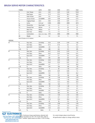

Torque Systems designs high-performance brush servo motors that provide efficiency, flexibility, and long service life. Their TORQUEMASTER 3500 series offers fast response, accurate control, and high torque-to-inertia ratios for smooth operation throughout a full speed range. It delivers superior low-speed performance and maximum power ratings for high-speed use. When integrated with brush amplifiers, the 3500 series provides effective motion control solutions for applications like factory automation.


