SlideShare a Scribd company logo
1 of 25
Download to read offline
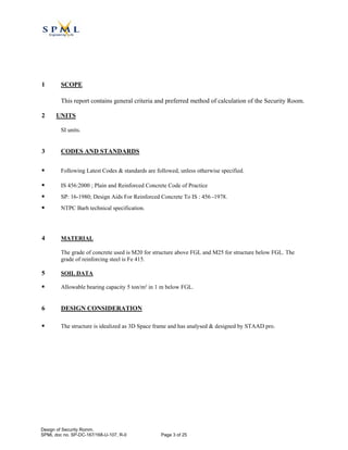
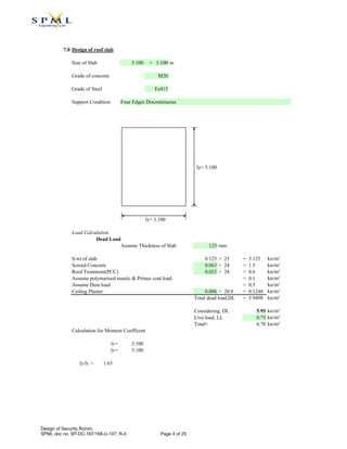
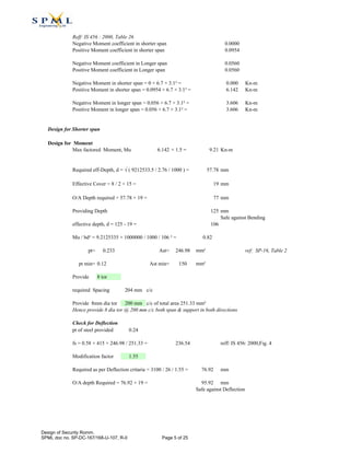
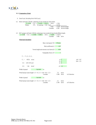
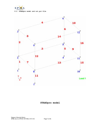
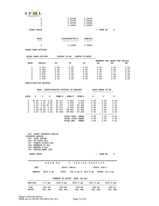
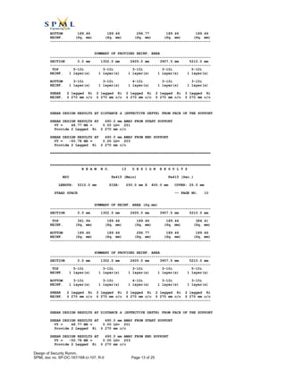
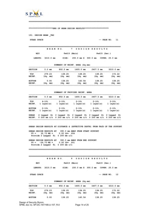
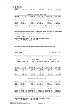
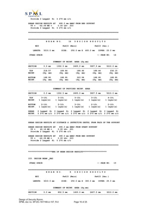
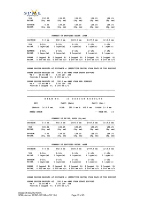
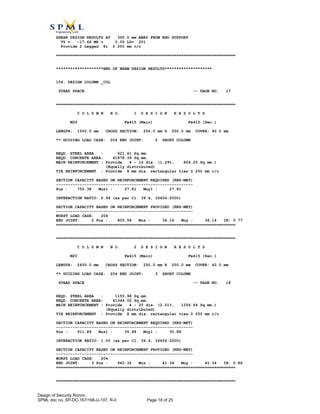
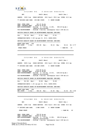
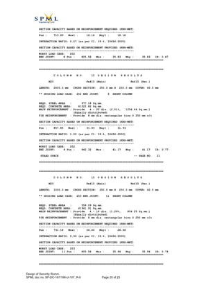
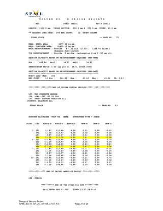
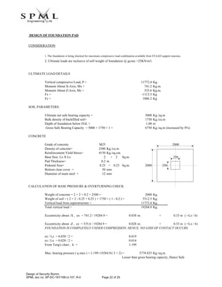
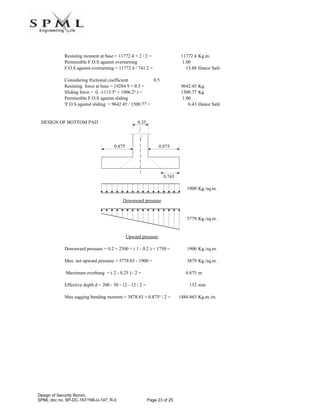
0 Submitted for approval SM/TS ACG 13.09.07
REV DESCRIPTION BY APPD DATE
SUBHASH PROJECTS AND MARKETING LTD.
113, PARK STREET
KOLKATA – 700 016
Subhash Projects and Marketing Limited
CLIENT : NTPC NATIONAL THERMAL POWER CORPORATION
LIMITED
PROJECT: ASH WATER CIRCULATION SYSTEM FOR BARH SUPER THERMAL
POWER PROJECT (3 × 660 MW)
TITLE: DESIGN OF SECURITY ROOM
NTPC NO: 9558-186-PVC- U-107 25 PAGEDOC NO:
SPML NO: SP -DC-167/168-U-107 R-0
Design of Security Romm.
SPML doc no. SP-DC-167/168-U-107, R-0 Page 1 of 25
Digitally signed by Ashok
Mittal
DN: cn=Ashok Mittal,
c=IN, o=ntpc, ou=Ntpceoc,
email=mittalashok@ntpce
oc.co.in
Reason: Cat-I (TL-60)
Date: 2007.10.29 10:53:04
+05'30'
CONTENTS
1.0 Scope 03
2.0 Units 03
3.0 Codes&Standards 03
4.0 Material 03
5.0 Soil Data 03
6.0 Design consideration 03
7.0 Design of Roof Slab. 04
8.0 Design of main structure.
8.1 Computation of loads 06
8.2 STAADpro model and out put file 07
9.0 Design of foundation 22
Design of Security Romm.
SPML doc no. SP-DC-167/168-U-107, R-0 Page 2 of 25
1 SCOPE
This report contains general criteria and preferred method of calculation of the Security Room.
2 UNITS
SI units.
3 CODES AND STANDARDS
Following Latest Codes & standards are followed, unless otherwise specified.
IS 456:2000 ; Plain and Reinforced Concrete Code of Practice
SP: 16-1980; Design Aids For Reinforced Concrete To IS : 456 -1978.
NTPC Barh technical specification.
4 MATERIAL
The grade of concrete used is M20 for structure above FGL and M25 for structure below FGL. The
grade of reinforcing steel is Fe 415.
5 SOIL DATA
Allowable bearing capacity 5 ton/m² in 1 m below FGL.
6 DESIGN CONSIDERATION
The structure is idealized as 3D Space frame and has analysed & designed by STAAD pro.
Design of Security Romm.
SPML doc no. SP-DC-167/168-U-107, R-0 Page 3 of 25
7.0 Design of roof slab
Size of Slab 5.100 × 3.100 m
Grade of concrete M20
Grade of Steel Fe415
Support Condition
ly= 5.100
lx= 3.100
Load Calculation
Dead Load
Assume Thickness of Slab 125 mm
S/wt of slab 0.125 × 25 = 3.125 kn/m²
Screed Concrete 0.063 × 24 = 1.5 kn/m²
Roof Treatment(PCC) 0.025 × 24 = 0.6 kn/m²
Assume polymarised mastic & Primer coat load = 0.1 kn/m²
Assume Dust load = 0.5 kn/m²
Ceiling Plaster 0.006 × 20.8 = 0.1248 kn/m²
Total dead load,DL = 5.9498 kn/m²
Considering, DL 5.95 kn/m²
Live load, LL 0.75 kn/m²
Total= 6.70 kn/m²
Calculation for Moment Coefficent
lx= 3.100
ly= 5.100
ly/lx = 1.65
Four Edges Discontinuous
Design of Security Romm.
SPML doc no. SP-DC-167/168-U-107, R-0 Page 4 of 25
Reff: IS 456 : 2000, Table 26
Negative Moment coefficient in shorter span 0.0000
Positive Moment coefficient in shorter span 0.0954
Negative Moment coefficient in Longer span 0.0560
Positive Moment coefficient in Longer span 0.0560
Negative Moment in shorter span = 0 × 6.7 × 3.1² = 0.000 Kn-m
Positive Moment in shorter span = 0.0954 × 6.7 × 3.1² = 6.142 Kn-m
Negative Moment in longer span = 0.056 × 6.7 × 3.1² = 3.606 Kn-m
Positive Moment in longer span = 0.056 × 6.7 × 3.1² = 3.606 Kn-m
Design for Shorter span
Design for Moment
Max factored Moment, Mu 6.142 × 1.5 = 9.21 Kn-m
Required eff-Depth, d = √ ( 9212533.5 / 2.76 / 1000 ) = 57.78 mm
Effective Cover = 8 / 2 + 15 = 19 mm
O/A Depth required = 57.78 + 19 = 77 mm
Providing Depth 125 mm
Safe against Bending
effective depth, d = 125 - 19 = 106
Mu / bd² = 9.2125335 × 1000000 / 1000 / 106 ² = 0.82
pt= 0.233 Ast= 246.98 mm² ref: SP-16, Table 2
pt min= 0.12 Ast min= 150 mm²
Provide 8 tor
required Spacing 204 mm c/c
Provide 8mm dia tor 200 mm c/c of total area 251.33 mm²
Hence provide 8 dia tor @ 200 mm c/c both span & support in both directions
Check for Deflection
pt of steel provided 0.24
fs = 0.58 × 415 × 246.98 / 251.33 = 236.54 reff: IS 456: 2000,Fig. 4
Modification factor 1.55
Required as per Deflection critaria = 3100 / 26 / 1.55 = 76.92 mm
O/A depth Required = 76.92 + 19 = 95.92 mm
Safe against Deflection
Design of Security Romm.
SPML doc no. SP-DC-167/168-U-107, R-0 Page 5 of 25
8.1.1 Computation of loads
A Dead Load, (Including Brick Wall Load )
A.1 Brick wall load ( 230 thk ), plastering 18 mm outside & 12mm Inside .
{( 0.230 × 19.2 ) + ( 0.018 + 0.012 ) × 20.8 } = 5.04
Deduct 15% for opening = 5.04 × 0.15 = 0.756
Total = 4.284 kn/m/m height
Consider 4.300 kn/m/m height
A.3 RCC parapet wall load ( 100 thk ), plastering 6 mm outside & 6mm Inside,600mm height .
{ ( 0.100 × 19.2 ) + ( 0.006 + 0.006 ) × 20.8 } × 0.600 = 1.30176
Consider 1.400 kn/m
Wind load Calculation
Basic wind speed, Vb= 47m/sec
Risk coefficient,k1= 1.07
Terrain height and structure size factor,k2= 0.98
Topography factor, k3= 1
V z = V b k 1 k 2 k 3
V z = 49.28 m/sec a= 5 a/b= 1.67
b= 3 h/b= 1.33
Pz= 1457.359 n/m² h= 4
Pz= 1.46 kn/m² cf= 1.2
Width of pannel 5 & 0.00 m
Wind load per meter height= ( 5 + 0 ) / 2 × 1.46 × 0.8 × 1.2 = 3.5 kn/m
Consider 3.500 kn/m in Z direction
Width of pannel 3 & 0.00 m
Wind load per meter height= ( 3 + 0 ) / 2 × 1.46 × 0.8 × 1.2 = 2.1 kn/m
Consider 2.100 kn/m in X direction
Design of Security Romm.
SPML doc no. SP-DC-167/168-U-107, R-0 Page 6 of 25
8.2. STAADpro model and out put file
STAADpro model
Design of Security Romm.
SPML doc no. SP-DC-167/168-U-107, R-0 Page 7 of 25
PAGE NO. 1
****************************************************
* *
* STAAD.Pro *
* Version 2006 Bld 1005.US *
* Proprietary Program of *
* Research Engineers, Intl. *
* Date= SEP 13, 2007 *
* Time= 13:37:28 *
* *
* USER ID: spml *
****************************************************
1. STAAD SPACE
INPUT FILE: design.STD
2. START JOB INFORMATION
3. ENGINEER DATE 28-AUG-07
4. END JOB INFORMATION
5. INPUT WIDTH 79
6. UNIT METER KN
7. JOINT COORDINATES
8. 1 0 0 2; 2 0 1.5 2; 3 0 4.5 2; 4 5.21 0 2; 5 5.21 1.5 2; 6 5.21 4.5 2
9. 7 0 0 5.21; 8 0 1.5 5.21; 9 0 4.5 5.21; 10 5.21 0 5.21; 11 5.21 1.5 5.21
10. 12 5.21 4.5 5.21
11. MEMBER INCIDENCES
12. 1 1 2; 2 2 3; 3 2 5; 4 3 6; 5 4 5; 6 5 6; 7 2 8; 8 3 9; 9 5 11; 10 6 12
13. 11 7 8; 12 8 9; 13 8 11; 14 9 12; 15 10 11; 16 11 12
14. START GROUP DEFINITION
15. MEMBER
16. _TB1 3 13
17. _TB2 7 9
18. _RB1 4 14
19. _RB2 8 10
20. _COL 1 2 5 6 11 12 15 16
21. END GROUP DEFINITION
22. DEFINE MATERIAL START
23. ISOTROPIC CONCRETE
24. E 2.17185E+007
25. POISSON 0.17
26. DENSITY 23.5616
27. ALPHA 1E-005
28. DAMP 0.05
29. END DEFINE MATERIAL
30. MEMBER PROPERTY INDIAN
31. _COL PRIS YD 0.25 ZD 0.25
32. _TB1 PRIS YD 0.4 ZD 0.25
33. _TB2 PRIS YD 0.3 ZD 0.25
34. _RB1 PRIS YD 0.4 ZD 0.25
35. _RB2 PRIS YD 0.3 ZD 0.25
36. CONSTANTS
37. MATERIAL CONCRETE ALL
38. SUPPORTS
39. 1 4 7 10 FIXED
40. MEMBER OFFSET
STAAD SPACE -- PAGE NO. 2
41. 2 6 12 16 END 0 -0.2 0
42. 2 6 12 16 START 0 0.2 0
43. DEFINE 1893 LOAD
44. ****ZONE-IV****
45. ZONE 0.24 RF 3 I 1.5 SS 3 ST 1 DM 0.05 DT 6
46. JOINT WEIGHT
47. 1 WEIGHT 1.657
48. 2 WEIGHT 99.895
49. 3 WEIGHT 64.499
50. 4 WEIGHT 1.657
51. 5 WEIGHT 99.895
52. 6 WEIGHT 64.499
53. 7 WEIGHT 1.657
54. 8 WEIGHT 99.895
55. 9 WEIGHT 64.499
Design of Security Romm.
SPML doc no. SP-DC-167/168-U-107, R-0 Page 8 of 25
56. 10 WEIGHT 1.657
57. 11 WEIGHT 99.895
58. 12 WEIGHT 64.499
59. LOAD 1 DEAD LOAD (DL)
NOTE : FOR SOFT STORY CHECKING WRITE "CHECK SOFT STORY" AT THE
END OF LOADING UNDER DEFINE 1893 LOAD DEFINITION.
60. SELFWEIGHT Y -1
61. MEMBER LOAD
62. 3 7 9 13 UNI GY -12.9
63. 4 8 10 14 UNI GY -1.4
64. FLOOR LOAD
65. YRANGE 4 5 FLOAD -5.95 XRANGE 0 5.5 ZRANGE 2 5.25 GY
66. LOAD 2 LIVE LOAD (LL)
67. FLOOR LOAD
68. YRANGE 4 5 FLOAD -0.75 XRANGE 0 5.5 ZRANGE 2 5.5 GY
69. LOAD 3 EARTHQUAKE LOAD IN X-DIR(EQX)
70. JOINT LOAD
71. 1 FX 11.832 FY 1.657 FZ 4.889
72. 2 FX 2.068 FY 99.895 FZ 0.204
73. 3 FX 13.9 FY 64.499 FZ -5.093
74. 4 FX 11.832 FY 1.657 FZ 4.889
75. 5 FX 2.068 FY 99.895 FZ 0.204
76. 6 FX 13.9 FY 64.499 FZ -5.093
77. 7 FX 11.832 FY 1.657 FZ -4.889
78. 8 FX 2.068 FY 99.895 FZ -0.204
79. 9 FX 13.9 FY 64.499 FZ 5.093
80. 10 FX 11.832 FY 1.657 FZ -4.889
81. 11 FX 2.068 FY 99.895 FZ -0.204
82. 12 FX 13.9 FY 64.499 FZ 5.093
83. SPECTRUM SRSS X 0.084 ACC SCALE 1 DAMP 0.05 LIN
84. 0 1; 0.03 1; 0.04 1.212; 0.05 1.406; 0.058 1.552; 0.059 1.57; 0.06 1.588
85. 0.061 1.605; 0.062 1.623; 0.065 1.675; 0.07 1.76; 0.071 1.776; 0.074 1.826
86. 0.084 1.987; 0.094 2.142; 0.104 2.292; 0.114 2.436; 0.12 2.521; 0.121 2.535
87. 0.123 2.563; 0.124 2.577; 0.126 2.604; 0.133 2.708; 0.601 2.708; 0.604 2.708
STAAD SPACE -- PAGE NO. 3
88. 0.604 2.708; 0.617 2.708; 0.622 2.708; 0.632 2.708; 0.667 2.708; 0.767 2.356
89. 0.867 2.084; 0.967 1.869; 1.067 1.694; 1.167 1.548; 1.267 1.426; 1.367 1.322
90. 1.467 1.232; 1.567 1.153; 1.667 1.084; 1.767 1.023; 1.867 0.968; 1.967 0.919
91. 2.067 0.874; 2.167 0.834; 2.267 0.797; 2.367 0.763; 2.467 0.732; 2.567 0.704
92. 2.667 0.678; 2.767 0.653; 2.867 0.63; 2.967 0.609; 3.067 0.589; 3.167 0.571
93. 3.267 0.553; 3.367 0.537; 3.467 0.521; 3.544 0.51; 3.559 0.508; 3.666 0.479
94. 3.765 0.454; 3.865 0.431; 3.965 0.409; 4.017 0.339
95. LOAD 4 EARTHQUAKE LOAD IN Z-DIR(EQZ)
96. JOINT LOAD
97. 1 FX 11.832 FY 1.657 FZ 4.889
98. 2 FX 2.068 FY 99.895 FZ 0.204
99. 3 FX 13.9 FY 64.499 FZ -5.093
100. 4 FX 11.832 FY 1.657 FZ 4.889
101. 5 FX 2.068 FY 99.895 FZ 0.204
102. 6 FX 13.9 FY 64.499 FZ -5.093
103. 7 FX 11.832 FY 1.657 FZ -4.889
104. 8 FX 2.068 FY 99.895 FZ -0.204
105. 9 FX 13.9 FY 64.499 FZ 5.093
106. 10 FX 11.832 FY 1.657 FZ -4.889
107. 11 FX 2.068 FY 99.895 FZ -0.204
108. 12 FX 13.9 FY 64.499 FZ 5.093
109. SPECTRUM SRSS Z 0.084 ACC SCALE 1 DAMP 0.05 LIN
110. 0 1; 0.03 1; 0.04 1.212; 0.05 1.406; 0.058 1.552; 0.059 1.57; 0.06 1.588
111. 0.061 1.605; 0.062 1.623; 0.065 1.675; 0.07 1.76; 0.071 1.776; 0.074 1.826
112. 0.084 1.987; 0.094 2.142; 0.104 2.292; 0.114 2.436; 0.12 2.521; 0.121 2.535
113. 0.123 2.563; 0.124 2.577; 0.126 2.604; 0.133 2.708; 0.601 2.708; 0.604 2.708
114. 0.604 2.708; 0.617 2.708; 0.622 2.708; 0.632 2.708; 0.667 2.708; 0.767 2.356
115. 0.867 2.084; 0.967 1.869; 1.067 1.694; 1.167 1.548; 1.267 1.426; 1.367 1.322
116. 1.467 1.232; 1.567 1.153; 1.667 1.084; 1.767 1.023; 1.867 0.968; 1.967 0.919
117. 2.067 0.874; 2.167 0.834; 2.267 0.797; 2.367 0.763; 2.467 0.732; 2.567 0.704
118. 2.667 0.678; 2.767 0.653; 2.867 0.63; 2.967 0.609; 3.067 0.589; 3.167 0.571
119. 3.267 0.553; 3.367 0.537; 3.467 0.521; 3.544 0.51; 3.559 0.508; 3.666 0.479
120. 3.765 0.454; 3.865 0.431; 3.965 0.409; 4.017 0.339
121. LOAD 5 WIND LOAD IN X- DIRECTION (WLX)
122. MEMBER LOAD
123. 2 12 UNI GX 2.1
124. LOAD 6 WIND LOAD IN Z- DIRECTION (WLZ)
125. MEMBER LOAD
126. 12 16 UNI GZ -3.5
Design of Security Romm.
SPML doc no. SP-DC-167/168-U-107, R-0 Page 9 of 25
127. LOAD COMB 101 (DL+LL+EQX)
128. 1 1.0 2 1.0 3 1.0
129. LOAD COMB 102 (DL+LL+EQZ)
130. 1 1.0 2 1.0 4 1.0
131. LOAD COMB 103 (DL+LL+WLX)
132. 1 1.0 2 1.0 5 1.0
133. LOAD COMB 104 (DL+LL+WLZ)
134. 1 1.0 2 1.0 6 1.0
135. LOAD COMB 201 (DL+LL+EQX)*1.5
136. 1 1.5 2 1.5 3 1.5
137. LOAD COMB 202 (DL+LL+EQZ)*1.5
138. 1 1.5 2 1.5 4 1.5
139. LOAD COMB 203 (DL+LL+WLX)*1.5
140. 1 1.5 2 1.5 5 1.5
141. LOAD COMB 204 (DL+LL+WLZ)*1.5
142. 1 1.5 2 1.5 6 1.5
143. PERFORM ANALYSIS
STAAD SPACE -- PAGE NO. 4
P R O B L E M S T A T I S T I C S
-----------------------------------
NUMBER OF JOINTS/MEMBER+ELEMENTS/SUPPORTS = 12/ 16/ 4
ORIGINAL/FINAL BAND-WIDTH= 6/ 4/ 30 DOF
TOTAL PRIMARY LOAD CASES = 6, TOTAL DEGREES OF FREEDOM = 48
SIZE OF STIFFNESS MATRIX = 2 DOUBLE KILO-WORDS
REQRD/AVAIL. DISK SPACE = 12.1/ 17176.9 MB
NUMBER OF MODES REQUESTED = 6
NUMBER OF EXISTING MASSES IN THE MODEL = 24
NUMBER OF MODES THAT WILL BE USED = 6
*** EIGENSOLUTION : SUBSPACE METHOD ***
STAAD SPACE -- PAGE NO. 5
CALCULATED FREQUENCIES FOR LOAD CASE 3
MODE FREQUENCY(CYCLES/SEC) PERIOD(SEC) ACCURACY
1 6.209 0.16104 1.046E-15
2 8.115 0.12323 8.746E-16
3 9.408 0.10629 3.904E-16
4 13.367 0.07481 5.158E-16
5 31.469 0.03178 3.722E-16
6 31.572 0.03167 5.547E-16
STAAD SPACE -- PAGE NO. 6
The following Frequencies are estimates that were calculated. These are for
information only and will not be used. Remaining values are either above
the cut off mode/freq values or are of low accuracy. To use these
frequencies, rerun with a higher cutoff mode (or mode + freq) value.
CALCULATED FREQUENCIES FOR LOAD CASE 3
MODE FREQUENCY(CYCLES/SEC) PERIOD(SEC) ACCURACY
7 31.706 0.03154 9.167E-16
8 31.849 0.03140 1.817E-16
9 54.718 0.01828 1.231E-16
10 58.381 0.01713 0.000E+00
11 67.594 0.01479 1.614E-16
12 67.643 0.01478 4.834E-16
13 67.643 0.01478 6.445E-16
14 67.716 0.01477 3.215E-16
15 122.214 0.00818 3.949E-16
16 122.361 0.00817 7.878E-16
17 170.616 0.00586 4.052E-16
18 176.409 0.00567 3.790E-16
19 222.679 0.00449 1.822E-11
20 222.794 0.00449 2.231E-11
Design of Security Romm.
SPML doc no. SP-DC-167/168-U-107, R-0 Page 10 of 25
21 320.595 0.00312 0.000E+00
22 321.205 0.00311 1.372E-15
RESPONSE LOAD CASE 3
SRSS MODAL COMBINATION METHOD USED.
DYNAMIC WEIGHT X Y Z 6.387200E+01 6.575760E+02 2.118800E+01 KN
MISSING WEIGHT X Y Z -5.359512E+00 -6.929107E+01 -5.582084E-01 KN
MODAL WEIGHT X Y Z 5.851249E+01 5.882849E+02 2.062979E+01 KN
MODE ACCELERATION-G DAMPING
---- -------------- -------
1 0.27614 0.05000
2 0.26168 0.05000
3 0.23709 0.05000
4 0.18753 0.05000
5 0.10581 0.05000
6 0.10559 0.05000
STAAD SPACE -- PAGE NO. 7
MODAL BASE ACTIONS
MODAL BASE ACTIONS FORCES IN KN LENGTH IN METE
-----------------------------------------------------------
MOMENTS ARE ABOUT THE ORIGIN
MODE PERIOD FX FY FZ MX MY MZ
1 0.161 1.36 0.00 0.00 0.00 4.89 -6.17
2 0.123 0.00 0.00 0.00 0.00 0.00 0.00
3 0.106 0.00 0.00 0.00 0.00 0.00 0.00
4 0.075 0.00 0.00 0.00 0.00 0.00 0.00
5 0.032 0.00 0.00 0.00 0.00 0.00 0.00
6 0.032 0.00 0.00 0.00 0.00 0.00 0.08
PARTICIPATION FACTORS
MASS PARTICIPATION FACTORS IN PERCENT BASE SHEAR IN KN
-------------------------------------- ------------------
MODE X Y Z SUMM-X SUMM-Y SUMM-Z X Y Z
1 91.58 0.00 0.00 91.577 0.000 0.000 1.36 0.00 0.00
2 0.00 0.00 0.00 91.577 0.000 0.000 0.00 0.00 0.00
3 0.00 0.00 97.37 91.577 0.000 97.365 0.00 0.00 0.00
4 0.00 0.00 0.00 91.577 0.000 97.365 0.00 0.00 0.00
5 0.00 89.46 0.00 91.577 89.463 97.365 0.00 0.00 0.00
6 0.03 0.00 0.00 91.609 89.463 97.365 0.00 0.00 0.00
---------------------------
TOTAL SRSS SHEAR 1.36 0.00 0.00
TOTAL 10PCT SHEAR 1.36 0.00 0.00
TOTAL ABS SHEAR 1.36 0.00 0.00
RESPONSE LOAD CASE 4
SRSS MODAL COMBINATION METHOD USED.
DYNAMIC WEIGHT X Y Z 6.387200E+01 6.575760E+02 2.118800E+01 KN
MISSING WEIGHT X Y Z -5.359512E+00 -6.929107E+01 -5.582084E-01 KN
MODAL WEIGHT X Y Z 5.851249E+01 5.882849E+02 2.062979E+01 KN
MODE ACCELERATION-G DAMPING
---- -------------- -------
1 0.27614 0.05000
Design of Security Romm.
SPML doc no. SP-DC-167/168-U-107, R-0 Page 11 of 25
2 0.26168 0.05000
3 0.23709 0.05000
4 0.18753 0.05000
5 0.10581 0.05000
STAAD SPACE -- PAGE NO. 8
MODE ACCELERATION-G DAMPING
---- -------------- -------
6 0.10559 0.05000
MODAL BASE ACTIONS
MODAL BASE ACTIONS FORCES IN KN LENGTH IN METE
-----------------------------------------------------------
MOMENTS ARE ABOUT THE ORIGIN
MODE PERIOD FX FY FZ MX MY MZ
1 0.161 0.00 0.00 0.00 0.00 0.00 0.00
2 0.123 0.00 0.00 0.00 0.00 0.00 0.00
3 0.106 0.00 0.00 0.41 1.97 -1.07 0.00
4 0.075 0.00 0.00 0.00 0.00 0.00 0.00
5 0.032 0.00 0.00 0.00 0.00 0.00 0.00
6 0.032 0.00 0.00 0.00 0.00 0.00 0.00
PARTICIPATION FACTORS
MASS PARTICIPATION FACTORS IN PERCENT BASE SHEAR IN KN
-------------------------------------- ------------------
MODE X Y Z SUMM-X SUMM-Y SUMM-Z X Y Z
1 91.58 0.00 0.00 91.577 0.000 0.000 0.00 0.00 0.00
2 0.00 0.00 0.00 91.577 0.000 0.000 0.00 0.00 0.00
3 0.00 0.00 97.37 91.577 0.000 97.365 0.00 0.00 0.41
4 0.00 0.00 0.00 91.577 0.000 97.365 0.00 0.00 0.00
5 0.00 89.46 0.00 91.577 89.463 97.365 0.00 0.00 0.00
6 0.03 0.00 0.00 91.609 89.463 97.365 0.00 0.00 0.00
---------------------------
TOTAL SRSS SHEAR 0.00 0.00 0.41
TOTAL 10PCT SHEAR 0.00 0.00 0.41
TOTAL ABS SHEAR 0.00 0.00 0.41
144. START CONCRETE DESIGN
CONCRETE DESIGN
145. CODE INDIAN
146. FC 20000 ALL
147. FYMAIN 415000 ALL
148. MAXMAIN 25 ALL
149. MAXSEC 8 ALL
150. DESIGN BEAM _TB1
STAAD SPACE -- PAGE NO. 9
============================================================================
B E A M N O. 3 D E S I G N R E S U L T S
M20 Fe415 (Main) Fe415 (Sec.)
LENGTH: 5210.0 mm SIZE: 250.0 mm X 400.0 mm COVER: 25.0 mm
SUMMARY OF REINF. AREA (Sq.mm)
----------------------------------------------------------------------------
SECTION 0.0 mm 1302.5 mm 2605.0 mm 3907.5 mm 5210.0 mm
----------------------------------------------------------------------------
TOP 341.94 189.46 189.46 189.46 384.41
REINF. (Sq. mm) (Sq. mm) (Sq. mm) (Sq. mm) (Sq. mm)
Design of Security Romm.
SPML doc no. SP-DC-167/168-U-107, R-0 Page 12 of 25
BOTTOM 189.46 189.46 296.77 189.46 189.46
REINF. (Sq. mm) (Sq. mm) (Sq. mm) (Sq. mm) (Sq. mm)
----------------------------------------------------------------------------
SUMMARY OF PROVIDED REINF. AREA
----------------------------------------------------------------------------
SECTION 0.0 mm 1302.5 mm 2605.0 mm 3907.5 mm 5210.0 mm
----------------------------------------------------------------------------
TOP 5-10í 3-10í 3-10í 3-10í 5-10í
REINF. 1 layer(s) 1 layer(s) 1 layer(s) 1 layer(s) 1 layer(s)
BOTTOM 3-10í 3-10í 4-10í 3-10í 3-10í
REINF. 1 layer(s) 1 layer(s) 1 layer(s) 1 layer(s) 1 layer(s)
SHEAR 2 legged 8í 2 legged 8í 2 legged 8í 2 legged 8í 2 legged 8í
REINF. @ 270 mm c/c @ 270 mm c/c @ 270 mm c/c @ 270 mm c/c @ 270 mm c/c
----------------------------------------------------------------------------
SHEAR DESIGN RESULTS AT DISTANCE d (EFFECTIVE DEPTH) FROM FACE OF THE SUPPORT
SHEAR DESIGN RESULTS AT 490.0 mm AWAY FROM START SUPPORT
VY = 48.77 MX = 0.00 LD= 201
Provide 2 Legged 8í @ 270 mm c/c
SHEAR DESIGN RESULTS AT 490.0 mm AWAY FROM END SUPPORT
VY = -50.78 MX = 0.00 LD= 203
Provide 2 Legged 8í @ 270 mm c/c
============================================================================
============================================================================
B E A M N O. 13 D E S I G N R E S U L T S
M20 Fe415 (Main) Fe415 (Sec.)
LENGTH: 5210.0 mm SIZE: 250.0 mm X 400.0 mm COVER: 25.0 mm
STAAD SPACE -- PAGE NO. 10
SUMMARY OF REINF. AREA (Sq.mm)
----------------------------------------------------------------------------
SECTION 0.0 mm 1302.5 mm 2605.0 mm 3907.5 mm 5210.0 mm
----------------------------------------------------------------------------
TOP 341.94 189.46 189.46 189.46 384.41
REINF. (Sq. mm) (Sq. mm) (Sq. mm) (Sq. mm) (Sq. mm)
BOTTOM 189.46 189.46 296.77 189.46 189.46
REINF. (Sq. mm) (Sq. mm) (Sq. mm) (Sq. mm) (Sq. mm)
----------------------------------------------------------------------------
SUMMARY OF PROVIDED REINF. AREA
----------------------------------------------------------------------------
SECTION 0.0 mm 1302.5 mm 2605.0 mm 3907.5 mm 5210.0 mm
----------------------------------------------------------------------------
TOP 5-10í 3-10í 3-10í 3-10í 5-10í
REINF. 1 layer(s) 1 layer(s) 1 layer(s) 1 layer(s) 1 layer(s)
BOTTOM 3-10í 3-10í 4-10í 3-10í 3-10í
REINF. 1 layer(s) 1 layer(s) 1 layer(s) 1 layer(s) 1 layer(s)
SHEAR 2 legged 8í 2 legged 8í 2 legged 8í 2 legged 8í 2 legged 8í
REINF. @ 270 mm c/c @ 270 mm c/c @ 270 mm c/c @ 270 mm c/c @ 270 mm c/c
----------------------------------------------------------------------------
SHEAR DESIGN RESULTS AT DISTANCE d (EFFECTIVE DEPTH) FROM FACE OF THE SUPPORT
SHEAR DESIGN RESULTS AT 490.0 mm AWAY FROM START SUPPORT
VY = 48.77 MX = 0.00 LD= 201
Provide 2 Legged 8í @ 270 mm c/c
SHEAR DESIGN RESULTS AT 490.0 mm AWAY FROM END SUPPORT
VY = -50.78 MX = 0.00 LD= 203
Provide 2 Legged 8í @ 270 mm c/c
Design of Security Romm.
SPML doc no. SP-DC-167/168-U-107, R-0 Page 13 of 25
============================================================================
********************END OF BEAM DESIGN RESULTS********************
151. DESIGN BEAM _TB2
STAAD SPACE -- PAGE NO. 11
============================================================================
B E A M N O. 7 D E S I G N R E S U L T S
M20 Fe415 (Main) Fe415 (Sec.)
LENGTH: 3210.0 mm SIZE: 250.0 mm X 300.0 mm COVER: 25.0 mm
SUMMARY OF REINF. AREA (Sq.mm)
----------------------------------------------------------------------------
SECTION 0.0 mm 802.5 mm 1605.0 mm 2407.5 mm 3210.0 mm
----------------------------------------------------------------------------
TOP 279.23 138.25 138.25 138.25 172.22
REINF. (Sq. mm) (Sq. mm) (Sq. mm) (Sq. mm) (Sq. mm)
BOTTOM 0.00 138.25 140.54 138.25 138.25
REINF. (Sq. mm) (Sq. mm) (Sq. mm) (Sq. mm) (Sq. mm)
----------------------------------------------------------------------------
SUMMARY OF PROVIDED REINF. AREA
----------------------------------------------------------------------------
SECTION 0.0 mm 802.5 mm 1605.0 mm 2407.5 mm 3210.0 mm
----------------------------------------------------------------------------
TOP 4-10í 2-10í 2-10í 2-10í 3-10í
REINF. 1 layer(s) 1 layer(s) 1 layer(s) 1 layer(s) 1 layer(s)
BOTTOM 2-10í 2-10í 2-10í 2-10í 2-10í
REINF. 1 layer(s) 1 layer(s) 1 layer(s) 1 layer(s) 1 layer(s)
SHEAR 2 legged 8í 2 legged 8í 2 legged 8í 2 legged 8í 2 legged 8í
REINF. @ 200 mm c/c @ 200 mm c/c @ 200 mm c/c @ 200 mm c/c @ 200 mm c/c
----------------------------------------------------------------------------
SHEAR DESIGN RESULTS AT DISTANCE d (EFFECTIVE DEPTH) FROM FACE OF THE SUPPORT
SHEAR DESIGN RESULTS AT 390.0 mm AWAY FROM START SUPPORT
VY = 32.73 MX = 0.00 LD= 204
Provide 2 Legged 8í @ 200 mm c/c
SHEAR DESIGN RESULTS AT 390.0 mm AWAY FROM END SUPPORT
VY = -26.73 MX = 0.00 LD= 201
Provide 2 Legged 8í @ 200 mm c/c
============================================================================
============================================================================
B E A M N O. 9 D E S I G N R E S U L T S
M20 Fe415 (Main) Fe415 (Sec.)
LENGTH: 3210.0 mm SIZE: 250.0 mm X 300.0 mm COVER: 25.0 mm
STAAD SPACE -- PAGE NO. 12
SUMMARY OF REINF. AREA (Sq.mm)
----------------------------------------------------------------------------
SECTION 0.0 mm 802.5 mm 1605.0 mm 2407.5 mm 3210.0 mm
----------------------------------------------------------------------------
TOP 279.23 138.25 138.25 138.25 172.22
REINF. (Sq. mm) (Sq. mm) (Sq. mm) (Sq. mm) (Sq. mm)
BOTTOM 0.00 138.25 140.54 138.25 138.25
Design of Security Romm.
SPML doc no. SP-DC-167/168-U-107, R-0 Page 14 of 25
REINF. (Sq. mm) (Sq. mm) (Sq. mm) (Sq. mm) (Sq. mm)
----------------------------------------------------------------------------
SUMMARY OF PROVIDED REINF. AREA
----------------------------------------------------------------------------
SECTION 0.0 mm 802.5 mm 1605.0 mm 2407.5 mm 3210.0 mm
----------------------------------------------------------------------------
TOP 4-10í 2-10í 2-10í 2-10í 3-10í
REINF. 1 layer(s) 1 layer(s) 1 layer(s) 1 layer(s) 1 layer(s)
BOTTOM 2-10í 2-10í 2-10í 2-10í 2-10í
REINF. 1 layer(s) 1 layer(s) 1 layer(s) 1 layer(s) 1 layer(s)
SHEAR 2 legged 8í 2 legged 8í 2 legged 8í 2 legged 8í 2 legged 8í
REINF. @ 200 mm c/c @ 200 mm c/c @ 200 mm c/c @ 200 mm c/c @ 200 mm c/c
----------------------------------------------------------------------------
SHEAR DESIGN RESULTS AT DISTANCE d (EFFECTIVE DEPTH) FROM FACE OF THE SUPPORT
SHEAR DESIGN RESULTS AT 390.0 mm AWAY FROM START SUPPORT
VY = 32.73 MX = 0.00 LD= 204
Provide 2 Legged 8í @ 200 mm c/c
SHEAR DESIGN RESULTS AT 390.0 mm AWAY FROM END SUPPORT
VY = -26.73 MX = 0.00 LD= 201
Provide 2 Legged 8í @ 200 mm c/c
============================================================================
********************END OF BEAM DESIGN RESULTS********************
152. DESIGN BEAM _RB1
STAAD SPACE -- PAGE NO. 13
============================================================================
B E A M N O. 4 D E S I G N R E S U L T S
M20 Fe415 (Main) Fe415 (Sec.)
LENGTH: 5210.0 mm SIZE: 250.0 mm X 400.0 mm COVER: 25.0 mm
SUMMARY OF REINF. AREA (Sq.mm)
----------------------------------------------------------------------------
SECTION 0.0 mm 1302.5 mm 2605.0 mm 3907.5 mm 5210.0 mm
----------------------------------------------------------------------------
TOP 218.57 189.46 189.46 189.46 236.15
REINF. (Sq. mm) (Sq. mm) (Sq. mm) (Sq. mm) (Sq. mm)
BOTTOM 188.95 188.95 323.58 188.95 188.95
REINF. (Sq. mm) (Sq. mm) (Sq. mm) (Sq. mm) (Sq. mm)
----------------------------------------------------------------------------
SUMMARY OF PROVIDED REINF. AREA
----------------------------------------------------------------------------
SECTION 0.0 mm 1302.5 mm 2605.0 mm 3907.5 mm 5210.0 mm
----------------------------------------------------------------------------
TOP 3-10í 3-10í 3-10í 3-10í 4-10í
REINF. 1 layer(s) 1 layer(s) 1 layer(s) 1 layer(s) 1 layer(s)
BOTTOM 2-12í 2-12í 3-12í 2-12í 2-12í
REINF. 1 layer(s) 1 layer(s) 1 layer(s) 1 layer(s) 1 layer(s)
SHEAR 2 legged 8í 2 legged 8í 2 legged 8í 2 legged 8í 2 legged 8í
REINF. @ 270 mm c/c @ 270 mm c/c @ 270 mm c/c @ 270 mm c/c @ 270 mm c/c
----------------------------------------------------------------------------
SHEAR DESIGN RESULTS AT DISTANCE d (EFFECTIVE DEPTH) FROM FACE OF THE SUPPORT
SHEAR DESIGN RESULTS AT 490.0 mm AWAY FROM START SUPPORT
VY = 40.16 MX = 0.00 LD= 201
Design of Security Romm.
SPML doc no. SP-DC-167/168-U-107, R-0 Page 15 of 25
Provide 2 Legged 8í @ 270 mm c/c
SHEAR DESIGN RESULTS AT 490.0 mm AWAY FROM END SUPPORT
VY = -42.09 MX = 0.00 LD= 203
Provide 2 Legged 8í @ 270 mm c/c
============================================================================
============================================================================
B E A M N O. 14 D E S I G N R E S U L T S
M20 Fe415 (Main) Fe415 (Sec.)
LENGTH: 5210.0 mm SIZE: 250.0 mm X 400.0 mm COVER: 25.0 mm
STAAD SPACE -- PAGE NO. 14
SUMMARY OF REINF. AREA (Sq.mm)
----------------------------------------------------------------------------
SECTION 0.0 mm 1302.5 mm 2605.0 mm 3907.5 mm 5210.0 mm
----------------------------------------------------------------------------
TOP 218.57 189.46 189.46 189.46 236.15
REINF. (Sq. mm) (Sq. mm) (Sq. mm) (Sq. mm) (Sq. mm)
BOTTOM 188.95 188.95 323.58 188.95 188.95
REINF. (Sq. mm) (Sq. mm) (Sq. mm) (Sq. mm) (Sq. mm)
----------------------------------------------------------------------------
SUMMARY OF PROVIDED REINF. AREA
----------------------------------------------------------------------------
SECTION 0.0 mm 1302.5 mm 2605.0 mm 3907.5 mm 5210.0 mm
----------------------------------------------------------------------------
TOP 3-10í 3-10í 3-10í 3-10í 4-10í
REINF. 1 layer(s) 1 layer(s) 1 layer(s) 1 layer(s) 1 layer(s)
BOTTOM 2-12í 2-12í 3-12í 2-12í 2-12í
REINF. 1 layer(s) 1 layer(s) 1 layer(s) 1 layer(s) 1 layer(s)
SHEAR 2 legged 8í 2 legged 8í 2 legged 8í 2 legged 8í 2 legged 8í
REINF. @ 270 mm c/c @ 270 mm c/c @ 270 mm c/c @ 270 mm c/c @ 270 mm c/c
----------------------------------------------------------------------------
SHEAR DESIGN RESULTS AT DISTANCE d (EFFECTIVE DEPTH) FROM FACE OF THE SUPPORT
SHEAR DESIGN RESULTS AT 490.0 mm AWAY FROM START SUPPORT
VY = 40.16 MX = 0.00 LD= 201
Provide 2 Legged 8í @ 270 mm c/c
SHEAR DESIGN RESULTS AT 490.0 mm AWAY FROM END SUPPORT
VY = -42.09 MX = 0.00 LD= 203
Provide 2 Legged 8í @ 270 mm c/c
============================================================================
********************END OF BEAM DESIGN RESULTS********************
153. DESIGN BEAM _RB2
STAAD SPACE -- PAGE NO. 15
============================================================================
B E A M N O. 8 D E S I G N R E S U L T S
M20 Fe415 (Main) Fe415 (Sec.)
LENGTH: 3210.0 mm SIZE: 250.0 mm X 300.0 mm COVER: 25.0 mm
SUMMARY OF REINF. AREA (Sq.mm)
----------------------------------------------------------------------------
SECTION 0.0 mm 802.5 mm 1605.0 mm 2407.5 mm 3210.0 mm
----------------------------------------------------------------------------
Design of Security Romm.
SPML doc no. SP-DC-167/168-U-107, R-0 Page 16 of 25
TOP 150.01 138.25 138.25 138.25 138.25
REINF. (Sq. mm) (Sq. mm) (Sq. mm) (Sq. mm) (Sq. mm)
BOTTOM 0.00 138.25 138.25 138.25 138.25
REINF. (Sq. mm) (Sq. mm) (Sq. mm) (Sq. mm) (Sq. mm)
----------------------------------------------------------------------------
SUMMARY OF PROVIDED REINF. AREA
----------------------------------------------------------------------------
SECTION 0.0 mm 802.5 mm 1605.0 mm 2407.5 mm 3210.0 mm
----------------------------------------------------------------------------
TOP 2-10í 2-10í 2-10í 2-10í 2-10í
REINF. 1 layer(s) 1 layer(s) 1 layer(s) 1 layer(s) 1 layer(s)
BOTTOM 2-10í 2-10í 2-10í 2-10í 2-10í
REINF. 1 layer(s) 1 layer(s) 1 layer(s) 1 layer(s) 1 layer(s)
SHEAR 2 legged 8í 2 legged 8í 2 legged 8í 2 legged 8í 2 legged 8í
REINF. @ 200 mm c/c @ 200 mm c/c @ 200 mm c/c @ 200 mm c/c @ 200 mm c/c
----------------------------------------------------------------------------
SHEAR DESIGN RESULTS AT DISTANCE d (EFFECTIVE DEPTH) FROM FACE OF THE SUPPORT
SHEAR DESIGN RESULTS AT 390.0 mm AWAY FROM START SUPPORT
VY = 20.06 MX = 0.00 LD= 204
Provide 2 Legged 8í @ 200 mm c/c
SHEAR DESIGN RESULTS AT 390.0 mm AWAY FROM END SUPPORT
VY = -17.66 MX = 0.00 LD= 201
Provide 2 Legged 8í @ 200 mm c/c
============================================================================
============================================================================
B E A M N O. 10 D E S I G N R E S U L T S
M20 Fe415 (Main) Fe415 (Sec.)
LENGTH: 3210.0 mm SIZE: 250.0 mm X 300.0 mm COVER: 25.0 mm
STAAD SPACE -- PAGE NO. 16
SUMMARY OF REINF. AREA (Sq.mm)
----------------------------------------------------------------------------
SECTION 0.0 mm 802.5 mm 1605.0 mm 2407.5 mm 3210.0 mm
----------------------------------------------------------------------------
TOP 150.01 138.25 138.25 138.25 138.25
REINF. (Sq. mm) (Sq. mm) (Sq. mm) (Sq. mm) (Sq. mm)
BOTTOM 0.00 138.25 138.25 138.25 138.25
REINF. (Sq. mm) (Sq. mm) (Sq. mm) (Sq. mm) (Sq. mm)
----------------------------------------------------------------------------
SUMMARY OF PROVIDED REINF. AREA
----------------------------------------------------------------------------
SECTION 0.0 mm 802.5 mm 1605.0 mm 2407.5 mm 3210.0 mm
----------------------------------------------------------------------------
TOP 2-10í 2-10í 2-10í 2-10í 2-10í
REINF. 1 layer(s) 1 layer(s) 1 layer(s) 1 layer(s) 1 layer(s)
BOTTOM 2-10í 2-10í 2-10í 2-10í 2-10í
REINF. 1 layer(s) 1 layer(s) 1 layer(s) 1 layer(s) 1 layer(s)
SHEAR 2 legged 8í 2 legged 8í 2 legged 8í 2 legged 8í 2 legged 8í
REINF. @ 200 mm c/c @ 200 mm c/c @ 200 mm c/c @ 200 mm c/c @ 200 mm c/c
----------------------------------------------------------------------------
SHEAR DESIGN RESULTS AT DISTANCE d (EFFECTIVE DEPTH) FROM FACE OF THE SUPPORT
SHEAR DESIGN RESULTS AT 390.0 mm AWAY FROM START SUPPORT
VY = 20.06 MX = 0.00 LD= 204
Provide 2 Legged 8í @ 200 mm c/c
Design of Security Romm.
SPML doc no. SP-DC-167/168-U-107, R-0 Page 17 of 25
SHEAR DESIGN RESULTS AT 390.0 mm AWAY FROM END SUPPORT
VY = -17.66 MX = 0.00 LD= 201
Provide 2 Legged 8í @ 200 mm c/c
============================================================================
********************END OF BEAM DESIGN RESULTS********************
154. DESIGN COLUMN _COL
STAAD SPACE -- PAGE NO. 17
============================================================================
C O L U M N N O. 1 D E S I G N R E S U L T S
M20 Fe415 (Main) Fe415 (Sec.)
LENGTH: 1500.0 mm CROSS SECTION: 250.0 mm X 250.0 mm COVER: 40.0 mm
** GUIDING LOAD CASE: 204 END JOINT: 2 SHORT COLUMN
REQD. STEEL AREA : 621.61 Sq.mm.
REQD. CONCRETE AREA: 61878.39 Sq.mm.
MAIN REINFORCEMENT : Provide 4 - 16 dia. (1.29%, 804.25 Sq.mm.)
(Equally distributed)
TIE REINFORCEMENT : Provide 8 mm dia. rectangular ties @ 250 mm c/c
SECTION CAPACITY BASED ON REINFORCEMENT REQUIRED (KNS-MET)
----------------------------------------------------------
Puz : 750.38 Muz1 : 27.81 Muy1 : 27.81
INTERACTION RATIO: 0.99 (as per Cl. 39.6, IS456:2000)
SECTION CAPACITY BASED ON REINFORCEMENT PROVIDED (KNS-MET)
----------------------------------------------------------
WORST LOAD CASE: 204
END JOINT: 2 Puz : 805.58 Muz : 36.14 Muy : 36.14 IR: 0.77
============================================================================
============================================================================
C O L U M N N O. 2 D E S I G N R E S U L T S
M20 Fe415 (Main) Fe415 (Sec.)
LENGTH: 2600.0 mm CROSS SECTION: 250.0 mm X 250.0 mm COVER: 40.0 mm
** GUIDING LOAD CASE: 204 END JOINT: 3 SHORT COLUMN
STAAD SPACE -- PAGE NO. 18
REQD. STEEL AREA : 1155.98 Sq.mm.
REQD. CONCRETE AREA: 61344.02 Sq.mm.
MAIN REINFORCEMENT : Provide 4 - 20 dia. (2.01%, 1256.64 Sq.mm.)
(Equally distributed)
TIE REINFORCEMENT : Provide 8 mm dia. rectangular ties @ 250 mm c/c
SECTION CAPACITY BASED ON REINFORCEMENT REQUIRED (KNS-MET)
----------------------------------------------------------
Puz : 911.89 Muz1 : 35.88 Muy1 : 35.88
INTERACTION RATIO: 1.00 (as per Cl. 39.6, IS456:2000)
SECTION CAPACITY BASED ON REINFORCEMENT PROVIDED (KNS-MET)
----------------------------------------------------------
WORST LOAD CASE: 204
END JOINT: 3 Puz : 942.32 Muz : 41.34 Muy : 41.34 IR: 0.86
============================================================================
============================================================================
Design of Security Romm.
SPML doc no. SP-DC-167/168-U-107, R-0 Page 18 of 25
C O L U M N N O. 5 D E S I G N R E S U L T S
M20 Fe415 (Main) Fe415 (Sec.)
LENGTH: 1500.0 mm CROSS SECTION: 250.0 mm X 250.0 mm COVER: 40.0 mm
** GUIDING LOAD CASE: 204 END JOINT: 5 SHORT COLUMN
REQD. STEEL AREA : 621.61 Sq.mm.
REQD. CONCRETE AREA: 61878.39 Sq.mm.
MAIN REINFORCEMENT : Provide 4 - 16 dia. (1.29%, 804.25 Sq.mm.)
(Equally distributed)
TIE REINFORCEMENT : Provide 8 mm dia. rectangular ties @ 250 mm c/c
SECTION CAPACITY BASED ON REINFORCEMENT REQUIRED (KNS-MET)
----------------------------------------------------------
Puz : 750.38 Muz1 : 27.81 Muy1 : 27.81
INTERACTION RATIO: 0.99 (as per Cl. 39.6, IS456:2000)
SECTION CAPACITY BASED ON REINFORCEMENT PROVIDED (KNS-MET)
----------------------------------------------------------
WORST LOAD CASE: 204
END JOINT: 5 Puz : 805.58 Muz : 36.14 Muy : 36.14 IR: 0.77
STAAD SPACE -- PAGE NO. 19
============================================================================
============================================================================
C O L U M N N O. 6 D E S I G N R E S U L T S
M20 Fe415 (Main) Fe415 (Sec.)
LENGTH: 2600.0 mm CROSS SECTION: 250.0 mm X 250.0 mm COVER: 40.0 mm
** GUIDING LOAD CASE: 204 END JOINT: 6 SHORT COLUMN
REQD. STEEL AREA : 1155.98 Sq.mm.
REQD. CONCRETE AREA: 61344.02 Sq.mm.
MAIN REINFORCEMENT : Provide 4 - 20 dia. (2.01%, 1256.64 Sq.mm.)
(Equally distributed)
TIE REINFORCEMENT : Provide 8 mm dia. rectangular ties @ 250 mm c/c
SECTION CAPACITY BASED ON REINFORCEMENT REQUIRED (KNS-MET)
----------------------------------------------------------
Puz : 911.89 Muz1 : 35.88 Muy1 : 35.88
INTERACTION RATIO: 1.00 (as per Cl. 39.6, IS456:2000)
SECTION CAPACITY BASED ON REINFORCEMENT PROVIDED (KNS-MET)
----------------------------------------------------------
WORST LOAD CASE: 204
END JOINT: 6 Puz : 942.32 Muz : 41.34 Muy : 41.34 IR: 0.86
============================================================================
============================================================================
C O L U M N N O. 11 D E S I G N R E S U L T S
M20 Fe415 (Main) Fe415 (Sec.)
LENGTH: 1500.0 mm CROSS SECTION: 250.0 mm X 250.0 mm COVER: 40.0 mm
** GUIDING LOAD CASE: 6 END JOINT: 8 SHORT COLUMN
STAAD SPACE -- PAGE NO. 20
REQD. STEEL AREA : 500.00 Sq.mm.
REQD. CONCRETE AREA: 62000.00 Sq.mm.
MAIN REINFORCEMENT : Provide 4 - 16 dia. (1.29%, 804.25 Sq.mm.)
(Equally distributed)
TIE REINFORCEMENT : Provide 8 mm dia. rectangular ties @ 250 mm c/c
Design of Security Romm.
SPML doc no. SP-DC-167/168-U-107, R-0 Page 19 of 25
SECTION CAPACITY BASED ON REINFORCEMENT REQUIRED (KNS-MET)
----------------------------------------------------------
Puz : 713.63 Muz1 : 16.16 Muy1 : 16.16
INTERACTION RATIO: 0.07 (as per Cl. 39.6, IS456:2000)
SECTION CAPACITY BASED ON REINFORCEMENT PROVIDED (KNS-MET)
----------------------------------------------------------
WORST LOAD CASE: 202
END JOINT: 8 Puz : 805.58 Muz : 35.83 Muy : 35.83 IR: 0.67
============================================================================
============================================================================
C O L U M N N O. 12 D E S I G N R E S U L T S
M20 Fe415 (Main) Fe415 (Sec.)
LENGTH: 2600.0 mm CROSS SECTION: 250.0 mm X 250.0 mm COVER: 40.0 mm
** GUIDING LOAD CASE: 202 END JOINT: 9 SHORT COLUMN
REQD. STEEL AREA : 977.18 Sq.mm.
REQD. CONCRETE AREA: 61522.82 Sq.mm.
MAIN REINFORCEMENT : Provide 4 - 20 dia. (2.01%, 1256.64 Sq.mm.)
(Equally distributed)
TIE REINFORCEMENT : Provide 8 mm dia. rectangular ties @ 250 mm c/c
SECTION CAPACITY BASED ON REINFORCEMENT REQUIRED (KNS-MET)
----------------------------------------------------------
Puz : 857.85 Muz1 : 31.93 Muy1 : 31.93
INTERACTION RATIO: 1.00 (as per Cl. 39.6, IS456:2000)
SECTION CAPACITY BASED ON REINFORCEMENT PROVIDED (KNS-MET)
----------------------------------------------------------
WORST LOAD CASE: 202
END JOINT: 9 Puz : 942.32 Muz : 41.17 Muy : 41.17 IR: 0.77
STAAD SPACE -- PAGE NO. 21
============================================================================
============================================================================
C O L U M N N O. 15 D E S I G N R E S U L T S
M20 Fe415 (Main) Fe415 (Sec.)
LENGTH: 1500.0 mm CROSS SECTION: 250.0 mm X 250.0 mm COVER: 40.0 mm
** GUIDING LOAD CASE: 203 END JOINT: 11 SHORT COLUMN
REQD. STEEL AREA : 558.09 Sq.mm.
REQD. CONCRETE AREA: 61941.91 Sq.mm.
MAIN REINFORCEMENT : Provide 4 - 16 dia. (1.29%, 804.25 Sq.mm.)
(Equally distributed)
TIE REINFORCEMENT : Provide 8 mm dia. rectangular ties @ 250 mm c/c
SECTION CAPACITY BASED ON REINFORCEMENT REQUIRED (KNS-MET)
----------------------------------------------------------
Puz : 731.18 Muz1 : 26.44 Muy1 : 26.44
INTERACTION RATIO: 0.99 (as per Cl. 39.6, IS456:2000)
SECTION CAPACITY BASED ON REINFORCEMENT PROVIDED (KNS-MET)
----------------------------------------------------------
WORST LOAD CASE: 203
END JOINT: 11 Puz : 805.58 Muz : 35.96 Muy : 35.96 IR: 0.74
============================================================================
============================================================================
Design of Security Romm.
SPML doc no. SP-DC-167/168-U-107, R-0 Page 20 of 25
C O L U M N N O. 16 D E S I G N R E S U L T S
M20 Fe415 (Main) Fe415 (Sec.)
LENGTH: 2600.0 mm CROSS SECTION: 250.0 mm X 250.0 mm COVER: 40.0 mm
** GUIDING LOAD CASE: 203 END JOINT: 12 SHORT COLUMN
STAAD SPACE -- PAGE NO. 22
REQD. STEEL AREA : 1079.85 Sq.mm.
REQD. CONCRETE AREA: 61420.15 Sq.mm.
MAIN REINFORCEMENT : Provide 4 - 20 dia. (2.01%, 1256.64 Sq.mm.)
(Equally distributed)
TIE REINFORCEMENT : Provide 8 mm dia. rectangular ties @ 250 mm c/c
SECTION CAPACITY BASED ON REINFORCEMENT REQUIRED (KNS-MET)
----------------------------------------------------------
Puz : 888.88 Muz1 : 34.21 Muy1 : 34.21
INTERACTION RATIO: 1.00 (as per Cl. 39.6, IS456:2000)
SECTION CAPACITY BASED ON REINFORCEMENT PROVIDED (KNS-MET)
----------------------------------------------------------
WORST LOAD CASE: 203
END JOINT: 12 Puz : 942.32 Muz : 41.24 Muy : 41.24 IR: 0.83
============================================================================
********************END OF COLUMN DESIGN RESULTS********************
155. END CONCRETE DESIGN
156. LOAD LIST 101 TO 104
157. PRINT SUPPORT REACTION ALL
SUPPORT REACTION ALL
STAAD SPACE -- PAGE NO. 23
SUPPORT REACTIONS -UNIT KN METE STRUCTURE TYPE = SPACE
-----------------
JOINT LOAD FORCE-X FORCE-Y FORCE-Z MOM-X MOM-Y MOM Z
1 101 11.47 112.66 4.59 2.21 0.00 -5.01
102 11.14 112.43 4.70 2.32 0.00 -5.36
103 8.87 110.07 4.59 2.21 0.00 -2.92
104 11.14 117.72 10.06 7.41 0.00 -5.36
4 101 -10.80 112.66 4.59 2.21 0.00 5.70
102 -11.14 112.43 4.70 2.32 0.00 5.36
103 -14.33 114.33 4.59 2.21 0.00 8.21
104 -11.14 117.72 10.06 7.41 0.00 5.36
7 101 11.47 112.66 -4.59 -2.21 0.00 -5.01
102 11.14 112.43 -4.49 -2.09 0.00 -5.36
103 8.87 110.07 -4.59 -2.21 0.00 -2.92
104 11.14 106.68 -0.96 2.16 0.00 -5.36
10 101 -10.80 112.66 -4.59 -2.21 0.00 5.70
102 -11.14 112.43 -4.49 -2.09 0.00 5.36
103 -14.33 114.33 -4.59 -2.21 0.00 8.21
104 -11.14 106.68 -0.96 2.16 0.00 5.36
************** END OF LATEST ANALYSIS RESULT **************
158. FINISH
*********** END OF THE STAAD.Pro RUN ***********
**** DATE= SEP 13,2007 TIME= 13:37:29 ****
Design of Security Romm.
SPML doc no. SP-DC-167/168-U-107, R-0 Page 21 of 25
DESIGN OF FOUNDATION PAD
CONSIDERATION
1. The foundation is being checked for maximum compressive load combination available from STAAD support reaction.
2. Ultimate loads are inclusive of self weight of foundation @ gconc =25KN/m3.
ULTIMATE LOAD DETAILS
Vertical compressive Load, P = 11772.4 Kg.
Moment About X-Axis, Mx = 741.2 Kg.m.
Moment About Z-Axis, Mz = 535.6 Kg.m.
Fx = -1113.5 Kg
Fz = 1006.2 Kg
SOIL PARAMETERS:
Ultimate net safe bearing capacity = 5000 Kg./sq.m
Bulk density of backfilled soil= 1750 Kg./cu.m
Depth of foundation below FGL = 1.00 m
Gross Safe Bearing Capacity = 5000 + 1750 × 1 = 6750 Kg./sq.m (increased by 0%)
CONCRETE
Grade of concrete M25 2000
Density of concrete= 2500 Kg./cu.m
Reinforcement Yield Stress= 4150 Kg./sq.cm.
Base Size: Lx X Lz 2 × 2 Sq.m. 250
Pad Thickness= 0.2 m
Pedestal Size= 0.25 × 0.25 Sq.m. 2000 250
Bottom clear cover = 50 mm
Diameter of main steel = 12 mm
CALCULATION OF BASE PRESSURE & OVERTURNING CHECK
Weight of concrete = 2 × 2 × 0.2 × 2500 = 2000 Kg.
Weight of soil = ( 2 × 2 - 0.25 × 0.25 ) × 1750 × ( 1 - 0.2 ) = 5512.5 Kg.
Vertical load from superstructure = 11772.4 Kg.
Total vertical load = 19284.9 Kg.
Eccentricity about -X , ex = 741.2 / 19284.9 = 0.038 m. < 0.33 m ( =Lz / 6)
Eccentricity about -Z , ez = 535.6 / 19284.9 = 0.028 m. < 0.33 m ( =Lx / 6)
FOUNDATION IS COMPLETELY UNDER COMPRESSION. HENCE, NO LOSS OF CONTACT OCCURS.
ex / Lz = 0.038 / 2 = 0.019
ez / Lx = 0.028 / 2 = 0.014
From Teng's chart , k = 1.199
Max. bearing pressure ( q max ) = 1.199×19284.9/( 2 × 2) = 5778.825 Kg./sq.m.
Lesser than gross bearing capacity, Hance Safe
Design of Security Romm.
SPML doc no. SP-DC-167/168-U-107, R-0 Page 22 of 25
Resisting moment at base = 11772.4 × 2 / 2 = 11772.4 Kg.m.
Permissible F.O.S against overturning 1.00
F.O.S against overturning = 11772.4 / 741.2 = 15.88 Hance Safe
Considaring frictional coefficient 0.5
Resisting force at base = 19284.9 × 0.5 = 9642.45 Kg.
Sliding force = √( -1113.5² + 1006.2² ) = 1500.77 Kg
Permissible F.O.S against sliding 1.00
'F.O.S against sliding = 9642.45 / 1500.77 = 6.43 Hance Safe
DESIGN OF BOTTOM PAD 0.25
0.875 0.875
0.743
1900 Kg./sq.m.
Downward pressure
5779 Kg./sq.m.
Upward pressure
Downward pressure = 0.2 × 2500 + ( 1 - 0.2 ) × 1750 = 1900 Kg./sq.m.
Max. net upward pressure = 5778.83 - 1900 = 3879 Kg./sq.m.
Maximum overhang = ( 2 - 0.25 ) / 2 = 0.875 m
Effective depth d = 200 - 50 - 12 - 12 / 2 = 132 mm
Max.sagging bending moment = 3878.83 × 0.875² / 2 = 1484.863 Kg.m./m.
Design of Security Romm.
SPML doc no. SP-DC-167/168-U-107, R-0 Page 23 of 25
P t req = Mu × 100 / ( (b d ( 0.87 fy ) ( d - 0.416 x u ) )
Mu=0.36 f ck b x u (d-0.416x u )
or, Mu=0.36 f ck b x u d - 0.14976 fck b x u ²
or, - 0.14976 fck b x u ² + 0.36 fck b xu d -Mu =0
or, -3744 xu² +1188000 xu - 14848626.95 = 0
or, xu= 13.034
pt, req = 14848626.95 × 100 / ( 1000 × 132 × 0.87 × 415 × ( 132 - 0.416 × 13.03 ))
P t, req = 0.25
Ast,reqd.= 3.25 sq.cm./m
Ast,min.= 2.4 sq.cm./m
Required 12 tor @ 348 c/c bothways at bottom.
Provide 12 tor @ 180 c/c bothways at bottom.
Area of steel provided = 1000 / 180 × π / 4 × 1.2 ² = 6.28 sq.cm./m
% of steel provided = 6.28 / ( 13.2 × 100 ) × 100 = 0.48
TOP REINFORCEMENT
Net downward pressure = 2500 × 0.2 + 1750 × 0.8 = 1900 Kg./sq.m.
Maximum hogging bending moment=1900 × 0.875²/2= 727 Kg.m./m.
P t req = Mu × 100 / ( (b d ( 0.87 fy ) ( d - 0.416 x u ) )
Mu=0.36 f ck b x u (d-0.416x u )
or, Mu=0.36 f ck b x u d - 0.14976 fck b x u ²
or, - 0.14976 fck b x u ² + 0.36 fck b xu d -Mu =0
or, -3744 xu² +1188000 xu - 7273437.5 = 0
or, xu= 6.245
pt, req = 7273437.5 × 100 / ( 1000 × 132 × 0.87 × 415 × ( 132 - 0.416 × 6.25 ))
P t, req = 0.12
Ast,reqd.= 1.56 sq.cm./m
Ast,min.= 2.4 sq.cm./m
Required 12 tor @ 471 c/c bothways at bottom.
Provide 12 tor @ 300 c/c bothways at bottom.
Area of steel provided = 1000 / 300 × π / 4 × 1.2 ² = 3.77 sq.cm./m
% of steel provided = 3.77 / ( 13.2 × 100 ) × 100 = 0.29
CHECK FOR PUNCHING SHEAR
Max. punching load = 11772.4 Kg.
Punching shear stress = 11772.4 / (( 25+25 )×2×13.2 ) = 8.92 Kg./sq.cm.
Allowable punching shear stress = 0.25 × √25 × 10 = 12.5 Kg./sq.cm.
Hence Safe
Design of Security Romm.
SPML doc no. SP-DC-167/168-U-107, R-0 Page 24 of 25
CHECK FOR BEAM SHEAR
Case-1
Distance of critical section from edge =0.875 - 0.132= 0.743 m.
Maximum Shear = 3878.83 × 0.743 = 2882 Kg./m.
Calculated shear stress ( τv ) = 28819.67/(1000×132)= 0.218 N/sq.mm.
Permissible Shear Stress (tc) = 0.478 N/sq.mm.
(Ref. Table 23 of IS 456:2000) Hence Safe
Case-2
Distance of critical section from edge = 0.875 m.
Maximum Shear = 1900 × 0.875 = 1663 Kg./m.
Calculated shear stress ( τv ) = 16625/(1000×132)= 0.126 N/sq.mm.
Permissible Shear Stress (tc) = 0.379 N/sq.mm.
(Ref. Table 23 of IS 456:2000) Hence Safe
Design of Security Romm.
SPML doc no. SP-DC-167/168-U-107, R-0 Page 25 of 25

More Related Content

Similar to Design of security room

Analysis and design of 15 storey office and
Analysis and design of 15 storey office andAnalysis and design of 15 storey office and
Analysis and design of 15 storey office andMasroor Alam
 
Analysis and design of 15 storey office and
Analysis and design of 15 storey office andAnalysis and design of 15 storey office and
Analysis and design of 15 storey office andMasroor Alam
 
Baf Shaheen College (B+12) ETABS Dynamic Analysis.pptx
Baf Shaheen College (B+12) ETABS Dynamic Analysis.pptxBaf Shaheen College (B+12) ETABS Dynamic Analysis.pptx
Baf Shaheen College (B+12) ETABS Dynamic Analysis.pptxDES Engineers Ltd
 
Design of Bioclimatic Structure with Insulation of Cavity Wall
Design of  Bioclimatic Structure with Insulation of Cavity WallDesign of  Bioclimatic Structure with Insulation of Cavity Wall
Design of Bioclimatic Structure with Insulation of Cavity WallIRJET Journal
 
Roof Truss Design (By Hamza Waheed UET Lahore )
Roof Truss Design (By Hamza Waheed UET Lahore )Roof Truss Design (By Hamza Waheed UET Lahore )
Roof Truss Design (By Hamza Waheed UET Lahore )Hamza Waheed
 
METHOD OF EXTRAPOLATION FOR OBTAINING THE RESISTANCE
METHOD OF EXTRAPOLATION FOR OBTAINING THE RESISTANCEMETHOD OF EXTRAPOLATION FOR OBTAINING THE RESISTANCE
METHOD OF EXTRAPOLATION FOR OBTAINING THE RESISTANCEpragalath manickam
 
12-Examples on Compression Members (Steel Structural Design & Prof. Shehab Mo...
12-Examples on Compression Members (Steel Structural Design & Prof. Shehab Mo...12-Examples on Compression Members (Steel Structural Design & Prof. Shehab Mo...
12-Examples on Compression Members (Steel Structural Design & Prof. Shehab Mo...Hossam Shafiq II
 
Harmonic drive csd specsheet
Harmonic drive csd specsheetHarmonic drive csd specsheet
Harmonic drive csd specsheetElectromate
 
COMPARISON BETWEEN VARIOUS STEEL SECTION BY USING IS CODE AND EURO CODE
COMPARISON BETWEEN VARIOUS STEEL SECTION BY USING IS CODE AND EURO CODECOMPARISON BETWEEN VARIOUS STEEL SECTION BY USING IS CODE AND EURO CODE
COMPARISON BETWEEN VARIOUS STEEL SECTION BY USING IS CODE AND EURO CODEIRJET Journal
 
IRJET- Planning, Analysis and Designing of Cantilever Residential Building
IRJET- Planning, Analysis and Designing of Cantilever Residential BuildingIRJET- Planning, Analysis and Designing of Cantilever Residential Building
IRJET- Planning, Analysis and Designing of Cantilever Residential BuildingIRJET Journal
 
SARNATH-PROFILE-CAE
SARNATH-PROFILE-CAESARNATH-PROFILE-CAE
SARNATH-PROFILE-CAESarnath R
 
Burndy / Conector mecanico tipo GAR
Burndy / Conector mecanico tipo GARBurndy / Conector mecanico tipo GAR
Burndy / Conector mecanico tipo GARIng. Jair Flores
 
Heat Shrink Cable Joints & Cable Terminations LV HV, 6.6kV 11kV 33kV - SPS Ca...
Heat Shrink Cable Joints & Cable Terminations LV HV, 6.6kV 11kV 33kV - SPS Ca...Heat Shrink Cable Joints & Cable Terminations LV HV, 6.6kV 11kV 33kV - SPS Ca...
Heat Shrink Cable Joints & Cable Terminations LV HV, 6.6kV 11kV 33kV - SPS Ca...Thorne & Derrick International
 
Drawings of Revit project for D type qtr.
Drawings of Revit project for  D type qtr.Drawings of Revit project for  D type qtr.
Drawings of Revit project for D type qtr.mahfooz alam khan
 
Lcl users manual electrical drawings
Lcl users manual electrical drawingsLcl users manual electrical drawings
Lcl users manual electrical drawingsbibimisael
 
Modelling of projectile impacting oblique plate S-ALE.pdf
Modelling of projectile impacting oblique plate S-ALE.pdfModelling of projectile impacting oblique plate S-ALE.pdf
Modelling of projectile impacting oblique plate S-ALE.pdfkeansheng
 

Similar to Design of security room (20)

Analysis and design of 15 storey office and
Analysis and design of 15 storey office andAnalysis and design of 15 storey office and
Analysis and design of 15 storey office and
 
Analysis and design of 15 storey office and
Analysis and design of 15 storey office andAnalysis and design of 15 storey office and
Analysis and design of 15 storey office and
 
Baf Shaheen College (B+12) ETABS Dynamic Analysis.pptx
Baf Shaheen College (B+12) ETABS Dynamic Analysis.pptxBaf Shaheen College (B+12) ETABS Dynamic Analysis.pptx
Baf Shaheen College (B+12) ETABS Dynamic Analysis.pptx
 
Design of Bioclimatic Structure with Insulation of Cavity Wall
Design of  Bioclimatic Structure with Insulation of Cavity WallDesign of  Bioclimatic Structure with Insulation of Cavity Wall
Design of Bioclimatic Structure with Insulation of Cavity Wall
 
Roof Truss Design (By Hamza Waheed UET Lahore )
Roof Truss Design (By Hamza Waheed UET Lahore )Roof Truss Design (By Hamza Waheed UET Lahore )
Roof Truss Design (By Hamza Waheed UET Lahore )
 
DESIGN BUILDING BY STAD PRO
DESIGN BUILDING BY STAD PRODESIGN BUILDING BY STAD PRO
DESIGN BUILDING BY STAD PRO
 
project in drilling engineering
project in drilling engineeringproject in drilling engineering
project in drilling engineering
 
Qcell 340 355
Qcell 340 355Qcell 340 355
Qcell 340 355
 
METHOD OF EXTRAPOLATION FOR OBTAINING THE RESISTANCE
METHOD OF EXTRAPOLATION FOR OBTAINING THE RESISTANCEMETHOD OF EXTRAPOLATION FOR OBTAINING THE RESISTANCE
METHOD OF EXTRAPOLATION FOR OBTAINING THE RESISTANCE
 
12-Examples on Compression Members (Steel Structural Design & Prof. Shehab Mo...
12-Examples on Compression Members (Steel Structural Design & Prof. Shehab Mo...12-Examples on Compression Members (Steel Structural Design & Prof. Shehab Mo...
12-Examples on Compression Members (Steel Structural Design & Prof. Shehab Mo...
 
Harmonic drive csd specsheet
Harmonic drive csd specsheetHarmonic drive csd specsheet
Harmonic drive csd specsheet
 
COMPARISON BETWEEN VARIOUS STEEL SECTION BY USING IS CODE AND EURO CODE
COMPARISON BETWEEN VARIOUS STEEL SECTION BY USING IS CODE AND EURO CODECOMPARISON BETWEEN VARIOUS STEEL SECTION BY USING IS CODE AND EURO CODE
COMPARISON BETWEEN VARIOUS STEEL SECTION BY USING IS CODE AND EURO CODE
 
IRJET- Planning, Analysis and Designing of Cantilever Residential Building
IRJET- Planning, Analysis and Designing of Cantilever Residential BuildingIRJET- Planning, Analysis and Designing of Cantilever Residential Building
IRJET- Planning, Analysis and Designing of Cantilever Residential Building
 
Tema 12 diapositivas
Tema 12 diapositivasTema 12 diapositivas
Tema 12 diapositivas
 
SARNATH-PROFILE-CAE
SARNATH-PROFILE-CAESARNATH-PROFILE-CAE
SARNATH-PROFILE-CAE
 
Burndy / Conector mecanico tipo GAR
Burndy / Conector mecanico tipo GARBurndy / Conector mecanico tipo GAR
Burndy / Conector mecanico tipo GAR
 
Heat Shrink Cable Joints & Cable Terminations LV HV, 6.6kV 11kV 33kV - SPS Ca...
Heat Shrink Cable Joints & Cable Terminations LV HV, 6.6kV 11kV 33kV - SPS Ca...Heat Shrink Cable Joints & Cable Terminations LV HV, 6.6kV 11kV 33kV - SPS Ca...
Heat Shrink Cable Joints & Cable Terminations LV HV, 6.6kV 11kV 33kV - SPS Ca...
 
Drawings of Revit project for D type qtr.
Drawings of Revit project for  D type qtr.Drawings of Revit project for  D type qtr.
Drawings of Revit project for D type qtr.
 
Lcl users manual electrical drawings
Lcl users manual electrical drawingsLcl users manual electrical drawings
Lcl users manual electrical drawings
 
Modelling of projectile impacting oblique plate S-ALE.pdf
Modelling of projectile impacting oblique plate S-ALE.pdfModelling of projectile impacting oblique plate S-ALE.pdf
Modelling of projectile impacting oblique plate S-ALE.pdf
 

Recently uploaded

VIP Russian Call Girls in Saharanpur Deepika 8250192130 Independent Escort Se...
VIP Russian Call Girls in Saharanpur Deepika 8250192130 Independent Escort Se...VIP Russian Call Girls in Saharanpur Deepika 8250192130 Independent Escort Se...
VIP Russian Call Girls in Saharanpur Deepika 8250192130 Independent Escort Se...Suhani Kapoor
 
SD_The MATATAG Curriculum Training Design.pptx
SD_The MATATAG Curriculum Training Design.pptxSD_The MATATAG Curriculum Training Design.pptx
SD_The MATATAG Curriculum Training Design.pptxjanettecruzeiro1
 
AMBER GRAIN EMBROIDERY | Growing folklore elements | Root-based materials, w...
AMBER GRAIN EMBROIDERY | Growing folklore elements |  Root-based materials, w...AMBER GRAIN EMBROIDERY | Growing folklore elements |  Root-based materials, w...
AMBER GRAIN EMBROIDERY | Growing folklore elements | Root-based materials, w...BarusRa
 
Kala jadu for love marriage | Real amil baba | Famous amil baba | kala jadu n...
Kala jadu for love marriage | Real amil baba | Famous amil baba | kala jadu n...Kala jadu for love marriage | Real amil baba | Famous amil baba | kala jadu n...
Kala jadu for love marriage | Real amil baba | Famous amil baba | kala jadu n...babafaisel
 
VIP Russian Call Girls in Gorakhpur Deepika 8250192130 Independent Escort Ser...
VIP Russian Call Girls in Gorakhpur Deepika 8250192130 Independent Escort Ser...VIP Russian Call Girls in Gorakhpur Deepika 8250192130 Independent Escort Ser...
VIP Russian Call Girls in Gorakhpur Deepika 8250192130 Independent Escort Ser...Suhani Kapoor
 
VVIP Pune Call Girls Hadapsar (7001035870) Pune Escorts Nearby with Complete ...
VVIP Pune Call Girls Hadapsar (7001035870) Pune Escorts Nearby with Complete ...VVIP Pune Call Girls Hadapsar (7001035870) Pune Escorts Nearby with Complete ...
VVIP Pune Call Girls Hadapsar (7001035870) Pune Escorts Nearby with Complete ...Call Girls in Nagpur High Profile
 
NO1 Trending kala jadu Love Marriage Black Magic Punjab Powerful Black Magic ...
NO1 Trending kala jadu Love Marriage Black Magic Punjab Powerful Black Magic ...NO1 Trending kala jadu Love Marriage Black Magic Punjab Powerful Black Magic ...
NO1 Trending kala jadu Love Marriage Black Magic Punjab Powerful Black Magic ...Amil baba
 
Cheap Rate ➥8448380779 ▻Call Girls In Iffco Chowk Gurgaon
Cheap Rate ➥8448380779 ▻Call Girls In Iffco Chowk GurgaonCheap Rate ➥8448380779 ▻Call Girls In Iffco Chowk Gurgaon
Cheap Rate ➥8448380779 ▻Call Girls In Iffco Chowk GurgaonDelhi Call girls
 
Best VIP Call Girls Noida Sector 44 Call Me: 8448380779
Best VIP Call Girls Noida Sector 44 Call Me: 8448380779Best VIP Call Girls Noida Sector 44 Call Me: 8448380779
Best VIP Call Girls Noida Sector 44 Call Me: 8448380779Delhi Call girls
 
Best VIP Call Girls Noida Sector 47 Call Me: 8448380779
Best VIP Call Girls Noida Sector 47 Call Me: 8448380779Best VIP Call Girls Noida Sector 47 Call Me: 8448380779
Best VIP Call Girls Noida Sector 47 Call Me: 8448380779Delhi Call girls
 
The_Canvas_of_Creative_Mastery_Newsletter_April_2024_Version.pdf
The_Canvas_of_Creative_Mastery_Newsletter_April_2024_Version.pdfThe_Canvas_of_Creative_Mastery_Newsletter_April_2024_Version.pdf
The_Canvas_of_Creative_Mastery_Newsletter_April_2024_Version.pdfAmirYakdi
 
The history of music videos a level presentation
The history of music videos a level presentationThe history of music videos a level presentation
The history of music videos a level presentationamedia6
 
VIP Call Girls Bhiwandi Ananya 8250192130 Independent Escort Service Bhiwandi
VIP Call Girls Bhiwandi Ananya 8250192130 Independent Escort Service BhiwandiVIP Call Girls Bhiwandi Ananya 8250192130 Independent Escort Service Bhiwandi
VIP Call Girls Bhiwandi Ananya 8250192130 Independent Escort Service BhiwandiSuhani Kapoor
 
CALL ON ➥8923113531 🔝Call Girls Aminabad Lucknow best Night Fun service
CALL ON ➥8923113531 🔝Call Girls Aminabad Lucknow best Night Fun serviceCALL ON ➥8923113531 🔝Call Girls Aminabad Lucknow best Night Fun service
CALL ON ➥8923113531 🔝Call Girls Aminabad Lucknow best Night Fun serviceanilsa9823
 
Dubai Call Girls Pro Domain O525547819 Call Girls Dubai Doux
Dubai Call Girls Pro Domain O525547819 Call Girls Dubai DouxDubai Call Girls Pro Domain O525547819 Call Girls Dubai Doux
Dubai Call Girls Pro Domain O525547819 Call Girls Dubai Douxkojalkojal131
 
Captivating Charm: Exploring Marseille's Hillside Villas with Our 3D Architec...
Captivating Charm: Exploring Marseille's Hillside Villas with Our 3D Architec...Captivating Charm: Exploring Marseille's Hillside Villas with Our 3D Architec...
Captivating Charm: Exploring Marseille's Hillside Villas with Our 3D Architec...Yantram Animation Studio Corporation
 
WAEC Carpentry and Joinery Past Questions
WAEC Carpentry and Joinery Past QuestionsWAEC Carpentry and Joinery Past Questions
WAEC Carpentry and Joinery Past QuestionsCharles Obaleagbon
 
Editorial design Magazine design project.pdf
Editorial design Magazine design project.pdfEditorial design Magazine design project.pdf
Editorial design Magazine design project.pdftbatkhuu1
 

Recently uploaded (20)

VIP Russian Call Girls in Saharanpur Deepika 8250192130 Independent Escort Se...
VIP Russian Call Girls in Saharanpur Deepika 8250192130 Independent Escort Se...VIP Russian Call Girls in Saharanpur Deepika 8250192130 Independent Escort Se...
VIP Russian Call Girls in Saharanpur Deepika 8250192130 Independent Escort Se...
 
SD_The MATATAG Curriculum Training Design.pptx
SD_The MATATAG Curriculum Training Design.pptxSD_The MATATAG Curriculum Training Design.pptx
SD_The MATATAG Curriculum Training Design.pptx
 
AMBER GRAIN EMBROIDERY | Growing folklore elements | Root-based materials, w...
AMBER GRAIN EMBROIDERY | Growing folklore elements |  Root-based materials, w...AMBER GRAIN EMBROIDERY | Growing folklore elements |  Root-based materials, w...
AMBER GRAIN EMBROIDERY | Growing folklore elements | Root-based materials, w...
 
Call Girls Service Mukherjee Nagar @9999965857 Delhi 🫦 No Advance VVIP 🍎 SER...
Call Girls Service Mukherjee Nagar @9999965857 Delhi 🫦 No Advance  VVIP 🍎 SER...Call Girls Service Mukherjee Nagar @9999965857 Delhi 🫦 No Advance  VVIP 🍎 SER...
Call Girls Service Mukherjee Nagar @9999965857 Delhi 🫦 No Advance VVIP 🍎 SER...
 
Kala jadu for love marriage | Real amil baba | Famous amil baba | kala jadu n...
Kala jadu for love marriage | Real amil baba | Famous amil baba | kala jadu n...Kala jadu for love marriage | Real amil baba | Famous amil baba | kala jadu n...
Kala jadu for love marriage | Real amil baba | Famous amil baba | kala jadu n...
 
VIP Russian Call Girls in Gorakhpur Deepika 8250192130 Independent Escort Ser...
VIP Russian Call Girls in Gorakhpur Deepika 8250192130 Independent Escort Ser...VIP Russian Call Girls in Gorakhpur Deepika 8250192130 Independent Escort Ser...
VIP Russian Call Girls in Gorakhpur Deepika 8250192130 Independent Escort Ser...
 
VVIP Pune Call Girls Hadapsar (7001035870) Pune Escorts Nearby with Complete ...
VVIP Pune Call Girls Hadapsar (7001035870) Pune Escorts Nearby with Complete ...VVIP Pune Call Girls Hadapsar (7001035870) Pune Escorts Nearby with Complete ...
VVIP Pune Call Girls Hadapsar (7001035870) Pune Escorts Nearby with Complete ...
 
NO1 Trending kala jadu Love Marriage Black Magic Punjab Powerful Black Magic ...
NO1 Trending kala jadu Love Marriage Black Magic Punjab Powerful Black Magic ...NO1 Trending kala jadu Love Marriage Black Magic Punjab Powerful Black Magic ...
NO1 Trending kala jadu Love Marriage Black Magic Punjab Powerful Black Magic ...
 
escort service sasti (*~Call Girls in Prasad Nagar Metro❤️9953056974
escort service sasti (*~Call Girls in Prasad Nagar Metro❤️9953056974escort service sasti (*~Call Girls in Prasad Nagar Metro❤️9953056974
escort service sasti (*~Call Girls in Prasad Nagar Metro❤️9953056974
 
Cheap Rate ➥8448380779 ▻Call Girls In Iffco Chowk Gurgaon
Cheap Rate ➥8448380779 ▻Call Girls In Iffco Chowk GurgaonCheap Rate ➥8448380779 ▻Call Girls In Iffco Chowk Gurgaon
Cheap Rate ➥8448380779 ▻Call Girls In Iffco Chowk Gurgaon
 
Best VIP Call Girls Noida Sector 44 Call Me: 8448380779
Best VIP Call Girls Noida Sector 44 Call Me: 8448380779Best VIP Call Girls Noida Sector 44 Call Me: 8448380779
Best VIP Call Girls Noida Sector 44 Call Me: 8448380779
 
Best VIP Call Girls Noida Sector 47 Call Me: 8448380779
Best VIP Call Girls Noida Sector 47 Call Me: 8448380779Best VIP Call Girls Noida Sector 47 Call Me: 8448380779
Best VIP Call Girls Noida Sector 47 Call Me: 8448380779
 
The_Canvas_of_Creative_Mastery_Newsletter_April_2024_Version.pdf
The_Canvas_of_Creative_Mastery_Newsletter_April_2024_Version.pdfThe_Canvas_of_Creative_Mastery_Newsletter_April_2024_Version.pdf
The_Canvas_of_Creative_Mastery_Newsletter_April_2024_Version.pdf
 
The history of music videos a level presentation
The history of music videos a level presentationThe history of music videos a level presentation
The history of music videos a level presentation
 
VIP Call Girls Bhiwandi Ananya 8250192130 Independent Escort Service Bhiwandi
VIP Call Girls Bhiwandi Ananya 8250192130 Independent Escort Service BhiwandiVIP Call Girls Bhiwandi Ananya 8250192130 Independent Escort Service Bhiwandi
VIP Call Girls Bhiwandi Ananya 8250192130 Independent Escort Service Bhiwandi
 
CALL ON ➥8923113531 🔝Call Girls Aminabad Lucknow best Night Fun service
CALL ON ➥8923113531 🔝Call Girls Aminabad Lucknow best Night Fun serviceCALL ON ➥8923113531 🔝Call Girls Aminabad Lucknow best Night Fun service
CALL ON ➥8923113531 🔝Call Girls Aminabad Lucknow best Night Fun service
 
Dubai Call Girls Pro Domain O525547819 Call Girls Dubai Doux
Dubai Call Girls Pro Domain O525547819 Call Girls Dubai DouxDubai Call Girls Pro Domain O525547819 Call Girls Dubai Doux
Dubai Call Girls Pro Domain O525547819 Call Girls Dubai Doux
 
Captivating Charm: Exploring Marseille's Hillside Villas with Our 3D Architec...
Captivating Charm: Exploring Marseille's Hillside Villas with Our 3D Architec...Captivating Charm: Exploring Marseille's Hillside Villas with Our 3D Architec...
Captivating Charm: Exploring Marseille's Hillside Villas with Our 3D Architec...
 
WAEC Carpentry and Joinery Past Questions
WAEC Carpentry and Joinery Past QuestionsWAEC Carpentry and Joinery Past Questions
WAEC Carpentry and Joinery Past Questions
 
Editorial design Magazine design project.pdf
Editorial design Magazine design project.pdfEditorial design Magazine design project.pdf
Editorial design Magazine design project.pdf
 

Design of security room

  • 1. 0 Submitted for approval SM/TS ACG 13.09.07 REV DESCRIPTION BY APPD DATE SUBHASH PROJECTS AND MARKETING LTD. 113, PARK STREET KOLKATA – 700 016 Subhash Projects and Marketing Limited CLIENT : NTPC NATIONAL THERMAL POWER CORPORATION LIMITED PROJECT: ASH WATER CIRCULATION SYSTEM FOR BARH SUPER THERMAL POWER PROJECT (3 × 660 MW) TITLE: DESIGN OF SECURITY ROOM NTPC NO: 9558-186-PVC- U-107 25 PAGEDOC NO: SPML NO: SP -DC-167/168-U-107 R-0 Design of Security Romm. SPML doc no. SP-DC-167/168-U-107, R-0 Page 1 of 25 Digitally signed by Ashok Mittal DN: cn=Ashok Mittal, c=IN, o=ntpc, ou=Ntpceoc, email=mittalashok@ntpce oc.co.in Reason: Cat-I (TL-60) Date: 2007.10.29 10:53:04 +05'30'
  • 2. CONTENTS 1.0 Scope 03 2.0 Units 03 3.0 Codes&Standards 03 4.0 Material 03 5.0 Soil Data 03 6.0 Design consideration 03 7.0 Design of Roof Slab. 04 8.0 Design of main structure. 8.1 Computation of loads 06 8.2 STAADpro model and out put file 07 9.0 Design of foundation 22 Design of Security Romm. SPML doc no. SP-DC-167/168-U-107, R-0 Page 2 of 25
  • 3. 1 SCOPE This report contains general criteria and preferred method of calculation of the Security Room. 2 UNITS SI units. 3 CODES AND STANDARDS Following Latest Codes & standards are followed, unless otherwise specified. IS 456:2000 ; Plain and Reinforced Concrete Code of Practice SP: 16-1980; Design Aids For Reinforced Concrete To IS : 456 -1978. NTPC Barh technical specification. 4 MATERIAL The grade of concrete used is M20 for structure above FGL and M25 for structure below FGL. The grade of reinforcing steel is Fe 415. 5 SOIL DATA Allowable bearing capacity 5 ton/m² in 1 m below FGL. 6 DESIGN CONSIDERATION The structure is idealized as 3D Space frame and has analysed & designed by STAAD pro. Design of Security Romm. SPML doc no. SP-DC-167/168-U-107, R-0 Page 3 of 25
  • 4. 7.0 Design of roof slab Size of Slab 5.100 × 3.100 m Grade of concrete M20 Grade of Steel Fe415 Support Condition ly= 5.100 lx= 3.100 Load Calculation Dead Load Assume Thickness of Slab 125 mm S/wt of slab 0.125 × 25 = 3.125 kn/m² Screed Concrete 0.063 × 24 = 1.5 kn/m² Roof Treatment(PCC) 0.025 × 24 = 0.6 kn/m² Assume polymarised mastic & Primer coat load = 0.1 kn/m² Assume Dust load = 0.5 kn/m² Ceiling Plaster 0.006 × 20.8 = 0.1248 kn/m² Total dead load,DL = 5.9498 kn/m² Considering, DL 5.95 kn/m² Live load, LL 0.75 kn/m² Total= 6.70 kn/m² Calculation for Moment Coefficent lx= 3.100 ly= 5.100 ly/lx = 1.65 Four Edges Discontinuous Design of Security Romm. SPML doc no. SP-DC-167/168-U-107, R-0 Page 4 of 25
  • 5. Reff: IS 456 : 2000, Table 26 Negative Moment coefficient in shorter span 0.0000 Positive Moment coefficient in shorter span 0.0954 Negative Moment coefficient in Longer span 0.0560 Positive Moment coefficient in Longer span 0.0560 Negative Moment in shorter span = 0 × 6.7 × 3.1² = 0.000 Kn-m Positive Moment in shorter span = 0.0954 × 6.7 × 3.1² = 6.142 Kn-m Negative Moment in longer span = 0.056 × 6.7 × 3.1² = 3.606 Kn-m Positive Moment in longer span = 0.056 × 6.7 × 3.1² = 3.606 Kn-m Design for Shorter span Design for Moment Max factored Moment, Mu 6.142 × 1.5 = 9.21 Kn-m Required eff-Depth, d = √ ( 9212533.5 / 2.76 / 1000 ) = 57.78 mm Effective Cover = 8 / 2 + 15 = 19 mm O/A Depth required = 57.78 + 19 = 77 mm Providing Depth 125 mm Safe against Bending effective depth, d = 125 - 19 = 106 Mu / bd² = 9.2125335 × 1000000 / 1000 / 106 ² = 0.82 pt= 0.233 Ast= 246.98 mm² ref: SP-16, Table 2 pt min= 0.12 Ast min= 150 mm² Provide 8 tor required Spacing 204 mm c/c Provide 8mm dia tor 200 mm c/c of total area 251.33 mm² Hence provide 8 dia tor @ 200 mm c/c both span & support in both directions Check for Deflection pt of steel provided 0.24 fs = 0.58 × 415 × 246.98 / 251.33 = 236.54 reff: IS 456: 2000,Fig. 4 Modification factor 1.55 Required as per Deflection critaria = 3100 / 26 / 1.55 = 76.92 mm O/A depth Required = 76.92 + 19 = 95.92 mm Safe against Deflection Design of Security Romm. SPML doc no. SP-DC-167/168-U-107, R-0 Page 5 of 25
  • 6. 8.1.1 Computation of loads A Dead Load, (Including Brick Wall Load ) A.1 Brick wall load ( 230 thk ), plastering 18 mm outside & 12mm Inside . {( 0.230 × 19.2 ) + ( 0.018 + 0.012 ) × 20.8 } = 5.04 Deduct 15% for opening = 5.04 × 0.15 = 0.756 Total = 4.284 kn/m/m height Consider 4.300 kn/m/m height A.3 RCC parapet wall load ( 100 thk ), plastering 6 mm outside & 6mm Inside,600mm height . { ( 0.100 × 19.2 ) + ( 0.006 + 0.006 ) × 20.8 } × 0.600 = 1.30176 Consider 1.400 kn/m Wind load Calculation Basic wind speed, Vb= 47m/sec Risk coefficient,k1= 1.07 Terrain height and structure size factor,k2= 0.98 Topography factor, k3= 1 V z = V b k 1 k 2 k 3 V z = 49.28 m/sec a= 5 a/b= 1.67 b= 3 h/b= 1.33 Pz= 1457.359 n/m² h= 4 Pz= 1.46 kn/m² cf= 1.2 Width of pannel 5 & 0.00 m Wind load per meter height= ( 5 + 0 ) / 2 × 1.46 × 0.8 × 1.2 = 3.5 kn/m Consider 3.500 kn/m in Z direction Width of pannel 3 & 0.00 m Wind load per meter height= ( 3 + 0 ) / 2 × 1.46 × 0.8 × 1.2 = 2.1 kn/m Consider 2.100 kn/m in X direction Design of Security Romm. SPML doc no. SP-DC-167/168-U-107, R-0 Page 6 of 25
  • 7. 8.2. STAADpro model and out put file STAADpro model Design of Security Romm. SPML doc no. SP-DC-167/168-U-107, R-0 Page 7 of 25
  • 8. PAGE NO. 1 **************************************************** * * * STAAD.Pro * * Version 2006 Bld 1005.US * * Proprietary Program of * * Research Engineers, Intl. * * Date= SEP 13, 2007 * * Time= 13:37:28 * * * * USER ID: spml * **************************************************** 1. STAAD SPACE INPUT FILE: design.STD 2. START JOB INFORMATION 3. ENGINEER DATE 28-AUG-07 4. END JOB INFORMATION 5. INPUT WIDTH 79 6. UNIT METER KN 7. JOINT COORDINATES 8. 1 0 0 2; 2 0 1.5 2; 3 0 4.5 2; 4 5.21 0 2; 5 5.21 1.5 2; 6 5.21 4.5 2 9. 7 0 0 5.21; 8 0 1.5 5.21; 9 0 4.5 5.21; 10 5.21 0 5.21; 11 5.21 1.5 5.21 10. 12 5.21 4.5 5.21 11. MEMBER INCIDENCES 12. 1 1 2; 2 2 3; 3 2 5; 4 3 6; 5 4 5; 6 5 6; 7 2 8; 8 3 9; 9 5 11; 10 6 12 13. 11 7 8; 12 8 9; 13 8 11; 14 9 12; 15 10 11; 16 11 12 14. START GROUP DEFINITION 15. MEMBER 16. _TB1 3 13 17. _TB2 7 9 18. _RB1 4 14 19. _RB2 8 10 20. _COL 1 2 5 6 11 12 15 16 21. END GROUP DEFINITION 22. DEFINE MATERIAL START 23. ISOTROPIC CONCRETE 24. E 2.17185E+007 25. POISSON 0.17 26. DENSITY 23.5616 27. ALPHA 1E-005 28. DAMP 0.05 29. END DEFINE MATERIAL 30. MEMBER PROPERTY INDIAN 31. _COL PRIS YD 0.25 ZD 0.25 32. _TB1 PRIS YD 0.4 ZD 0.25 33. _TB2 PRIS YD 0.3 ZD 0.25 34. _RB1 PRIS YD 0.4 ZD 0.25 35. _RB2 PRIS YD 0.3 ZD 0.25 36. CONSTANTS 37. MATERIAL CONCRETE ALL 38. SUPPORTS 39. 1 4 7 10 FIXED 40. MEMBER OFFSET STAAD SPACE -- PAGE NO. 2 41. 2 6 12 16 END 0 -0.2 0 42. 2 6 12 16 START 0 0.2 0 43. DEFINE 1893 LOAD 44. ****ZONE-IV**** 45. ZONE 0.24 RF 3 I 1.5 SS 3 ST 1 DM 0.05 DT 6 46. JOINT WEIGHT 47. 1 WEIGHT 1.657 48. 2 WEIGHT 99.895 49. 3 WEIGHT 64.499 50. 4 WEIGHT 1.657 51. 5 WEIGHT 99.895 52. 6 WEIGHT 64.499 53. 7 WEIGHT 1.657 54. 8 WEIGHT 99.895 55. 9 WEIGHT 64.499 Design of Security Romm. SPML doc no. SP-DC-167/168-U-107, R-0 Page 8 of 25
  • 9. 56. 10 WEIGHT 1.657 57. 11 WEIGHT 99.895 58. 12 WEIGHT 64.499 59. LOAD 1 DEAD LOAD (DL) NOTE : FOR SOFT STORY CHECKING WRITE "CHECK SOFT STORY" AT THE END OF LOADING UNDER DEFINE 1893 LOAD DEFINITION. 60. SELFWEIGHT Y -1 61. MEMBER LOAD 62. 3 7 9 13 UNI GY -12.9 63. 4 8 10 14 UNI GY -1.4 64. FLOOR LOAD 65. YRANGE 4 5 FLOAD -5.95 XRANGE 0 5.5 ZRANGE 2 5.25 GY 66. LOAD 2 LIVE LOAD (LL) 67. FLOOR LOAD 68. YRANGE 4 5 FLOAD -0.75 XRANGE 0 5.5 ZRANGE 2 5.5 GY 69. LOAD 3 EARTHQUAKE LOAD IN X-DIR(EQX) 70. JOINT LOAD 71. 1 FX 11.832 FY 1.657 FZ 4.889 72. 2 FX 2.068 FY 99.895 FZ 0.204 73. 3 FX 13.9 FY 64.499 FZ -5.093 74. 4 FX 11.832 FY 1.657 FZ 4.889 75. 5 FX 2.068 FY 99.895 FZ 0.204 76. 6 FX 13.9 FY 64.499 FZ -5.093 77. 7 FX 11.832 FY 1.657 FZ -4.889 78. 8 FX 2.068 FY 99.895 FZ -0.204 79. 9 FX 13.9 FY 64.499 FZ 5.093 80. 10 FX 11.832 FY 1.657 FZ -4.889 81. 11 FX 2.068 FY 99.895 FZ -0.204 82. 12 FX 13.9 FY 64.499 FZ 5.093 83. SPECTRUM SRSS X 0.084 ACC SCALE 1 DAMP 0.05 LIN 84. 0 1; 0.03 1; 0.04 1.212; 0.05 1.406; 0.058 1.552; 0.059 1.57; 0.06 1.588 85. 0.061 1.605; 0.062 1.623; 0.065 1.675; 0.07 1.76; 0.071 1.776; 0.074 1.826 86. 0.084 1.987; 0.094 2.142; 0.104 2.292; 0.114 2.436; 0.12 2.521; 0.121 2.535 87. 0.123 2.563; 0.124 2.577; 0.126 2.604; 0.133 2.708; 0.601 2.708; 0.604 2.708 STAAD SPACE -- PAGE NO. 3 88. 0.604 2.708; 0.617 2.708; 0.622 2.708; 0.632 2.708; 0.667 2.708; 0.767 2.356 89. 0.867 2.084; 0.967 1.869; 1.067 1.694; 1.167 1.548; 1.267 1.426; 1.367 1.322 90. 1.467 1.232; 1.567 1.153; 1.667 1.084; 1.767 1.023; 1.867 0.968; 1.967 0.919 91. 2.067 0.874; 2.167 0.834; 2.267 0.797; 2.367 0.763; 2.467 0.732; 2.567 0.704 92. 2.667 0.678; 2.767 0.653; 2.867 0.63; 2.967 0.609; 3.067 0.589; 3.167 0.571 93. 3.267 0.553; 3.367 0.537; 3.467 0.521; 3.544 0.51; 3.559 0.508; 3.666 0.479 94. 3.765 0.454; 3.865 0.431; 3.965 0.409; 4.017 0.339 95. LOAD 4 EARTHQUAKE LOAD IN Z-DIR(EQZ) 96. JOINT LOAD 97. 1 FX 11.832 FY 1.657 FZ 4.889 98. 2 FX 2.068 FY 99.895 FZ 0.204 99. 3 FX 13.9 FY 64.499 FZ -5.093 100. 4 FX 11.832 FY 1.657 FZ 4.889 101. 5 FX 2.068 FY 99.895 FZ 0.204 102. 6 FX 13.9 FY 64.499 FZ -5.093 103. 7 FX 11.832 FY 1.657 FZ -4.889 104. 8 FX 2.068 FY 99.895 FZ -0.204 105. 9 FX 13.9 FY 64.499 FZ 5.093 106. 10 FX 11.832 FY 1.657 FZ -4.889 107. 11 FX 2.068 FY 99.895 FZ -0.204 108. 12 FX 13.9 FY 64.499 FZ 5.093 109. SPECTRUM SRSS Z 0.084 ACC SCALE 1 DAMP 0.05 LIN 110. 0 1; 0.03 1; 0.04 1.212; 0.05 1.406; 0.058 1.552; 0.059 1.57; 0.06 1.588 111. 0.061 1.605; 0.062 1.623; 0.065 1.675; 0.07 1.76; 0.071 1.776; 0.074 1.826 112. 0.084 1.987; 0.094 2.142; 0.104 2.292; 0.114 2.436; 0.12 2.521; 0.121 2.535 113. 0.123 2.563; 0.124 2.577; 0.126 2.604; 0.133 2.708; 0.601 2.708; 0.604 2.708 114. 0.604 2.708; 0.617 2.708; 0.622 2.708; 0.632 2.708; 0.667 2.708; 0.767 2.356 115. 0.867 2.084; 0.967 1.869; 1.067 1.694; 1.167 1.548; 1.267 1.426; 1.367 1.322 116. 1.467 1.232; 1.567 1.153; 1.667 1.084; 1.767 1.023; 1.867 0.968; 1.967 0.919 117. 2.067 0.874; 2.167 0.834; 2.267 0.797; 2.367 0.763; 2.467 0.732; 2.567 0.704 118. 2.667 0.678; 2.767 0.653; 2.867 0.63; 2.967 0.609; 3.067 0.589; 3.167 0.571 119. 3.267 0.553; 3.367 0.537; 3.467 0.521; 3.544 0.51; 3.559 0.508; 3.666 0.479 120. 3.765 0.454; 3.865 0.431; 3.965 0.409; 4.017 0.339 121. LOAD 5 WIND LOAD IN X- DIRECTION (WLX) 122. MEMBER LOAD 123. 2 12 UNI GX 2.1 124. LOAD 6 WIND LOAD IN Z- DIRECTION (WLZ) 125. MEMBER LOAD 126. 12 16 UNI GZ -3.5 Design of Security Romm. SPML doc no. SP-DC-167/168-U-107, R-0 Page 9 of 25
  • 10. 127. LOAD COMB 101 (DL+LL+EQX) 128. 1 1.0 2 1.0 3 1.0 129. LOAD COMB 102 (DL+LL+EQZ) 130. 1 1.0 2 1.0 4 1.0 131. LOAD COMB 103 (DL+LL+WLX) 132. 1 1.0 2 1.0 5 1.0 133. LOAD COMB 104 (DL+LL+WLZ) 134. 1 1.0 2 1.0 6 1.0 135. LOAD COMB 201 (DL+LL+EQX)*1.5 136. 1 1.5 2 1.5 3 1.5 137. LOAD COMB 202 (DL+LL+EQZ)*1.5 138. 1 1.5 2 1.5 4 1.5 139. LOAD COMB 203 (DL+LL+WLX)*1.5 140. 1 1.5 2 1.5 5 1.5 141. LOAD COMB 204 (DL+LL+WLZ)*1.5 142. 1 1.5 2 1.5 6 1.5 143. PERFORM ANALYSIS STAAD SPACE -- PAGE NO. 4 P R O B L E M S T A T I S T I C S ----------------------------------- NUMBER OF JOINTS/MEMBER+ELEMENTS/SUPPORTS = 12/ 16/ 4 ORIGINAL/FINAL BAND-WIDTH= 6/ 4/ 30 DOF TOTAL PRIMARY LOAD CASES = 6, TOTAL DEGREES OF FREEDOM = 48 SIZE OF STIFFNESS MATRIX = 2 DOUBLE KILO-WORDS REQRD/AVAIL. DISK SPACE = 12.1/ 17176.9 MB NUMBER OF MODES REQUESTED = 6 NUMBER OF EXISTING MASSES IN THE MODEL = 24 NUMBER OF MODES THAT WILL BE USED = 6 *** EIGENSOLUTION : SUBSPACE METHOD *** STAAD SPACE -- PAGE NO. 5 CALCULATED FREQUENCIES FOR LOAD CASE 3 MODE FREQUENCY(CYCLES/SEC) PERIOD(SEC) ACCURACY 1 6.209 0.16104 1.046E-15 2 8.115 0.12323 8.746E-16 3 9.408 0.10629 3.904E-16 4 13.367 0.07481 5.158E-16 5 31.469 0.03178 3.722E-16 6 31.572 0.03167 5.547E-16 STAAD SPACE -- PAGE NO. 6 The following Frequencies are estimates that were calculated. These are for information only and will not be used. Remaining values are either above the cut off mode/freq values or are of low accuracy. To use these frequencies, rerun with a higher cutoff mode (or mode + freq) value. CALCULATED FREQUENCIES FOR LOAD CASE 3 MODE FREQUENCY(CYCLES/SEC) PERIOD(SEC) ACCURACY 7 31.706 0.03154 9.167E-16 8 31.849 0.03140 1.817E-16 9 54.718 0.01828 1.231E-16 10 58.381 0.01713 0.000E+00 11 67.594 0.01479 1.614E-16 12 67.643 0.01478 4.834E-16 13 67.643 0.01478 6.445E-16 14 67.716 0.01477 3.215E-16 15 122.214 0.00818 3.949E-16 16 122.361 0.00817 7.878E-16 17 170.616 0.00586 4.052E-16 18 176.409 0.00567 3.790E-16 19 222.679 0.00449 1.822E-11 20 222.794 0.00449 2.231E-11 Design of Security Romm. SPML doc no. SP-DC-167/168-U-107, R-0 Page 10 of 25
  • 11. 21 320.595 0.00312 0.000E+00 22 321.205 0.00311 1.372E-15 RESPONSE LOAD CASE 3 SRSS MODAL COMBINATION METHOD USED. DYNAMIC WEIGHT X Y Z 6.387200E+01 6.575760E+02 2.118800E+01 KN MISSING WEIGHT X Y Z -5.359512E+00 -6.929107E+01 -5.582084E-01 KN MODAL WEIGHT X Y Z 5.851249E+01 5.882849E+02 2.062979E+01 KN MODE ACCELERATION-G DAMPING ---- -------------- ------- 1 0.27614 0.05000 2 0.26168 0.05000 3 0.23709 0.05000 4 0.18753 0.05000 5 0.10581 0.05000 6 0.10559 0.05000 STAAD SPACE -- PAGE NO. 7 MODAL BASE ACTIONS MODAL BASE ACTIONS FORCES IN KN LENGTH IN METE ----------------------------------------------------------- MOMENTS ARE ABOUT THE ORIGIN MODE PERIOD FX FY FZ MX MY MZ 1 0.161 1.36 0.00 0.00 0.00 4.89 -6.17 2 0.123 0.00 0.00 0.00 0.00 0.00 0.00 3 0.106 0.00 0.00 0.00 0.00 0.00 0.00 4 0.075 0.00 0.00 0.00 0.00 0.00 0.00 5 0.032 0.00 0.00 0.00 0.00 0.00 0.00 6 0.032 0.00 0.00 0.00 0.00 0.00 0.08 PARTICIPATION FACTORS MASS PARTICIPATION FACTORS IN PERCENT BASE SHEAR IN KN -------------------------------------- ------------------ MODE X Y Z SUMM-X SUMM-Y SUMM-Z X Y Z 1 91.58 0.00 0.00 91.577 0.000 0.000 1.36 0.00 0.00 2 0.00 0.00 0.00 91.577 0.000 0.000 0.00 0.00 0.00 3 0.00 0.00 97.37 91.577 0.000 97.365 0.00 0.00 0.00 4 0.00 0.00 0.00 91.577 0.000 97.365 0.00 0.00 0.00 5 0.00 89.46 0.00 91.577 89.463 97.365 0.00 0.00 0.00 6 0.03 0.00 0.00 91.609 89.463 97.365 0.00 0.00 0.00 --------------------------- TOTAL SRSS SHEAR 1.36 0.00 0.00 TOTAL 10PCT SHEAR 1.36 0.00 0.00 TOTAL ABS SHEAR 1.36 0.00 0.00 RESPONSE LOAD CASE 4 SRSS MODAL COMBINATION METHOD USED. DYNAMIC WEIGHT X Y Z 6.387200E+01 6.575760E+02 2.118800E+01 KN MISSING WEIGHT X Y Z -5.359512E+00 -6.929107E+01 -5.582084E-01 KN MODAL WEIGHT X Y Z 5.851249E+01 5.882849E+02 2.062979E+01 KN MODE ACCELERATION-G DAMPING ---- -------------- ------- 1 0.27614 0.05000 Design of Security Romm. SPML doc no. SP-DC-167/168-U-107, R-0 Page 11 of 25
  • 12. 2 0.26168 0.05000 3 0.23709 0.05000 4 0.18753 0.05000 5 0.10581 0.05000 STAAD SPACE -- PAGE NO. 8 MODE ACCELERATION-G DAMPING ---- -------------- ------- 6 0.10559 0.05000 MODAL BASE ACTIONS MODAL BASE ACTIONS FORCES IN KN LENGTH IN METE ----------------------------------------------------------- MOMENTS ARE ABOUT THE ORIGIN MODE PERIOD FX FY FZ MX MY MZ 1 0.161 0.00 0.00 0.00 0.00 0.00 0.00 2 0.123 0.00 0.00 0.00 0.00 0.00 0.00 3 0.106 0.00 0.00 0.41 1.97 -1.07 0.00 4 0.075 0.00 0.00 0.00 0.00 0.00 0.00 5 0.032 0.00 0.00 0.00 0.00 0.00 0.00 6 0.032 0.00 0.00 0.00 0.00 0.00 0.00 PARTICIPATION FACTORS MASS PARTICIPATION FACTORS IN PERCENT BASE SHEAR IN KN -------------------------------------- ------------------ MODE X Y Z SUMM-X SUMM-Y SUMM-Z X Y Z 1 91.58 0.00 0.00 91.577 0.000 0.000 0.00 0.00 0.00 2 0.00 0.00 0.00 91.577 0.000 0.000 0.00 0.00 0.00 3 0.00 0.00 97.37 91.577 0.000 97.365 0.00 0.00 0.41 4 0.00 0.00 0.00 91.577 0.000 97.365 0.00 0.00 0.00 5 0.00 89.46 0.00 91.577 89.463 97.365 0.00 0.00 0.00 6 0.03 0.00 0.00 91.609 89.463 97.365 0.00 0.00 0.00 --------------------------- TOTAL SRSS SHEAR 0.00 0.00 0.41 TOTAL 10PCT SHEAR 0.00 0.00 0.41 TOTAL ABS SHEAR 0.00 0.00 0.41 144. START CONCRETE DESIGN CONCRETE DESIGN 145. CODE INDIAN 146. FC 20000 ALL 147. FYMAIN 415000 ALL 148. MAXMAIN 25 ALL 149. MAXSEC 8 ALL 150. DESIGN BEAM _TB1 STAAD SPACE -- PAGE NO. 9 ============================================================================ B E A M N O. 3 D E S I G N R E S U L T S M20 Fe415 (Main) Fe415 (Sec.) LENGTH: 5210.0 mm SIZE: 250.0 mm X 400.0 mm COVER: 25.0 mm SUMMARY OF REINF. AREA (Sq.mm) ---------------------------------------------------------------------------- SECTION 0.0 mm 1302.5 mm 2605.0 mm 3907.5 mm 5210.0 mm ---------------------------------------------------------------------------- TOP 341.94 189.46 189.46 189.46 384.41 REINF. (Sq. mm) (Sq. mm) (Sq. mm) (Sq. mm) (Sq. mm) Design of Security Romm. SPML doc no. SP-DC-167/168-U-107, R-0 Page 12 of 25
  • 13. BOTTOM 189.46 189.46 296.77 189.46 189.46 REINF. (Sq. mm) (Sq. mm) (Sq. mm) (Sq. mm) (Sq. mm) ---------------------------------------------------------------------------- SUMMARY OF PROVIDED REINF. AREA ---------------------------------------------------------------------------- SECTION 0.0 mm 1302.5 mm 2605.0 mm 3907.5 mm 5210.0 mm ---------------------------------------------------------------------------- TOP 5-10í 3-10í 3-10í 3-10í 5-10í REINF. 1 layer(s) 1 layer(s) 1 layer(s) 1 layer(s) 1 layer(s) BOTTOM 3-10í 3-10í 4-10í 3-10í 3-10í REINF. 1 layer(s) 1 layer(s) 1 layer(s) 1 layer(s) 1 layer(s) SHEAR 2 legged 8í 2 legged 8í 2 legged 8í 2 legged 8í 2 legged 8í REINF. @ 270 mm c/c @ 270 mm c/c @ 270 mm c/c @ 270 mm c/c @ 270 mm c/c ---------------------------------------------------------------------------- SHEAR DESIGN RESULTS AT DISTANCE d (EFFECTIVE DEPTH) FROM FACE OF THE SUPPORT SHEAR DESIGN RESULTS AT 490.0 mm AWAY FROM START SUPPORT VY = 48.77 MX = 0.00 LD= 201 Provide 2 Legged 8í @ 270 mm c/c SHEAR DESIGN RESULTS AT 490.0 mm AWAY FROM END SUPPORT VY = -50.78 MX = 0.00 LD= 203 Provide 2 Legged 8í @ 270 mm c/c ============================================================================ ============================================================================ B E A M N O. 13 D E S I G N R E S U L T S M20 Fe415 (Main) Fe415 (Sec.) LENGTH: 5210.0 mm SIZE: 250.0 mm X 400.0 mm COVER: 25.0 mm STAAD SPACE -- PAGE NO. 10 SUMMARY OF REINF. AREA (Sq.mm) ---------------------------------------------------------------------------- SECTION 0.0 mm 1302.5 mm 2605.0 mm 3907.5 mm 5210.0 mm ---------------------------------------------------------------------------- TOP 341.94 189.46 189.46 189.46 384.41 REINF. (Sq. mm) (Sq. mm) (Sq. mm) (Sq. mm) (Sq. mm) BOTTOM 189.46 189.46 296.77 189.46 189.46 REINF. (Sq. mm) (Sq. mm) (Sq. mm) (Sq. mm) (Sq. mm) ---------------------------------------------------------------------------- SUMMARY OF PROVIDED REINF. AREA ---------------------------------------------------------------------------- SECTION 0.0 mm 1302.5 mm 2605.0 mm 3907.5 mm 5210.0 mm ---------------------------------------------------------------------------- TOP 5-10í 3-10í 3-10í 3-10í 5-10í REINF. 1 layer(s) 1 layer(s) 1 layer(s) 1 layer(s) 1 layer(s) BOTTOM 3-10í 3-10í 4-10í 3-10í 3-10í REINF. 1 layer(s) 1 layer(s) 1 layer(s) 1 layer(s) 1 layer(s) SHEAR 2 legged 8í 2 legged 8í 2 legged 8í 2 legged 8í 2 legged 8í REINF. @ 270 mm c/c @ 270 mm c/c @ 270 mm c/c @ 270 mm c/c @ 270 mm c/c ---------------------------------------------------------------------------- SHEAR DESIGN RESULTS AT DISTANCE d (EFFECTIVE DEPTH) FROM FACE OF THE SUPPORT SHEAR DESIGN RESULTS AT 490.0 mm AWAY FROM START SUPPORT VY = 48.77 MX = 0.00 LD= 201 Provide 2 Legged 8í @ 270 mm c/c SHEAR DESIGN RESULTS AT 490.0 mm AWAY FROM END SUPPORT VY = -50.78 MX = 0.00 LD= 203 Provide 2 Legged 8í @ 270 mm c/c Design of Security Romm. SPML doc no. SP-DC-167/168-U-107, R-0 Page 13 of 25
  • 14. ============================================================================ ********************END OF BEAM DESIGN RESULTS******************** 151. DESIGN BEAM _TB2 STAAD SPACE -- PAGE NO. 11 ============================================================================ B E A M N O. 7 D E S I G N R E S U L T S M20 Fe415 (Main) Fe415 (Sec.) LENGTH: 3210.0 mm SIZE: 250.0 mm X 300.0 mm COVER: 25.0 mm SUMMARY OF REINF. AREA (Sq.mm) ---------------------------------------------------------------------------- SECTION 0.0 mm 802.5 mm 1605.0 mm 2407.5 mm 3210.0 mm ---------------------------------------------------------------------------- TOP 279.23 138.25 138.25 138.25 172.22 REINF. (Sq. mm) (Sq. mm) (Sq. mm) (Sq. mm) (Sq. mm) BOTTOM 0.00 138.25 140.54 138.25 138.25 REINF. (Sq. mm) (Sq. mm) (Sq. mm) (Sq. mm) (Sq. mm) ---------------------------------------------------------------------------- SUMMARY OF PROVIDED REINF. AREA ---------------------------------------------------------------------------- SECTION 0.0 mm 802.5 mm 1605.0 mm 2407.5 mm 3210.0 mm ---------------------------------------------------------------------------- TOP 4-10í 2-10í 2-10í 2-10í 3-10í REINF. 1 layer(s) 1 layer(s) 1 layer(s) 1 layer(s) 1 layer(s) BOTTOM 2-10í 2-10í 2-10í 2-10í 2-10í REINF. 1 layer(s) 1 layer(s) 1 layer(s) 1 layer(s) 1 layer(s) SHEAR 2 legged 8í 2 legged 8í 2 legged 8í 2 legged 8í 2 legged 8í REINF. @ 200 mm c/c @ 200 mm c/c @ 200 mm c/c @ 200 mm c/c @ 200 mm c/c ---------------------------------------------------------------------------- SHEAR DESIGN RESULTS AT DISTANCE d (EFFECTIVE DEPTH) FROM FACE OF THE SUPPORT SHEAR DESIGN RESULTS AT 390.0 mm AWAY FROM START SUPPORT VY = 32.73 MX = 0.00 LD= 204 Provide 2 Legged 8í @ 200 mm c/c SHEAR DESIGN RESULTS AT 390.0 mm AWAY FROM END SUPPORT VY = -26.73 MX = 0.00 LD= 201 Provide 2 Legged 8í @ 200 mm c/c ============================================================================ ============================================================================ B E A M N O. 9 D E S I G N R E S U L T S M20 Fe415 (Main) Fe415 (Sec.) LENGTH: 3210.0 mm SIZE: 250.0 mm X 300.0 mm COVER: 25.0 mm STAAD SPACE -- PAGE NO. 12 SUMMARY OF REINF. AREA (Sq.mm) ---------------------------------------------------------------------------- SECTION 0.0 mm 802.5 mm 1605.0 mm 2407.5 mm 3210.0 mm ---------------------------------------------------------------------------- TOP 279.23 138.25 138.25 138.25 172.22 REINF. (Sq. mm) (Sq. mm) (Sq. mm) (Sq. mm) (Sq. mm) BOTTOM 0.00 138.25 140.54 138.25 138.25 Design of Security Romm. SPML doc no. SP-DC-167/168-U-107, R-0 Page 14 of 25
  • 15. REINF. (Sq. mm) (Sq. mm) (Sq. mm) (Sq. mm) (Sq. mm) ---------------------------------------------------------------------------- SUMMARY OF PROVIDED REINF. AREA ---------------------------------------------------------------------------- SECTION 0.0 mm 802.5 mm 1605.0 mm 2407.5 mm 3210.0 mm ---------------------------------------------------------------------------- TOP 4-10í 2-10í 2-10í 2-10í 3-10í REINF. 1 layer(s) 1 layer(s) 1 layer(s) 1 layer(s) 1 layer(s) BOTTOM 2-10í 2-10í 2-10í 2-10í 2-10í REINF. 1 layer(s) 1 layer(s) 1 layer(s) 1 layer(s) 1 layer(s) SHEAR 2 legged 8í 2 legged 8í 2 legged 8í 2 legged 8í 2 legged 8í REINF. @ 200 mm c/c @ 200 mm c/c @ 200 mm c/c @ 200 mm c/c @ 200 mm c/c ---------------------------------------------------------------------------- SHEAR DESIGN RESULTS AT DISTANCE d (EFFECTIVE DEPTH) FROM FACE OF THE SUPPORT SHEAR DESIGN RESULTS AT 390.0 mm AWAY FROM START SUPPORT VY = 32.73 MX = 0.00 LD= 204 Provide 2 Legged 8í @ 200 mm c/c SHEAR DESIGN RESULTS AT 390.0 mm AWAY FROM END SUPPORT VY = -26.73 MX = 0.00 LD= 201 Provide 2 Legged 8í @ 200 mm c/c ============================================================================ ********************END OF BEAM DESIGN RESULTS******************** 152. DESIGN BEAM _RB1 STAAD SPACE -- PAGE NO. 13 ============================================================================ B E A M N O. 4 D E S I G N R E S U L T S M20 Fe415 (Main) Fe415 (Sec.) LENGTH: 5210.0 mm SIZE: 250.0 mm X 400.0 mm COVER: 25.0 mm SUMMARY OF REINF. AREA (Sq.mm) ---------------------------------------------------------------------------- SECTION 0.0 mm 1302.5 mm 2605.0 mm 3907.5 mm 5210.0 mm ---------------------------------------------------------------------------- TOP 218.57 189.46 189.46 189.46 236.15 REINF. (Sq. mm) (Sq. mm) (Sq. mm) (Sq. mm) (Sq. mm) BOTTOM 188.95 188.95 323.58 188.95 188.95 REINF. (Sq. mm) (Sq. mm) (Sq. mm) (Sq. mm) (Sq. mm) ---------------------------------------------------------------------------- SUMMARY OF PROVIDED REINF. AREA ---------------------------------------------------------------------------- SECTION 0.0 mm 1302.5 mm 2605.0 mm 3907.5 mm 5210.0 mm ---------------------------------------------------------------------------- TOP 3-10í 3-10í 3-10í 3-10í 4-10í REINF. 1 layer(s) 1 layer(s) 1 layer(s) 1 layer(s) 1 layer(s) BOTTOM 2-12í 2-12í 3-12í 2-12í 2-12í REINF. 1 layer(s) 1 layer(s) 1 layer(s) 1 layer(s) 1 layer(s) SHEAR 2 legged 8í 2 legged 8í 2 legged 8í 2 legged 8í 2 legged 8í REINF. @ 270 mm c/c @ 270 mm c/c @ 270 mm c/c @ 270 mm c/c @ 270 mm c/c ---------------------------------------------------------------------------- SHEAR DESIGN RESULTS AT DISTANCE d (EFFECTIVE DEPTH) FROM FACE OF THE SUPPORT SHEAR DESIGN RESULTS AT 490.0 mm AWAY FROM START SUPPORT VY = 40.16 MX = 0.00 LD= 201 Design of Security Romm. SPML doc no. SP-DC-167/168-U-107, R-0 Page 15 of 25
  • 16. Provide 2 Legged 8í @ 270 mm c/c SHEAR DESIGN RESULTS AT 490.0 mm AWAY FROM END SUPPORT VY = -42.09 MX = 0.00 LD= 203 Provide 2 Legged 8í @ 270 mm c/c ============================================================================ ============================================================================ B E A M N O. 14 D E S I G N R E S U L T S M20 Fe415 (Main) Fe415 (Sec.) LENGTH: 5210.0 mm SIZE: 250.0 mm X 400.0 mm COVER: 25.0 mm STAAD SPACE -- PAGE NO. 14 SUMMARY OF REINF. AREA (Sq.mm) ---------------------------------------------------------------------------- SECTION 0.0 mm 1302.5 mm 2605.0 mm 3907.5 mm 5210.0 mm ---------------------------------------------------------------------------- TOP 218.57 189.46 189.46 189.46 236.15 REINF. (Sq. mm) (Sq. mm) (Sq. mm) (Sq. mm) (Sq. mm) BOTTOM 188.95 188.95 323.58 188.95 188.95 REINF. (Sq. mm) (Sq. mm) (Sq. mm) (Sq. mm) (Sq. mm) ---------------------------------------------------------------------------- SUMMARY OF PROVIDED REINF. AREA ---------------------------------------------------------------------------- SECTION 0.0 mm 1302.5 mm 2605.0 mm 3907.5 mm 5210.0 mm ---------------------------------------------------------------------------- TOP 3-10í 3-10í 3-10í 3-10í 4-10í REINF. 1 layer(s) 1 layer(s) 1 layer(s) 1 layer(s) 1 layer(s) BOTTOM 2-12í 2-12í 3-12í 2-12í 2-12í REINF. 1 layer(s) 1 layer(s) 1 layer(s) 1 layer(s) 1 layer(s) SHEAR 2 legged 8í 2 legged 8í 2 legged 8í 2 legged 8í 2 legged 8í REINF. @ 270 mm c/c @ 270 mm c/c @ 270 mm c/c @ 270 mm c/c @ 270 mm c/c ---------------------------------------------------------------------------- SHEAR DESIGN RESULTS AT DISTANCE d (EFFECTIVE DEPTH) FROM FACE OF THE SUPPORT SHEAR DESIGN RESULTS AT 490.0 mm AWAY FROM START SUPPORT VY = 40.16 MX = 0.00 LD= 201 Provide 2 Legged 8í @ 270 mm c/c SHEAR DESIGN RESULTS AT 490.0 mm AWAY FROM END SUPPORT VY = -42.09 MX = 0.00 LD= 203 Provide 2 Legged 8í @ 270 mm c/c ============================================================================ ********************END OF BEAM DESIGN RESULTS******************** 153. DESIGN BEAM _RB2 STAAD SPACE -- PAGE NO. 15 ============================================================================ B E A M N O. 8 D E S I G N R E S U L T S M20 Fe415 (Main) Fe415 (Sec.) LENGTH: 3210.0 mm SIZE: 250.0 mm X 300.0 mm COVER: 25.0 mm SUMMARY OF REINF. AREA (Sq.mm) ---------------------------------------------------------------------------- SECTION 0.0 mm 802.5 mm 1605.0 mm 2407.5 mm 3210.0 mm ---------------------------------------------------------------------------- Design of Security Romm. SPML doc no. SP-DC-167/168-U-107, R-0 Page 16 of 25
  • 17. TOP 150.01 138.25 138.25 138.25 138.25 REINF. (Sq. mm) (Sq. mm) (Sq. mm) (Sq. mm) (Sq. mm) BOTTOM 0.00 138.25 138.25 138.25 138.25 REINF. (Sq. mm) (Sq. mm) (Sq. mm) (Sq. mm) (Sq. mm) ---------------------------------------------------------------------------- SUMMARY OF PROVIDED REINF. AREA ---------------------------------------------------------------------------- SECTION 0.0 mm 802.5 mm 1605.0 mm 2407.5 mm 3210.0 mm ---------------------------------------------------------------------------- TOP 2-10í 2-10í 2-10í 2-10í 2-10í REINF. 1 layer(s) 1 layer(s) 1 layer(s) 1 layer(s) 1 layer(s) BOTTOM 2-10í 2-10í 2-10í 2-10í 2-10í REINF. 1 layer(s) 1 layer(s) 1 layer(s) 1 layer(s) 1 layer(s) SHEAR 2 legged 8í 2 legged 8í 2 legged 8í 2 legged 8í 2 legged 8í REINF. @ 200 mm c/c @ 200 mm c/c @ 200 mm c/c @ 200 mm c/c @ 200 mm c/c ---------------------------------------------------------------------------- SHEAR DESIGN RESULTS AT DISTANCE d (EFFECTIVE DEPTH) FROM FACE OF THE SUPPORT SHEAR DESIGN RESULTS AT 390.0 mm AWAY FROM START SUPPORT VY = 20.06 MX = 0.00 LD= 204 Provide 2 Legged 8í @ 200 mm c/c SHEAR DESIGN RESULTS AT 390.0 mm AWAY FROM END SUPPORT VY = -17.66 MX = 0.00 LD= 201 Provide 2 Legged 8í @ 200 mm c/c ============================================================================ ============================================================================ B E A M N O. 10 D E S I G N R E S U L T S M20 Fe415 (Main) Fe415 (Sec.) LENGTH: 3210.0 mm SIZE: 250.0 mm X 300.0 mm COVER: 25.0 mm STAAD SPACE -- PAGE NO. 16 SUMMARY OF REINF. AREA (Sq.mm) ---------------------------------------------------------------------------- SECTION 0.0 mm 802.5 mm 1605.0 mm 2407.5 mm 3210.0 mm ---------------------------------------------------------------------------- TOP 150.01 138.25 138.25 138.25 138.25 REINF. (Sq. mm) (Sq. mm) (Sq. mm) (Sq. mm) (Sq. mm) BOTTOM 0.00 138.25 138.25 138.25 138.25 REINF. (Sq. mm) (Sq. mm) (Sq. mm) (Sq. mm) (Sq. mm) ---------------------------------------------------------------------------- SUMMARY OF PROVIDED REINF. AREA ---------------------------------------------------------------------------- SECTION 0.0 mm 802.5 mm 1605.0 mm 2407.5 mm 3210.0 mm ---------------------------------------------------------------------------- TOP 2-10í 2-10í 2-10í 2-10í 2-10í REINF. 1 layer(s) 1 layer(s) 1 layer(s) 1 layer(s) 1 layer(s) BOTTOM 2-10í 2-10í 2-10í 2-10í 2-10í REINF. 1 layer(s) 1 layer(s) 1 layer(s) 1 layer(s) 1 layer(s) SHEAR 2 legged 8í 2 legged 8í 2 legged 8í 2 legged 8í 2 legged 8í REINF. @ 200 mm c/c @ 200 mm c/c @ 200 mm c/c @ 200 mm c/c @ 200 mm c/c ---------------------------------------------------------------------------- SHEAR DESIGN RESULTS AT DISTANCE d (EFFECTIVE DEPTH) FROM FACE OF THE SUPPORT SHEAR DESIGN RESULTS AT 390.0 mm AWAY FROM START SUPPORT VY = 20.06 MX = 0.00 LD= 204 Provide 2 Legged 8í @ 200 mm c/c Design of Security Romm. SPML doc no. SP-DC-167/168-U-107, R-0 Page 17 of 25
  • 18. SHEAR DESIGN RESULTS AT 390.0 mm AWAY FROM END SUPPORT VY = -17.66 MX = 0.00 LD= 201 Provide 2 Legged 8í @ 200 mm c/c ============================================================================ ********************END OF BEAM DESIGN RESULTS******************** 154. DESIGN COLUMN _COL STAAD SPACE -- PAGE NO. 17 ============================================================================ C O L U M N N O. 1 D E S I G N R E S U L T S M20 Fe415 (Main) Fe415 (Sec.) LENGTH: 1500.0 mm CROSS SECTION: 250.0 mm X 250.0 mm COVER: 40.0 mm ** GUIDING LOAD CASE: 204 END JOINT: 2 SHORT COLUMN REQD. STEEL AREA : 621.61 Sq.mm. REQD. CONCRETE AREA: 61878.39 Sq.mm. MAIN REINFORCEMENT : Provide 4 - 16 dia. (1.29%, 804.25 Sq.mm.) (Equally distributed) TIE REINFORCEMENT : Provide 8 mm dia. rectangular ties @ 250 mm c/c SECTION CAPACITY BASED ON REINFORCEMENT REQUIRED (KNS-MET) ---------------------------------------------------------- Puz : 750.38 Muz1 : 27.81 Muy1 : 27.81 INTERACTION RATIO: 0.99 (as per Cl. 39.6, IS456:2000) SECTION CAPACITY BASED ON REINFORCEMENT PROVIDED (KNS-MET) ---------------------------------------------------------- WORST LOAD CASE: 204 END JOINT: 2 Puz : 805.58 Muz : 36.14 Muy : 36.14 IR: 0.77 ============================================================================ ============================================================================ C O L U M N N O. 2 D E S I G N R E S U L T S M20 Fe415 (Main) Fe415 (Sec.) LENGTH: 2600.0 mm CROSS SECTION: 250.0 mm X 250.0 mm COVER: 40.0 mm ** GUIDING LOAD CASE: 204 END JOINT: 3 SHORT COLUMN STAAD SPACE -- PAGE NO. 18 REQD. STEEL AREA : 1155.98 Sq.mm. REQD. CONCRETE AREA: 61344.02 Sq.mm. MAIN REINFORCEMENT : Provide 4 - 20 dia. (2.01%, 1256.64 Sq.mm.) (Equally distributed) TIE REINFORCEMENT : Provide 8 mm dia. rectangular ties @ 250 mm c/c SECTION CAPACITY BASED ON REINFORCEMENT REQUIRED (KNS-MET) ---------------------------------------------------------- Puz : 911.89 Muz1 : 35.88 Muy1 : 35.88 INTERACTION RATIO: 1.00 (as per Cl. 39.6, IS456:2000) SECTION CAPACITY BASED ON REINFORCEMENT PROVIDED (KNS-MET) ---------------------------------------------------------- WORST LOAD CASE: 204 END JOINT: 3 Puz : 942.32 Muz : 41.34 Muy : 41.34 IR: 0.86 ============================================================================ ============================================================================ Design of Security Romm. SPML doc no. SP-DC-167/168-U-107, R-0 Page 18 of 25
  • 19. C O L U M N N O. 5 D E S I G N R E S U L T S M20 Fe415 (Main) Fe415 (Sec.) LENGTH: 1500.0 mm CROSS SECTION: 250.0 mm X 250.0 mm COVER: 40.0 mm ** GUIDING LOAD CASE: 204 END JOINT: 5 SHORT COLUMN REQD. STEEL AREA : 621.61 Sq.mm. REQD. CONCRETE AREA: 61878.39 Sq.mm. MAIN REINFORCEMENT : Provide 4 - 16 dia. (1.29%, 804.25 Sq.mm.) (Equally distributed) TIE REINFORCEMENT : Provide 8 mm dia. rectangular ties @ 250 mm c/c SECTION CAPACITY BASED ON REINFORCEMENT REQUIRED (KNS-MET) ---------------------------------------------------------- Puz : 750.38 Muz1 : 27.81 Muy1 : 27.81 INTERACTION RATIO: 0.99 (as per Cl. 39.6, IS456:2000) SECTION CAPACITY BASED ON REINFORCEMENT PROVIDED (KNS-MET) ---------------------------------------------------------- WORST LOAD CASE: 204 END JOINT: 5 Puz : 805.58 Muz : 36.14 Muy : 36.14 IR: 0.77 STAAD SPACE -- PAGE NO. 19 ============================================================================ ============================================================================ C O L U M N N O. 6 D E S I G N R E S U L T S M20 Fe415 (Main) Fe415 (Sec.) LENGTH: 2600.0 mm CROSS SECTION: 250.0 mm X 250.0 mm COVER: 40.0 mm ** GUIDING LOAD CASE: 204 END JOINT: 6 SHORT COLUMN REQD. STEEL AREA : 1155.98 Sq.mm. REQD. CONCRETE AREA: 61344.02 Sq.mm. MAIN REINFORCEMENT : Provide 4 - 20 dia. (2.01%, 1256.64 Sq.mm.) (Equally distributed) TIE REINFORCEMENT : Provide 8 mm dia. rectangular ties @ 250 mm c/c SECTION CAPACITY BASED ON REINFORCEMENT REQUIRED (KNS-MET) ---------------------------------------------------------- Puz : 911.89 Muz1 : 35.88 Muy1 : 35.88 INTERACTION RATIO: 1.00 (as per Cl. 39.6, IS456:2000) SECTION CAPACITY BASED ON REINFORCEMENT PROVIDED (KNS-MET) ---------------------------------------------------------- WORST LOAD CASE: 204 END JOINT: 6 Puz : 942.32 Muz : 41.34 Muy : 41.34 IR: 0.86 ============================================================================ ============================================================================ C O L U M N N O. 11 D E S I G N R E S U L T S M20 Fe415 (Main) Fe415 (Sec.) LENGTH: 1500.0 mm CROSS SECTION: 250.0 mm X 250.0 mm COVER: 40.0 mm ** GUIDING LOAD CASE: 6 END JOINT: 8 SHORT COLUMN STAAD SPACE -- PAGE NO. 20 REQD. STEEL AREA : 500.00 Sq.mm. REQD. CONCRETE AREA: 62000.00 Sq.mm. MAIN REINFORCEMENT : Provide 4 - 16 dia. (1.29%, 804.25 Sq.mm.) (Equally distributed) TIE REINFORCEMENT : Provide 8 mm dia. rectangular ties @ 250 mm c/c Design of Security Romm. SPML doc no. SP-DC-167/168-U-107, R-0 Page 19 of 25
  • 20. SECTION CAPACITY BASED ON REINFORCEMENT REQUIRED (KNS-MET) ---------------------------------------------------------- Puz : 713.63 Muz1 : 16.16 Muy1 : 16.16 INTERACTION RATIO: 0.07 (as per Cl. 39.6, IS456:2000) SECTION CAPACITY BASED ON REINFORCEMENT PROVIDED (KNS-MET) ---------------------------------------------------------- WORST LOAD CASE: 202 END JOINT: 8 Puz : 805.58 Muz : 35.83 Muy : 35.83 IR: 0.67 ============================================================================ ============================================================================ C O L U M N N O. 12 D E S I G N R E S U L T S M20 Fe415 (Main) Fe415 (Sec.) LENGTH: 2600.0 mm CROSS SECTION: 250.0 mm X 250.0 mm COVER: 40.0 mm ** GUIDING LOAD CASE: 202 END JOINT: 9 SHORT COLUMN REQD. STEEL AREA : 977.18 Sq.mm. REQD. CONCRETE AREA: 61522.82 Sq.mm. MAIN REINFORCEMENT : Provide 4 - 20 dia. (2.01%, 1256.64 Sq.mm.) (Equally distributed) TIE REINFORCEMENT : Provide 8 mm dia. rectangular ties @ 250 mm c/c SECTION CAPACITY BASED ON REINFORCEMENT REQUIRED (KNS-MET) ---------------------------------------------------------- Puz : 857.85 Muz1 : 31.93 Muy1 : 31.93 INTERACTION RATIO: 1.00 (as per Cl. 39.6, IS456:2000) SECTION CAPACITY BASED ON REINFORCEMENT PROVIDED (KNS-MET) ---------------------------------------------------------- WORST LOAD CASE: 202 END JOINT: 9 Puz : 942.32 Muz : 41.17 Muy : 41.17 IR: 0.77 STAAD SPACE -- PAGE NO. 21 ============================================================================ ============================================================================ C O L U M N N O. 15 D E S I G N R E S U L T S M20 Fe415 (Main) Fe415 (Sec.) LENGTH: 1500.0 mm CROSS SECTION: 250.0 mm X 250.0 mm COVER: 40.0 mm ** GUIDING LOAD CASE: 203 END JOINT: 11 SHORT COLUMN REQD. STEEL AREA : 558.09 Sq.mm. REQD. CONCRETE AREA: 61941.91 Sq.mm. MAIN REINFORCEMENT : Provide 4 - 16 dia. (1.29%, 804.25 Sq.mm.) (Equally distributed) TIE REINFORCEMENT : Provide 8 mm dia. rectangular ties @ 250 mm c/c SECTION CAPACITY BASED ON REINFORCEMENT REQUIRED (KNS-MET) ---------------------------------------------------------- Puz : 731.18 Muz1 : 26.44 Muy1 : 26.44 INTERACTION RATIO: 0.99 (as per Cl. 39.6, IS456:2000) SECTION CAPACITY BASED ON REINFORCEMENT PROVIDED (KNS-MET) ---------------------------------------------------------- WORST LOAD CASE: 203 END JOINT: 11 Puz : 805.58 Muz : 35.96 Muy : 35.96 IR: 0.74 ============================================================================ ============================================================================ Design of Security Romm. SPML doc no. SP-DC-167/168-U-107, R-0 Page 20 of 25
  • 21. C O L U M N N O. 16 D E S I G N R E S U L T S M20 Fe415 (Main) Fe415 (Sec.) LENGTH: 2600.0 mm CROSS SECTION: 250.0 mm X 250.0 mm COVER: 40.0 mm ** GUIDING LOAD CASE: 203 END JOINT: 12 SHORT COLUMN STAAD SPACE -- PAGE NO. 22 REQD. STEEL AREA : 1079.85 Sq.mm. REQD. CONCRETE AREA: 61420.15 Sq.mm. MAIN REINFORCEMENT : Provide 4 - 20 dia. (2.01%, 1256.64 Sq.mm.) (Equally distributed) TIE REINFORCEMENT : Provide 8 mm dia. rectangular ties @ 250 mm c/c SECTION CAPACITY BASED ON REINFORCEMENT REQUIRED (KNS-MET) ---------------------------------------------------------- Puz : 888.88 Muz1 : 34.21 Muy1 : 34.21 INTERACTION RATIO: 1.00 (as per Cl. 39.6, IS456:2000) SECTION CAPACITY BASED ON REINFORCEMENT PROVIDED (KNS-MET) ---------------------------------------------------------- WORST LOAD CASE: 203 END JOINT: 12 Puz : 942.32 Muz : 41.24 Muy : 41.24 IR: 0.83 ============================================================================ ********************END OF COLUMN DESIGN RESULTS******************** 155. END CONCRETE DESIGN 156. LOAD LIST 101 TO 104 157. PRINT SUPPORT REACTION ALL SUPPORT REACTION ALL STAAD SPACE -- PAGE NO. 23 SUPPORT REACTIONS -UNIT KN METE STRUCTURE TYPE = SPACE ----------------- JOINT LOAD FORCE-X FORCE-Y FORCE-Z MOM-X MOM-Y MOM Z 1 101 11.47 112.66 4.59 2.21 0.00 -5.01 102 11.14 112.43 4.70 2.32 0.00 -5.36 103 8.87 110.07 4.59 2.21 0.00 -2.92 104 11.14 117.72 10.06 7.41 0.00 -5.36 4 101 -10.80 112.66 4.59 2.21 0.00 5.70 102 -11.14 112.43 4.70 2.32 0.00 5.36 103 -14.33 114.33 4.59 2.21 0.00 8.21 104 -11.14 117.72 10.06 7.41 0.00 5.36 7 101 11.47 112.66 -4.59 -2.21 0.00 -5.01 102 11.14 112.43 -4.49 -2.09 0.00 -5.36 103 8.87 110.07 -4.59 -2.21 0.00 -2.92 104 11.14 106.68 -0.96 2.16 0.00 -5.36 10 101 -10.80 112.66 -4.59 -2.21 0.00 5.70 102 -11.14 112.43 -4.49 -2.09 0.00 5.36 103 -14.33 114.33 -4.59 -2.21 0.00 8.21 104 -11.14 106.68 -0.96 2.16 0.00 5.36 ************** END OF LATEST ANALYSIS RESULT ************** 158. FINISH *********** END OF THE STAAD.Pro RUN *********** **** DATE= SEP 13,2007 TIME= 13:37:29 **** Design of Security Romm. SPML doc no. SP-DC-167/168-U-107, R-0 Page 21 of 25
  • 22. DESIGN OF FOUNDATION PAD CONSIDERATION 1. The foundation is being checked for maximum compressive load combination available from STAAD support reaction. 2. Ultimate loads are inclusive of self weight of foundation @ gconc =25KN/m3. ULTIMATE LOAD DETAILS Vertical compressive Load, P = 11772.4 Kg. Moment About X-Axis, Mx = 741.2 Kg.m. Moment About Z-Axis, Mz = 535.6 Kg.m. Fx = -1113.5 Kg Fz = 1006.2 Kg SOIL PARAMETERS: Ultimate net safe bearing capacity = 5000 Kg./sq.m Bulk density of backfilled soil= 1750 Kg./cu.m Depth of foundation below FGL = 1.00 m Gross Safe Bearing Capacity = 5000 + 1750 × 1 = 6750 Kg./sq.m (increased by 0%) CONCRETE Grade of concrete M25 2000 Density of concrete= 2500 Kg./cu.m Reinforcement Yield Stress= 4150 Kg./sq.cm. Base Size: Lx X Lz 2 × 2 Sq.m. 250 Pad Thickness= 0.2 m Pedestal Size= 0.25 × 0.25 Sq.m. 2000 250 Bottom clear cover = 50 mm Diameter of main steel = 12 mm CALCULATION OF BASE PRESSURE & OVERTURNING CHECK Weight of concrete = 2 × 2 × 0.2 × 2500 = 2000 Kg. Weight of soil = ( 2 × 2 - 0.25 × 0.25 ) × 1750 × ( 1 - 0.2 ) = 5512.5 Kg. Vertical load from superstructure = 11772.4 Kg. Total vertical load = 19284.9 Kg. Eccentricity about -X , ex = 741.2 / 19284.9 = 0.038 m. < 0.33 m ( =Lz / 6) Eccentricity about -Z , ez = 535.6 / 19284.9 = 0.028 m. < 0.33 m ( =Lx / 6) FOUNDATION IS COMPLETELY UNDER COMPRESSION. HENCE, NO LOSS OF CONTACT OCCURS. ex / Lz = 0.038 / 2 = 0.019 ez / Lx = 0.028 / 2 = 0.014 From Teng's chart , k = 1.199 Max. bearing pressure ( q max ) = 1.199×19284.9/( 2 × 2) = 5778.825 Kg./sq.m. Lesser than gross bearing capacity, Hance Safe Design of Security Romm. SPML doc no. SP-DC-167/168-U-107, R-0 Page 22 of 25
  • 23. Resisting moment at base = 11772.4 × 2 / 2 = 11772.4 Kg.m. Permissible F.O.S against overturning 1.00 F.O.S against overturning = 11772.4 / 741.2 = 15.88 Hance Safe Considaring frictional coefficient 0.5 Resisting force at base = 19284.9 × 0.5 = 9642.45 Kg. Sliding force = √( -1113.5² + 1006.2² ) = 1500.77 Kg Permissible F.O.S against sliding 1.00 'F.O.S against sliding = 9642.45 / 1500.77 = 6.43 Hance Safe DESIGN OF BOTTOM PAD 0.25 0.875 0.875 0.743 1900 Kg./sq.m. Downward pressure 5779 Kg./sq.m. Upward pressure Downward pressure = 0.2 × 2500 + ( 1 - 0.2 ) × 1750 = 1900 Kg./sq.m. Max. net upward pressure = 5778.83 - 1900 = 3879 Kg./sq.m. Maximum overhang = ( 2 - 0.25 ) / 2 = 0.875 m Effective depth d = 200 - 50 - 12 - 12 / 2 = 132 mm Max.sagging bending moment = 3878.83 × 0.875² / 2 = 1484.863 Kg.m./m. Design of Security Romm. SPML doc no. SP-DC-167/168-U-107, R-0 Page 23 of 25
  • 24. P t req = Mu × 100 / ( (b d ( 0.87 fy ) ( d - 0.416 x u ) ) Mu=0.36 f ck b x u (d-0.416x u ) or, Mu=0.36 f ck b x u d - 0.14976 fck b x u ² or, - 0.14976 fck b x u ² + 0.36 fck b xu d -Mu =0 or, -3744 xu² +1188000 xu - 14848626.95 = 0 or, xu= 13.034 pt, req = 14848626.95 × 100 / ( 1000 × 132 × 0.87 × 415 × ( 132 - 0.416 × 13.03 )) P t, req = 0.25 Ast,reqd.= 3.25 sq.cm./m Ast,min.= 2.4 sq.cm./m Required 12 tor @ 348 c/c bothways at bottom. Provide 12 tor @ 180 c/c bothways at bottom. Area of steel provided = 1000 / 180 × π / 4 × 1.2 ² = 6.28 sq.cm./m % of steel provided = 6.28 / ( 13.2 × 100 ) × 100 = 0.48 TOP REINFORCEMENT Net downward pressure = 2500 × 0.2 + 1750 × 0.8 = 1900 Kg./sq.m. Maximum hogging bending moment=1900 × 0.875²/2= 727 Kg.m./m. P t req = Mu × 100 / ( (b d ( 0.87 fy ) ( d - 0.416 x u ) ) Mu=0.36 f ck b x u (d-0.416x u ) or, Mu=0.36 f ck b x u d - 0.14976 fck b x u ² or, - 0.14976 fck b x u ² + 0.36 fck b xu d -Mu =0 or, -3744 xu² +1188000 xu - 7273437.5 = 0 or, xu= 6.245 pt, req = 7273437.5 × 100 / ( 1000 × 132 × 0.87 × 415 × ( 132 - 0.416 × 6.25 )) P t, req = 0.12 Ast,reqd.= 1.56 sq.cm./m Ast,min.= 2.4 sq.cm./m Required 12 tor @ 471 c/c bothways at bottom. Provide 12 tor @ 300 c/c bothways at bottom. Area of steel provided = 1000 / 300 × π / 4 × 1.2 ² = 3.77 sq.cm./m % of steel provided = 3.77 / ( 13.2 × 100 ) × 100 = 0.29 CHECK FOR PUNCHING SHEAR Max. punching load = 11772.4 Kg. Punching shear stress = 11772.4 / (( 25+25 )×2×13.2 ) = 8.92 Kg./sq.cm. Allowable punching shear stress = 0.25 × √25 × 10 = 12.5 Kg./sq.cm. Hence Safe Design of Security Romm. SPML doc no. SP-DC-167/168-U-107, R-0 Page 24 of 25
  • 25. CHECK FOR BEAM SHEAR Case-1 Distance of critical section from edge =0.875 - 0.132= 0.743 m. Maximum Shear = 3878.83 × 0.743 = 2882 Kg./m. Calculated shear stress ( τv ) = 28819.67/(1000×132)= 0.218 N/sq.mm. Permissible Shear Stress (tc) = 0.478 N/sq.mm. (Ref. Table 23 of IS 456:2000) Hence Safe Case-2 Distance of critical section from edge = 0.875 m. Maximum Shear = 1900 × 0.875 = 1663 Kg./m. Calculated shear stress ( τv ) = 16625/(1000×132)= 0.126 N/sq.mm. Permissible Shear Stress (tc) = 0.379 N/sq.mm. (Ref. Table 23 of IS 456:2000) Hence Safe Design of Security Romm. SPML doc no. SP-DC-167/168-U-107, R-0 Page 25 of 25