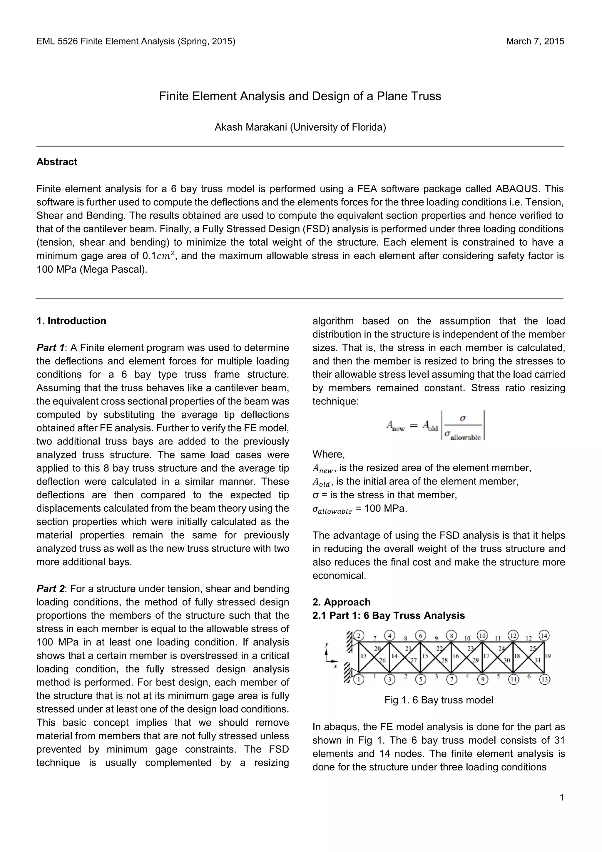
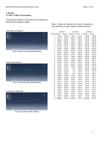
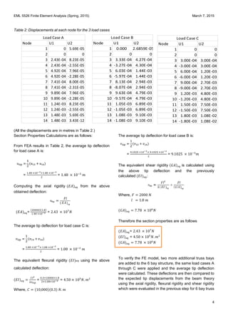
A finite element analysis was performed on a 6 bay plane truss structure using ABAQUS software to determine deflections and member forces under tension, shear, and bending loads. The results were used to calculate equivalent cross-sectional properties, assuming the truss behaved like a cantilever beam. Additional analysis was conducted using fully stressed design to minimize the structure's weight by resizing members to be fully stressed at their allowable limit of 100 MPa under at least one load case, while maintaining a minimum gauge of 0.1 cm^2. Iterative resizing reduced member areas and increased stresses until all members were fully stressed at their limits.
Designed a torque arm, with Multi Point Constraints applied to the center of the arm. The FEA software used for this purpose was ABAQUS. The analysis was performed two major element types: Triangular Elements and Quadrilateral Elements, with relatively equal number of nodes in each case and a convergence study was conducted. The aim of the project was to obtain the optimal design parameters of the torque arm by optimization (minimize weight).
ppt about simple stress and strains. use full for B.E. in 3 semester. all content of chapter are covered in this ppt. i hope this is useful fore some peoples.if you like then plz click lick.
Advanced mathematical analysis of chassis integrated platform designed for un...Dr.Vikas Deulgaonkar
The present work deals with advanced mathematical stress analysis of a platform integrated structure mounted on vehicle chassis designed for unconventional type of loading pattern. The perceptible loading cases in the present analysis comprise static load and its effect on the platform/structure by usage of simple shear force & bending moment diagrams. Deflection analysis using conventional Macaulay’s method invokes the structures suitability for the transportation. Present analysis accentuates on the design stage aspects of the platform as this research is a step in proposed doctoral study. A different type of combination of longitudinal and cross members in platform/frame design is formulated. Present design is anticipated after analysis of all possible combinations& orientations of longitudinal and cross members. Determination of section properties of longitudinal and cross members of the platform & deduction of elementary stress based on the unconventional load pattern are the fundamental steps in design and analysis of structure. Peculiarity of this analysis is the usage of combined section modulus of three members for computation of stress. Present research provides a tool that can be used prior to computer aided design and finite element analysis.
Civil Engineering is the Branch of Engineering.The Civil engineering field requires an understanding of core areas including Mechanics of Solids, Structural Mechanics - I, Building Construction Materials, Surveying - I, Geology and Geotechnical Engineering, Structural Mechanics, Building Construction, Water Resources and Irrigation, Environmental Engineering, Transportation Engineering, Construction and Project Management. Ekeeda offers Online Mechanical Engineering Courses for all the Subjects as per the Syllabus Visit us: https://ekeeda.com/streamdetails/stream/civil-engineering
Ekeeda Provides Online Civil Engineering Degree Subjects Courses, Video Lectures for All Engineering Universities. Video Tutorials Covers Subjects of Mechanical Engineering Degree.
Learn Online Courses of Subject Engineering Mechanics of First Year Engineering. Clear the Concepts of Engineering Mechanics Through Video Lectures and PDF Notes. Visit us: https://ekeeda.com/streamdetails/subject/Engineering-Mechanics
Analysis of Stress and Deflection of Cantilever Beam and its Validation Using...IJERA Editor
This study investigates the deflection and stress distribution in a long, slender cantilever beam of uniform
rectangular cross section made of linear elastic material properties that are homogeneous and isotropic. The
deflection of a cantilever beam is essentially a three dimensional problem. An elastic stretching in one direction
is accompanied by a compression in perpendicular directions. The beam is modeled under the action of three
different loading conditions: vertical concentrated
load applied at the free end, uniformly distributed load and uniformly varying load which runs over the whole
span. The weight of the beam is assumed to be negligible. It is also assumed that the beam is inextensible and so
the strains are also negligible. Considering this assumptions at first using the Bernoulli-Euler’s bendingmoment
curvature relationship, the approximate solutions of the cantilever beam was obtained from the general
set of equations. Then assuming a particular set of dimensions, the deflection and stress values of the beam are
calculated analytically. Finite element analysis of the beam was done considering various types of elements
under different loading conditions in ANSYS 14.5. The various numerical results were generated at different
nodal points by taking the origin of the Cartesian coordinate system at the fixed end of the beam. The nodal
solutions were analyzed and compared. On comparing the computational and analytical solutions it was found
that for stresses the 8 node brick element gives the most consistent results and the variation with the analytical
results is minimum.
Stress Analysis of Chain Links in Different Operating Conditionsinventionjournals
The work covers the stress analysis in a 3D model of chain link analitically and numerically, and based on a real model, experimental examination was carried out. First, the cases when the links are vertical to each other and their tensile load were considered. The analysis was done in both work and experimental conditions and also the tensile load just before the chain broke. Second, the position in which the links are rotated for the calculated maximum angle. Experimental analysis of the high resistance chain (high hardness), insignia stress 14x50 G80 E5 was carried out on an universal testing mashine and the results are used for verification of numerical model.
Analysis of Cross-ply Laminate composite under UD load based on CLPT by Ansys...IJERA Editor
In current study the strength of composite material configuration is obtained from the properties of constituent
laminate by using classical laminate plate theory. For the purpose of analysis various configurations of 2 layered
and 4 layered cross ply laminates are used. The material of laminate is supposed to be boron/epoxy having
orthotropic properties. The loading in current study is supposed to be of uniformly distributed load type. For the
analysis purpose software working on finite element analysis logics i.e. Ansys mechanical APDL is used. By the
help of Ansys mechanical APDL the deflection and stress intensity is found out. The effect of variation of
laminate layers is also studied in current study along with the effect of variation of stacking patterns. The current
study will also help to conclude which stacking pattern is best in 2 layered and 4 layered cross ply laminate.
Parametric Optimization of Rectangular Beam Type Load Cell Using Taguchi MethodIJCERT
In this work, Rectangular beam type load cell is considered for stress and strain analysis by using finite element method. The stress analysis is carried out to minimize the weight of Rectangular beam- type load cell without exceeding allowable stress. The intention of the work is to create the geometry of Rectangular beam-type load cell to find out the optimum solution. FEM software HyperWorks11.0.0.39 is using for parametric optimization of Rectangular beam type load cell. If the stress value is within the permissible range, then certain dimensions will be modified to reduce the amount of material needed. The procedure will be repeated until design changes satisfying all the criteria. Experimental verification will be carried out by photo-elasticity technique with the help of suitable instrumentation like Polariscope. Using Photo-elasticity technique, results are crosschecked which gives results very close to FEM technique. Experimental results will be compared with FEM results. With the aid of these tools the designer can develop and modify the design parameters from initial design stage to finalize basic geometry of load cell.
Final Project for the class of "Mechanics of Deformable Solids -
MECH 321, McGill University.
In the following project, FEA Analysis was performed using ABAQUS. The results were then recorded and analyzed for the purpose of investigating the behavior of of a thin plate under various loading and boundary conditions.
Design, Analysis and weight optimization of Crane Hook: A Reviewijsrd.com
Crane hook are highly liable component and are always subjected to failure due to accumulation of large amount of stress which can eventually lead to its failure .In this present work, to study the different design parameter & stress pattern of crane hook in its loaded condition for different cross section, the design and drafting of crane hook will be prepared by using ANSYS 14.5. By finite element analysis, the stress which is to be formed in various cross section are compared with design calculation .The stress concentration factors are used in strength and durability evaluation of structure and machine element. In this work and also we observe the parameter that affects the weight reduction.
Design, Analysis and weight optimization of Crane Hook: A Review
FEA Project 1- Akash Marakani
1. EML 5526 Finite Element Analysis (Spring, 2015) March 7, 2015
1
Finite Element Analysis and Design of a Plane Truss
Akash Marakani (University of Florida)
Abstract
Finite element analysis for a 6 bay truss model is performed using a FEA software package called ABAQUS. This
software is further used to compute the deflections and the elements forces for the three loading conditions i.e. Tension,
Shear and Bending. The results obtained are used to compute the equivalent section properties and hence verified to
that of the cantilever beam. Finally, a Fully Stressed Design (FSD) analysis is performed under three loading conditions
(tension, shear and bending) to minimize the total weight of the structure. Each element is constrained to have a
minimum gage area of 0.1𝑐𝑚2
, and the maximum allowable stress in each element after considering safety factor is
100 MPa (Mega Pascal).
1. Introduction
Part 1: A Finite element program was used to determine
the deflections and element forces for multiple loading
conditions for a 6 bay type truss frame structure.
Assuming that the truss behaves like a cantilever beam,
the equivalent cross sectional properties of the beam was
computed by substituting the average tip deflections
obtained after FE analysis. Further to verify the FE model,
two additional truss bays are added to the previously
analyzed truss structure. The same load cases were
applied to this 8 bay truss structure and the average tip
deflection were calculated in a similar manner. These
deflections are then compared to the expected tip
displacements calculated from the beam theory using the
section properties which were initially calculated as the
material properties remain the same for previously
analyzed truss as well as the new truss structure with two
more additional bays.
Part 2: For a structure under tension, shear and bending
loading conditions, the method of fully stressed design
proportions the members of the structure such that the
stress in each member is equal to the allowable stress of
100 MPa in at least one loading condition. If analysis
shows that a certain member is overstressed in a critical
loading condition, the fully stressed design analysis
method is performed. For best design, each member of
the structure that is not at its minimum gage area is fully
stressed under at least one of the design load conditions.
This basic concept implies that we should remove
material from members that are not fully stressed unless
prevented by minimum gage constraints. The FSD
technique is usually complemented by a resizing
algorithm based on the assumption that the load
distribution in the structure is independent of the member
sizes. That is, the stress in each member is calculated,
and then the member is resized to bring the stresses to
their allowable stress level assuming that the load carried
by members remained constant. Stress ratio resizing
technique:
Where,
𝐴 𝑛𝑒𝑤, is the resized area of the element member,
𝐴 𝑜𝑙𝑑, is the initial area of the element member,
σ = is the stress in that member,
𝜎 𝑎𝑙𝑙𝑜𝑤𝑎𝑏𝑙𝑒 = 100 MPa.
The advantage of using the FSD analysis is that it helps
in reducing the overall weight of the truss structure and
also reduces the final cost and make the structure more
economical.
2. Approach
2.1 Part 1: 6 Bay Truss Analysis
Fig 1. 6 Bay truss model
In abaqus, the FE model analysis is done for the part as
shown in Fig 1. The 6 bay truss model consists of 31
elements and 14 nodes. The finite element analysis is
done for the structure under three loading conditions
2. EML 5526 Finite Element Analysis (Spring, 2015) March 7, 2015
2
Where,
𝐹𝑥13= Force applied at node 13 in x-direction
𝐹𝑥14= Force applied at node 14 in x-direction
𝐹𝑦13= Force applied at node 13 in y-direction
𝐹𝑦14= Force applied at node 14 in y-direction
The horizontal and the vertical members have length𝑙,
while the inclined members have length√2𝑙. Assume the
young’s modulus (𝐸) =100 GPa, Density ρ =7,830 kg/𝑚3
,
cross sectional area A= 1.0𝑐𝑚2
, and 𝑙=0.3m.
For Load Case A, the boundary conditions at node 2 is
fixed in all directions and at node 1 only the x-direction is
constrained but it is free to move in the y direction due to
roller support. Loads are applied at the 13th and the 14th
node in x-direction with a magnitude of 10,000N
(Tension).
For Load Case B, the boundary conditions are the same
as that of the Case A and the loads are applied at the 13th
and 14th node in y-direction with a magnitude of 1,000N
which results in the shearing effect of the truss structure.
For Load Case C, Similar BC’s are applied to the previous
case but the loads are acting in opposite direction at the
13th and the 14th node which results in a couple and
therefore bending of the truss structure.
Further a FE program is used to determine the deflections
and element force in each truss element. Deflections and
element force at each node are tabulated.
Assuming that the truss behaves like a cantilever beam,
the obtained average tip deflections are used to compute
the equivalent cross sectional properties of the beam i.e.
axial rigidity ( 𝐸𝐴 )eq, flexural rigidity ( 𝐸𝐼 )eq and shear
rigidity (𝐺𝐴)eq using the given formulae.
The deflection of a beam due to an axial force F is given
by:
The transverse deflection due to a transverse force F at
the tip is:
The transverse deflection due to an end couple C is
given by:
Where,
𝑙= Length of the beam (6x0.3 = 1.8 m)
To verify the FE model, two additional bays are added to
the 6 bay truss structure. The same load cases A, B, C
are applied and the average tip deflections were
calculated using an FE program as done before for a 6
bay structure. These deflections are then compared to
the expected tip displacements calculated from the beam
theory formulation using the axial rigidity, flexural rigidity
and shear rigidity calculated in the previous step (where
𝑙=2.4m). Finally, the FE results are compared with the
theoretical results calculated.
2.2 Part 2: FSD Optimization
Fully stressed design is performed on the original 6 bay
structure under three loading conditions (tension, shear
and bending) to find the best design by reducing the
weight and the overall cost of the truss structure. This
basic concept implies that we should remove the material
from the members that are not fully stressed unless
prevented by a minimum gage area of 0.1𝑐𝑚2
.
After performing the analysis for all the three load cases
separately we will have 3 stresses for each member. I
designed the cross sectional area based upon the highest
stress using the resizing algorithm. If the new area Anew
obtained from the resizing formula is smaller than the
minimum gage area (0.1𝑐𝑚2
), the minimum gage area
should be selected rather than the obtained value.
To ensure that the member elements are fully stressed, I
have used Microsoft Excel to perform several iterations
to reduce the area of the member element and increase
the stress value up to the allowable stress of 100MPa.
Therefore, after 10 iterations I could increase the stress
in each member element by reducing the area and
converging the area to the minimum gage area of 0.1𝑐𝑚2
.
After I did this a few times, I found that all the element
stresses are ≤100MPa in any one of the load conditions
and found the weight to be lesser than the initial structure.
Since the truss structure is fully stressed and the final
weight is less we can conclude that the structure is
optimized.
3. EML 5526 Finite Element Analysis (Spring, 2015) March 7, 2015
3
3. Results
3.1 Part 1: 6 Bay Truss Analysis
The deformed structure in the three load conditions are
obtained from Abaqus as follows
Load Case A (Tension)
Fig 2. 6 bay truss under tensile loading
Load Case B (Shear)
Fig 3. 6 bay truss under shear loading
Load Case C (Bending)
Fig 4. 6 bay truss under bending
Table 1. Stress (in Pascals) and Force (in Newtons) at
each element for Tension, Shear and Bending Cases.
Element Stress (Pa) Force (N) Stress (Pa) Force (N) Stress (Pa) Force (N)
1 8.10E+07 8.10E+03 1.11E+08 1.11E+04 1.00E+08 1.00E+04
2 8.30E+07 8.30E+03 8.99E+07 8.99E+03 1.00E+08 1.00E+04
3 8.28E+07 8.28E+03 7.00E+07 7.00E+03 1.00E+08 1.00E+04
4 8.28E+07 8.28E+03 5.00E+07 5.00E+03 1.00E+08 1.00E+04
5 8.30E+07 8.30E+03 3.00E+07 3.00E+03 1.00E+08 1.00E+04
6 8.10E+07 8.10E+03 1.00E+07 1.00E+03 1.00E+08 1.00E+04
7 8.10E+07 8.10E+03 -1.09E+08 -1.09E+04 -1.00E+08 -1.00E+04
8 8.30E+07 8.30E+03 -9.01E+07 -9.01E+03 -1.00E+08 -1.00E+04
9 8.28E+07 8.28E+03 -7.00E+07 -7.00E+03 -1.00E+08 -1.00E+04
10 8.28E+07 8.28E+03 -5.00E+07 -5.00E+03 -1.00E+08 -1.00E+04
11 8.30E+07 8.30E+03 -3.00E+07 -3.00E+03 -1.00E+08 -1.00E+04
12 8.10E+07 8.10E+03 -1.00E+07 -1.00E+03 -1.00E+08 -1.00E+04
13 -1.90E+07 -1.90E+03 -8.95E+06 -8.95E+02 -2.80E-07 -2.80E-11
14 -3.59E+07 -3.59E+03 9.37E+05 9.37E+01 -4.34E-08 -4.34E-12
15 -3.41E+07 -3.41E+03 -9.81E+04 -9.81E+00 0.00E+00 0.00E+00
16 -3.44E+07 -3.44E+03 1.03E+04 1.03E+00 -1.73E-07 -1.73E-11
17 -3.41E+07 -3.41E+03 -1075 -1.08E-01 0.00E+00 0.00E+00
18 -3.59E+07 -3.59E+03 112.7 1.13E-02 3.47E-07 3.47E-11
19 -1.90E+07 -1.90E+03 -13.02 -1.30E-03 -6.94E-07 -6.94E-11
20 2.68E+07 2.68E+03 1.27E+07 1.27E+03 3.90E-07 3.90E-11
21 2.40E+07 2.40E+03 1.43E+07 1.43E+03 5.20E-07 5.20E-11
22 2.43E+07 2.43E+03 1.41E+07 1.41E+03 5.20E-07 5.20E-11
23 2.43E+07 2.43E+03 1.41E+07 1.41E+03 6.94E-07 6.94E-11
24 2.40E+07 2.40E+03 1.41E+07 1.41E+03 3.47E-07 3.47E-11
25 2.68E+07 2.68E+03 1.41E+07 1.41E+03 -3.47E-07 -3.47E-11
26 2.68E+07 2.68E+03 -1.56E+07 -1.56E+03 -3.69E-07 -3.69E-11
27 2.40E+07 2.40E+03 -1.40E+07 -1.40E+03 -4.34E-07 -4.34E-11
28 2.43E+07 2.43E+03 -1.42E+07 -1.42E+03 -4.34E-07 -4.34E-11
29 2.43E+07 2.43E+03 -1.41E+07 -1.41E+03 -6.94E-07 -6.94E-11
30 2.40E+07 2.40E+03 -1.41E+07 -1.41E+03 -1.73E-07 -1.73E-11
31 2.68E+07 2.68E+03 -1.41E+07 -1.41E+03 0.00E+00 0.00E+00
LoadCase A LoadCase B LoadCase C
4. EML 5526 Finite Element Analysis (Spring, 2015) March 7, 2015
4
Table 2: Displacements at each node for the 3 load cases
(All the displacements are in metres in Table 2.)
Section Properties Calculations are as follows:
From FEA results in Table 2, the average tip deflection
for load case A is:
=
1.48 ×10⁻³+1.48 ×10⁻³
2
= 1.48 × 10⁻³
𝑚
Computing the axial rigidity (𝐸𝐴) 𝑒𝑞 from the above
obtained deflection:
(𝐸𝐴) 𝑒𝑞=
(20000)(1.8)
1.48 ×10−3 = 2.43 × 10⁷
𝑁
The average tip deflection for load case C is:
=
1.08 ×10⁻²+ 1.08 ×10⁻²
2
= 1.08 × 10⁻²
𝑚
The equivalent flexural rigidity (𝐸𝐼) 𝑒𝑞 using the above
calculated deflection:
(𝐸𝐼) 𝑒𝑞 =
𝐶𝑙2
2𝑣 𝑡𝑖𝑝
=
0.3×10000×1.8
2×1.08×10−2 = 4.50 × 10⁵
𝑁. 𝑚2
Where, 𝐶 = (10,000)(0.3) 𝑁. 𝑚
The average tip deflection for load case B is:
=
9.1025 ×10⁻³+ 9.1025 ×10⁻³
2
= 9.1025 × 10⁻³
𝑚
The equivalent shear rigidity (𝐺𝐴) 𝑒𝑞 is calculated using
the above tip deflection and the previously
calculated (𝐸𝐼) 𝑒𝑞:
Where, 𝐹 = 2000 𝑁
𝑙 = 1.8 𝑚
(𝐺𝐴) 𝑒𝑞 = 7.78 × 10⁶
𝑁
Therefore the section properties are as follows
(𝐸𝐴) 𝑒𝑞= 2.43 × 10⁷
𝑁
(𝐸𝐼) 𝑒𝑞 = 4.50 × 10⁵
𝑁. 𝑚2
(𝐺𝐴) 𝑒𝑞 = 7.78 × 10⁶
𝑁
To verify the FE model, two more additional truss bays
are added to the 6 bay structure, the same load cases A
through C were applied and the average tip deflection
were calculated. These deflections are then compared to
the expected tip displacements from the beam theory
using the axial rigidity, flexural rigidity and shear rigidity
which were evaluated in the previous step for 6 bay truss
Node U1 U2
1 0 5.69E-05
2 0 0
3 2.43E-04 8.23E-05
4 2.43E-04 -2.55E-05
5 4.92E-04 7.96E-05
6 4.92E-04 -2.28E-05
7 7.41E-04 8.00E-05
8 7.41E-04 -2.31E-05
9 9.89E-04 7.96E-05
10 9.89E-04 -2.28E-05
11 1.24E-03 8.23E-05
12 1.24E-03 -2.55E-05
13 1.48E-03 5.69E-05
14 1.48E-03 3.43E-12
Load Case A
Node U1 U2
1 0.000 2.6859E-05
2 0 0
3 3.33E-04 4.27E-04
4 -3.27E-04 4.30E-04
5 6.03E-04 1.44E-03
6 -5.97E-04 1.44E-03
7 8.13E-04 2.94E-03
8 -8.07E-04 2.94E-03
9 9.63E-04 4.79E-03
10 -9.57E-04 4.79E-03
11 1.05E-03 6.89E-03
12 -1.05E-03 6.89E-03
13 1.08E-03 9.10E-03
14 -1.08E-03 9.10E-03
Load Case B
Node U1 U2
1 0 0
2 0 0
3 3.00E-04 3.00E-04
4 -3.00E-04 3.00E-04
5 6.00E-04 1.20E-03
6 -6.00E-04 1.20E-03
7 9.00E-04 2.70E-03
8 -9.00E-04 2.70E-03
9 1.20E-03 4.80E-03
10 -1.20E-03 4.80E-03
11 1.50E-03 7.50E-03
12 -1.50E-03 7.50E-03
13 1.80E-03 1.08E-02
14 -1.80E-03 1.08E-02
Load Case C
5. EML 5526 Finite Element Analysis (Spring, 2015) March 7, 2015
5
structure (where 𝑙 = 2.4 𝑚). The comparison of the FEA
results and beam theory calculations are tabulated below.
Table 3: Comparisons of tip displacements (in metres)
from FEA results and Beam Theory formulation for 8 bay
truss structure
Therefore, we can conclude that the FE model accurately
predicts the tip deflection for the 8 bay truss element.
3.2 Part 2: 6 bay Truss Optimization
An optimized truss structure was designed after
performing 10 iteration on Microsoft Excel to reduce the
area of each element and to ensure that the stress in
each element is fully stressed and has a maximum value
of 100MPa (≤100 MPa). The final obtained stress values
for the optimized case have been shown in Table 4.
Table 4: Element Stresses (in Pascals) for the final
iteration.
The most critical load case for each element and the
corresponding areas have been tabulated in Table 5.
Element Load Case A Load Case B Load Case C
1 8.61E+07 1.01E+08 8.84E+07
2 9.76E+07 8.85E+07 1.00E+08
3 9.76E+07 7.03E+07 1.00E+08
4 9.75E+07 4.97E+07 1.00E+08
5 9.76E+07 3.00E+07 1.00E+08
6 9.72E+07 9.68E+06 1.00E+08
7 9.14E+07 -9.94E+07 -9.36E+07
8 9.76E+07 -9.15E+07 -1.00E+08
9 9.76E+07 -6.97E+07 -1.00E+08
10 9.76E+07 -5.03E+07 -1.00E+08
11 9.76E+07 -3.00E+07 -1.00E+08
12 9.72E+07 -1.03E+07 -1.00E+08
13 -2.43E+07 -6.07E+07 8.56E+05
14 -4.84E+07 2.40E+07 7.12E+05
15 -4.86E+07 -1.19E+07 -1.19E+05
16 -4.89E+07 7.64E+05 2.01E+04
17 -4.82E+07 -2.44E+06 -2329
18 -5.22E+07 -3.00E+06 1388
19 -2.84E+07 -3.17E+06 -267
20 3.43E+07 8.59E+07 -1.21E+06
21 2.13E+07 1.02E+08 1.27E+05
22 2.46E+07 9.72E+07 -2.42E+04
23 2.37E+07 9.93E+07 3855
24 2.34E+07 9.85E+07 -1633
25 2.70E+07 9.81E+07 253.9
26 1.81E+07 -1.04E+08 -6.37E+05
27 2.78E+07 -9.75E+07 1.65E+05
28 2.42E+07 -1.02E+08 -2.38E+04
29 2.53E+07 -1.00E+08 4107
30 2.40E+07 -1.01E+08 -1672
31 2.98E+07 -1.02E+08 279.9
FE Model Beam Theory
- -
FE Model Beam Theory
- -
FE Model Beam Theory
- -
Load Case A
Load Case B
Load Case C
1.97 × 10⁻³
1.97 × 10⁻³
2.1 × 10⁻²
2.1 × 10⁻²
1.92 × 10⁻² 1.92 × 10⁻²
6. EML 5526 Finite Element Analysis (Spring, 2015) March 7, 2015
6
Table 5: Element stress (in Pascals), Critical load case
and element areas (m2).
Weight of the truss = ∑ (volume of all elements) * ρ
𝑉𝑜𝑙 𝑚𝑒 = 𝐴𝑟𝑒𝑎 × 𝑙𝑒𝑛𝑔𝑡ℎ 𝑜𝑓 𝑒𝑙𝑒𝑚𝑒𝑛𝑡
𝐿𝑒𝑛𝑔𝑡ℎ 𝑜𝑓 𝑒𝑙𝑒𝑚𝑒𝑛𝑡 = 0.3 𝑚
𝐷𝑒𝑛𝑠𝑖𝑡𝑦 (𝜌) = 7,830
𝑘𝑔
𝑚3
Final Weight of the Truss = 3.43 𝒌𝒈
4. Conclusions
After the FEA analysis, the tip displacements for the 6 bay
plane truss structure were computed which were further
used to find out the sectional properties using the beam
theory formulation. Hence, we can conclude that the truss
structure behaves like a cantilever beam. Moreover,
using the Fully Stressed Design (FSD) technique
unwanted material was removed from the frame structure
which helped in reducing the overall weight of the truss
structure which helped us in coming with the most
optimized design for the structure. The final weight of the
6 bay truss is computed to be 3.43 𝒌𝒈𝒔.
5. Appendix
The input file for 6 bay truss element has been elaborated
as follows;
Firstly, the nodes are defined in the similar manner. Node
1 location is specified at (0, 0).
*Node
1, 0, 0.
Next, the element type is specified along with the element
connectivity table which specifies which two nodes are
connected by the element. Example, Element 1 connects
node 1 and node 3.
*Element, type=T2D2
1, 1, 3
*Nset, nset=SET-1, generate
1, 14, 1 (Specifies the total number of nodes)
*Elset, elset=SET-1, generate
1, 31, 1 (Specifies the total number of elements)
Next, after the assembly of the part the cross sectional
area and material properties are defined and assigned to
the respective element.
** Section: Section-1-SET-1
*Solid Section, elset=SET-1, material=MATERIAL-1
0.0001,
** MATERIALS
**
*Material, name=MATERIAL-1
*Density
7830.,
*Elastic
Element Max StressCritical Case Area (m^2)
1 1E+08 B 0.000113924
2 1E+08 C 9.99755E-05
3 1E+08 C 0.000100001
4 1E+08 C 9.99991E-05
5 1E+08 C 9.99994E-05
6 1E+08 C 1E-04
7 9.9E+07 B 0.000106071
8 1E+08 C 0.00010001
9 1E+08 C 9.99936E-05
10 1E+08 C 9.99999E-05
11 1E+08 C 9.99951E-05
12 1E+08 C 0.0001
13 6.1E+07 B 0.00001
14 4.8E+07 A 0.00001
15 4.9E+07 A 0.00001
16 4.9E+07 A 0.00001
17 4.8E+07 A 0.00001
18 5.2E+07 A 0.00001
19 2.8E+07 A 0.00001
20 8.6E+07 B 0.00001
21 1E+08 B 1.63069E-05
22 9.7E+07 B 1.36647E-05
23 9.9E+07 B 1.4511E-05
24 9.8E+07 B 1.41179E-05
25 9.8E+07 B 1.45904E-05
26 1E+08 B 1.96951E-05
27 9.7E+07 B 1.19782E-05
28 1E+08 B 1.46198E-05
29 1E+08 B 1.37731E-05
30 1E+08 B 1.41935E-05
31 1E+08 B 1.36934E-05
7. EML 5526 Finite Element Analysis (Spring, 2015) March 7, 2015
7
1e+11, 0.
Next, the boundary conditions and the loads are assigned
** BOUNDARY CONDITIONS
**
** Name: Disp-BC-1
Type: Symmetry/Antisymmetry/Encastre
*Boundary
SET-3, ENCASTRE
** Name: Disp-BC-2 Type: Displacement/Rotation
*Boundary
SET-4, 1, 1
** ----------------------------------------------------------------
**
** STEP: Step-1
**
*Step, name=Step-1, nlgeom=NO, perturbation
*Static
**
** LOADS
**
** Name: CFORCE-1 Type: Concentrated force
*Cload
SET-5, 1, 10000.
** Name: CFORCE-3 Type: Concentrated force
*Cload
SET-6, 1, 10000.
**
Next, the stress value and the nodal displacements which
are needed for the calculation are printed in the output
requests section
** OUTPUT REQUESTS
**
**
** FIELD OUTPUT: F-Output-1
*EL PRINT
S
*NODE PRINT
U
**
*Output, field, variable=PRESELECT
**
** HISTORY OUTPUT: H-Output-1
**
*Output, history, variable=PRESELECT
*End Step
In the similar manner another step is created for the shear
and bending case.
To do the analysis for an 8 bay truss element the input
file is edited according to our requirement to perform the
analysis.
For an FSD analysis for a 6 bay truss element, the steps
are almost the same just that each element needs to be
assigned a different cross sectional property and each
element needs to be defined separately. As the cross
sectional area needs to be changed at each and every
iteration.
For Example;
Firstly, element number 12 has been defined
*Elset, elset=SET-12
12,
Next, a cross sectional area of 0.0001 m2 is assigned to
that respective element.
** Section: Section-12-SET-12
*Solid Section, elset=SET-12, material=MATERIAL-1
0.0001,
This needs to be followed for 31 elements in case of FSD
analysis and each area needs to be changed in every
iteration and analysis needs to be performed.