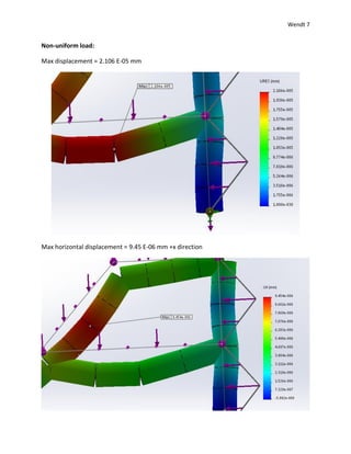
1) The document reports on a beam analysis simulation where beams were subjected to uniform and non-uniform loads.
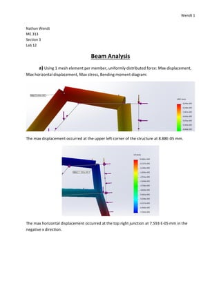
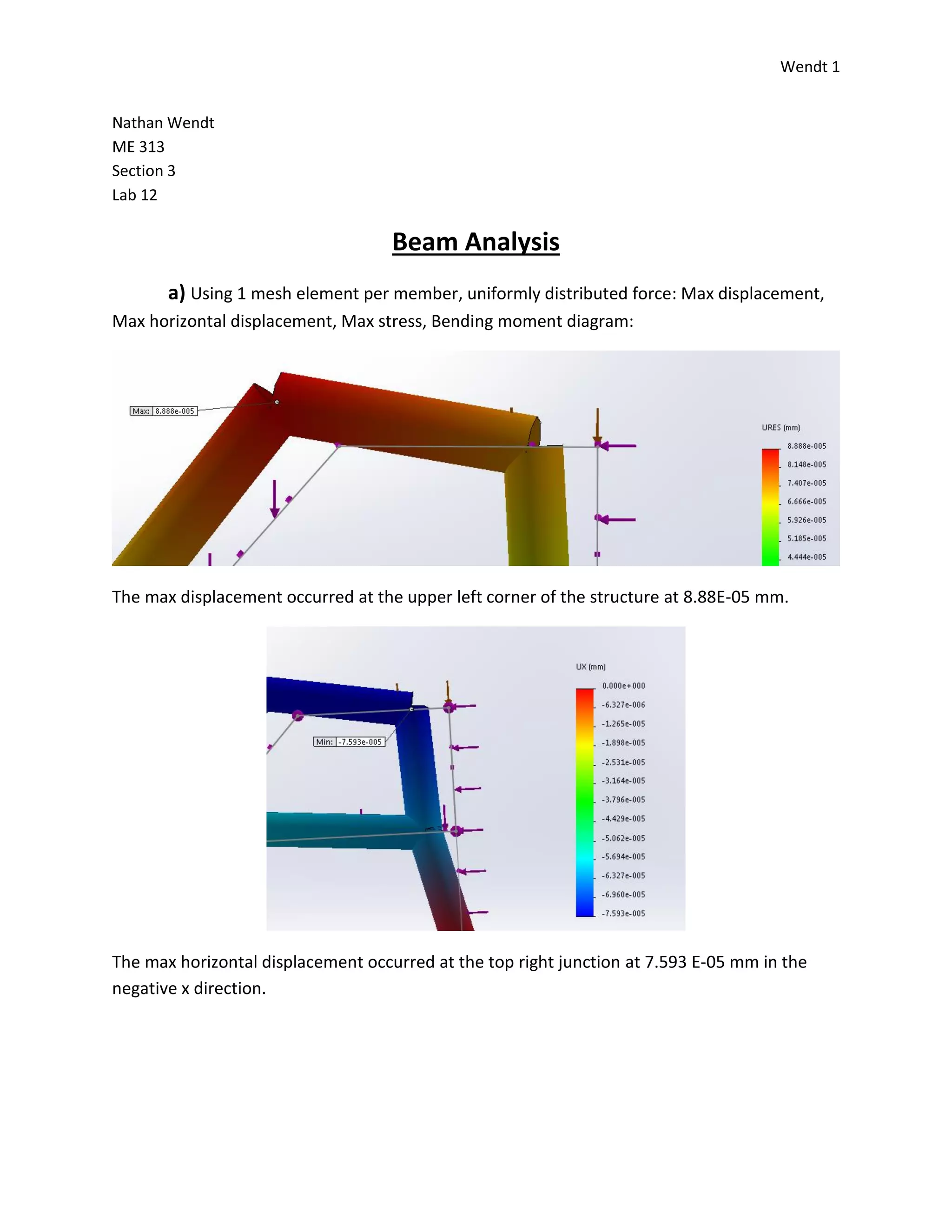
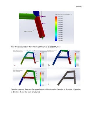
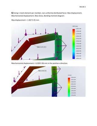
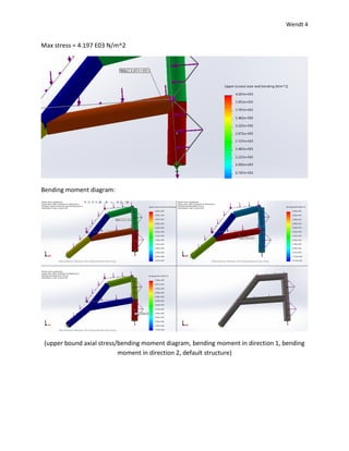
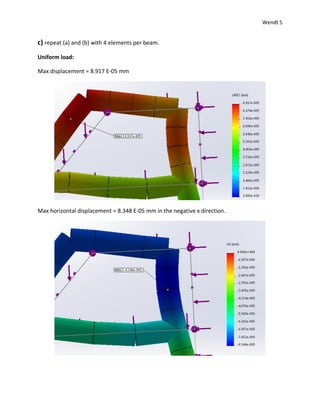
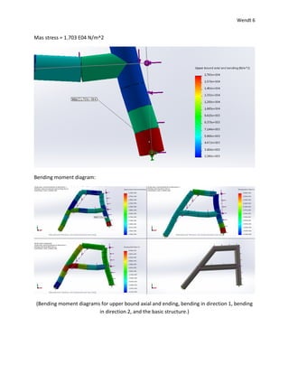
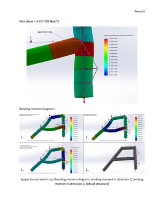
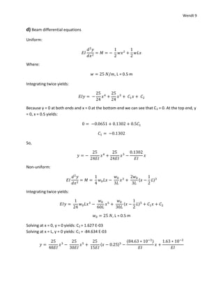
2) Maximum displacements, stresses, and bending moments were reported from the simulation for different mesh element sizes.
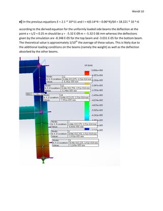
3) Beam differential equations were derived for uniform and non-uniform loads and solved to find theoretical deflections.
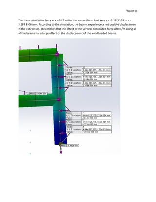
4) The theoretical deflections did not match the simulation results, likely due to additional loading conditions and deflection absorption in the simulation that were not accounted for in the simplified theoretical model.