Downloaded 15 times


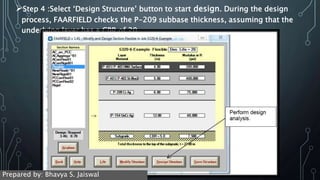
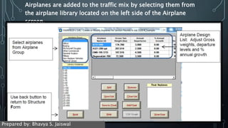
![Step 6 : FAARFIELD includes the ability to evaluate the depth of
subgrade compaction required. After completing your design,
select the ‘Life/Compaction’ button. The design report then
includes a subgrade compaction table for Non-Cohesive and
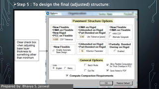
Cohesive subgrade. Check that the “compute compaction
requirements” is selected on the Options Screen (as step3)
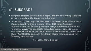
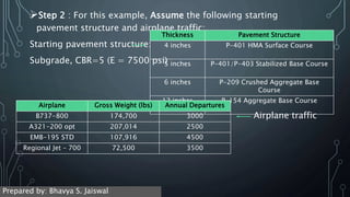
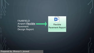
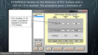
Step 7/8 : The Airport Pavement Design report (next slide) is
automatically saved to a file named as follows: [job
name]_[section name].pdf.into the same working directory that
you designated for your FAARFIELD job files. The report can
also be viewed from the startup screen by selecting ‘Notes’
button. The design report summarizes the Pavement Structure,
Airplane Traffic and the CDF contribution of each aircraft
evaluated.
Prepared by: Bhavya S. Jaiswal](https://image.slidesharecdn.com/airfielddesignmethods-210409080734/85/Airfield-design-methods-18-320.jpg)
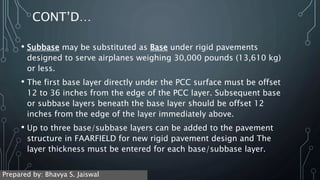
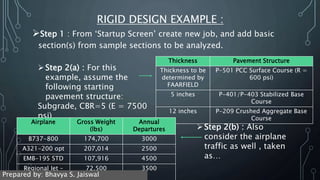
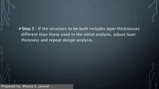
![b) BASE / SUBBASE LAYERS
• The base layer provides a uniform, stable support for the rigid
pavement slabs.
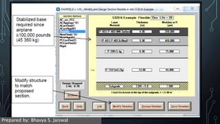
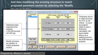
• Stabilized base is required for base under pavements designed
to serve airplanes over 100,000 pounds.
• Two layers of base may be used, e.g. Lean Concrete over a layer
of Crushed aggregate. Layering must be done in such a way as to
avoid producing a sandwich (granular layer between two
stabilized layers) section or a weaker layer over a stronger layer.
[this same concept of sandwiched layer is also avoided in flexible
pavement]
Prepared by: Bhavya S. Jaiswal](https://image.slidesharecdn.com/airfielddesignmethods-210409080734/85/Airfield-design-methods-24-320.jpg)

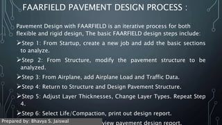


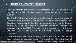
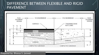
The document discusses airfield pavement design methods, including flexible and rigid pavements. For flexible pavements, it describes the layers of hot mix asphalt surfacing, base course, subbase, and subgrade. It provides minimum thickness requirements for each layer. For rigid pavements, it discusses the concrete surface layer and minimum thicknesses. It also addresses base and subbase layers, subgrade determination, frost protection, concrete strength, and jointing of rigid pavements. The document outlines the iterative FAARFIELD pavement design process used for both flexible and rigid pavements.


