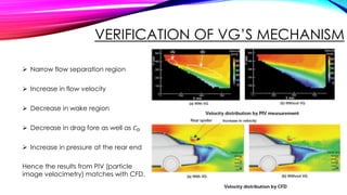
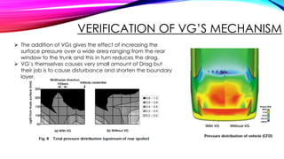
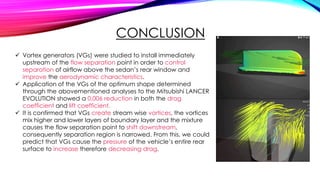
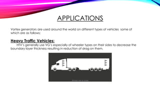
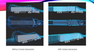
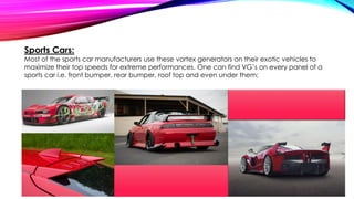
Group 1
GROUP MEMBERS
Syed Muhammad Wajeeh Shah 16-ME-004
Muhammad Safeer Amjad 16-ME-008
Muhammad Bilal 16-ME-020
Muhammad Jehanzeb Malik 16-ME-048
Muhammad Uzair Khan 16-ME-056
Muhammad Ali Mughal 16-ME-144
ABSTRACT
 One of the main causes of aerodynamic drag for sedan vehicles is the separation of flow near
the vehicle’s rear end.
 To delay flow separation, bump-shaped vortex generators are tested for application to the
roof end of a sedan.
 Vortex generators themselves create drag, but they also reduce drag by preventing flow
separation at downstream.
 Since this effect depends on the shape and size of vortex generators, those on the vehicle roof
are optimized.
This paper presents the optimization result, the effect of vortex generators in the flow field and
the mechanism by which these effects take place.
A vortex generator (VG) is an aerodynamic device,
consisting of a small vane usually attached to a
surface where boundary layer thickness has to be
reduced resulting in smaller wake region.
VORTEX GENERATOR
“
”
SOME MAJOR TYPES OF VORTEX
GENERATORS
Vortex
generators
Vane type
Counter
rotating
Co Rotating
Wedge/
Ramp
Forward
facing
Backward
facing
Wheeler
Wishbone Doublet
Cylinder VG
Hemisphere
Bump
SHAPES OP DIFFERENT VG’S
1. Vane Type
2. Wedge/ Ramp Type: 3. Wheeler 4.Cylinder VG 5.Hemesphere Bump
INTRODUCTION
 Drag reduction is meant to improve the fuel efficiency of modern day vehicles.
 To save non renewable fossil fuels and to
protect the global environment is the
concern of every automotive manufacturer.
 Engineers tried their best to reduce Drag by
making vehicle’s bodies streamline to make them more aerodynamic.
 But still couldn’t found any method to vanish the wake region behind the vehicles.
MECHANISM OF FLOW SEPARATION
AND OBJECTIVES
OF ADDING VORTEX GENERATORS
 The vehicle height from the rear end is progressively lower as the flow moves downstream, an
expanded airflow is formed there.
 This causes the downstream pressure to rise, which in turn creates reverse force acting against
the main flow and generates reverse flow.
 This reverse flow Results in the creation of Wake Region a the rear end of the vehicle.
MECHANISM OF FLOW SEPARATION AND
OBJECTIVES
OF ADDING VORTEX GENERATORS
 No reverse flow occurs at Point A located.
 Further upstream of Point C because the momentum
of the boundary layer is prevailing over the pressure
gradient (dp/dx).
 Between Points A and C, there is separation Point B,
where the pressure gradient and the momentum of
the boundary layer are balanced.
MECHANISM OF FLOW SEPARATION AND
OBJECTIVES
OF ADDING VORTEX GENERATORS
 In the lower zone close to the vehicle’s surface within
the boundary layer, the airflow quickly loses
momentum as it moves downstream due to the
viscosity of air.
 The purpose of adding VGs is to supply the
momentum from higher region where has large
momentum to lower region where has small
momentum by stream wise vortices generated from
VGs located just before the separation point.
FINDING THE OPTIMUM VGS
To select appropriate shape and size of the VG which generates stream wise vortex the most
efficiently (with the least drag by itself) is important to achieve objectives.
 Optimum height of the VG would be nearly equal to the
boundary layer thickness.
 As to the shape, a bump-shaped piece with a rear slope angle
of 25 to 30° is selected. A half-span delta wing shape is also
recommended for the VG.
 As to the location of VGs, a point immediately upstream of the flow separation point was
assumed to be optimum, and a point 100 mm in front of the roof end was selected.
FINDING THE OPTIMUM VGS
2 h
2h +3h h
VERIFICATION OF VG’S MECHANISM
 Narrow flow separation region
 Increase in flow velocity
 Decrease in wake region
 Decrease in drag fore as well as 𝐶 𝐷
 Increase in pressure at the rear end
Hence the results from PIV (particle
image velocimetry) matches with CFD.
VERIFICATION OF VG’S MECHANISM
 The addition of VGs gives the effect of increasing the
surface pressure over a wide area ranging from the rear
window to the trunk and this in turn reduces the drag.
 VG’s themselves causes very small amount of Drag but
their job is to cause disturbance and shorten the boundary
layer.
CONCLUSION
 Vortex generators (VGs) were studied to install immediately
upstream of the flow separation point in order to control
separation of airflow above the sedan’s rear window and
improve the aerodynamic characteristics.
 Application of the VGs of the optimum shape determined
through the abovementioned analyses to the Mitsubishi LANCER
EVOLUTION showed a 0.006 reduction in both the drag
coefficient and lift coefficient.
 It is confirmed that VGs create stream wise vortices, the vortices
mix higher and lower layers of boundary layer and the mixture
causes the flow separation point to shift downstream,
consequently separation region is narrowed. From this, we could
predict that VGs cause the pressure of the vehicle’s entire rear
surface to increase therefore decreasing drag.
APPLICATIONS
Vortex generators are used around the world on different types of vehicles some of
which are as follows;
Heavy Traffic Vehicles:
HTV’s generally use VG’s especially of wheeler types on their sides to decrease the
boundary layer thickness resulting in reduction of drag on them.
Without Vortex Generator With Vortex Generator
Passenger Cars (Sedans):
Nowadays it is an important part of modern day vehicles. Toyota has been successfully using
VG’s on their best selling models to improve their fuel consumption. We can observe this in the given
example;
Sports Cars:
Most of the sports car manufacturers use these vortex generators on their exotic vehicles to
maximize their top speeds for extreme performances. One can find VG’s on every panel of a
sports car i.e. front bumper, rear bumper, roof top and even under them;
THANKS

Aerodynamic drag reduction by vortex generator

  • 1.
  • 2.
    GROUP MEMBERS Syed MuhammadWajeeh Shah 16-ME-004 Muhammad Safeer Amjad 16-ME-008 Muhammad Bilal 16-ME-020 Muhammad Jehanzeb Malik 16-ME-048 Muhammad Uzair Khan 16-ME-056 Muhammad Ali Mughal 16-ME-144
  • 3.
    ABSTRACT  One ofthe main causes of aerodynamic drag for sedan vehicles is the separation of flow near the vehicle’s rear end.  To delay flow separation, bump-shaped vortex generators are tested for application to the roof end of a sedan.  Vortex generators themselves create drag, but they also reduce drag by preventing flow separation at downstream.  Since this effect depends on the shape and size of vortex generators, those on the vehicle roof are optimized. This paper presents the optimization result, the effect of vortex generators in the flow field and the mechanism by which these effects take place.
  • 4.
    A vortex generator(VG) is an aerodynamic device, consisting of a small vane usually attached to a surface where boundary layer thickness has to be reduced resulting in smaller wake region. VORTEX GENERATOR “ ”
  • 5.
    SOME MAJOR TYPESOF VORTEX GENERATORS Vortex generators Vane type Counter rotating Co Rotating Wedge/ Ramp Forward facing Backward facing Wheeler Wishbone Doublet Cylinder VG Hemisphere Bump
  • 6.
    SHAPES OP DIFFERENTVG’S 1. Vane Type
  • 7.
    2. Wedge/ RampType: 3. Wheeler 4.Cylinder VG 5.Hemesphere Bump
  • 8.
    INTRODUCTION  Drag reductionis meant to improve the fuel efficiency of modern day vehicles.  To save non renewable fossil fuels and to protect the global environment is the concern of every automotive manufacturer.  Engineers tried their best to reduce Drag by making vehicle’s bodies streamline to make them more aerodynamic.  But still couldn’t found any method to vanish the wake region behind the vehicles.
  • 9.
    MECHANISM OF FLOWSEPARATION AND OBJECTIVES OF ADDING VORTEX GENERATORS  The vehicle height from the rear end is progressively lower as the flow moves downstream, an expanded airflow is formed there.  This causes the downstream pressure to rise, which in turn creates reverse force acting against the main flow and generates reverse flow.  This reverse flow Results in the creation of Wake Region a the rear end of the vehicle.
  • 10.
    MECHANISM OF FLOWSEPARATION AND OBJECTIVES OF ADDING VORTEX GENERATORS  No reverse flow occurs at Point A located.  Further upstream of Point C because the momentum of the boundary layer is prevailing over the pressure gradient (dp/dx).  Between Points A and C, there is separation Point B, where the pressure gradient and the momentum of the boundary layer are balanced.
  • 11.
    MECHANISM OF FLOWSEPARATION AND OBJECTIVES OF ADDING VORTEX GENERATORS  In the lower zone close to the vehicle’s surface within the boundary layer, the airflow quickly loses momentum as it moves downstream due to the viscosity of air.  The purpose of adding VGs is to supply the momentum from higher region where has large momentum to lower region where has small momentum by stream wise vortices generated from VGs located just before the separation point.
  • 12.
    FINDING THE OPTIMUMVGS To select appropriate shape and size of the VG which generates stream wise vortex the most efficiently (with the least drag by itself) is important to achieve objectives.  Optimum height of the VG would be nearly equal to the boundary layer thickness.  As to the shape, a bump-shaped piece with a rear slope angle of 25 to 30° is selected. A half-span delta wing shape is also recommended for the VG.  As to the location of VGs, a point immediately upstream of the flow separation point was assumed to be optimum, and a point 100 mm in front of the roof end was selected.
  • 13.
    FINDING THE OPTIMUMVGS 2 h 2h +3h h
  • 14.
    VERIFICATION OF VG’SMECHANISM  Narrow flow separation region  Increase in flow velocity  Decrease in wake region  Decrease in drag fore as well as 𝐶 𝐷  Increase in pressure at the rear end Hence the results from PIV (particle image velocimetry) matches with CFD.
  • 15.
    VERIFICATION OF VG’SMECHANISM  The addition of VGs gives the effect of increasing the surface pressure over a wide area ranging from the rear window to the trunk and this in turn reduces the drag.  VG’s themselves causes very small amount of Drag but their job is to cause disturbance and shorten the boundary layer.
  • 16.
    CONCLUSION  Vortex generators(VGs) were studied to install immediately upstream of the flow separation point in order to control separation of airflow above the sedan’s rear window and improve the aerodynamic characteristics.  Application of the VGs of the optimum shape determined through the abovementioned analyses to the Mitsubishi LANCER EVOLUTION showed a 0.006 reduction in both the drag coefficient and lift coefficient.  It is confirmed that VGs create stream wise vortices, the vortices mix higher and lower layers of boundary layer and the mixture causes the flow separation point to shift downstream, consequently separation region is narrowed. From this, we could predict that VGs cause the pressure of the vehicle’s entire rear surface to increase therefore decreasing drag.
  • 17.
    APPLICATIONS Vortex generators areused around the world on different types of vehicles some of which are as follows; Heavy Traffic Vehicles: HTV’s generally use VG’s especially of wheeler types on their sides to decrease the boundary layer thickness resulting in reduction of drag on them.
  • 18.
    Without Vortex GeneratorWith Vortex Generator
  • 19.
    Passenger Cars (Sedans): Nowadaysit is an important part of modern day vehicles. Toyota has been successfully using VG’s on their best selling models to improve their fuel consumption. We can observe this in the given example;
  • 20.
    Sports Cars: Most ofthe sports car manufacturers use these vortex generators on their exotic vehicles to maximize their top speeds for extreme performances. One can find VG’s on every panel of a sports car i.e. front bumper, rear bumper, roof top and even under them;
  • 21.