AERODYNAMIC ANALYSIS OF RAMP TYPE VORTEX GENERATOR ON NACA 2215 AIRFOIL
•
0 likes•11 views

The document discusses the aerodynamic analysis of ramp type vortex generators on a NACA 2215 airfoil. Vortex generators are designed to delay flow separation and increase stall angle. The study models a wing with and without vortex generators using ANSYS software. Results show that vortex generators delay stall by 4 degrees and increase maximum lift compared to a normal wing. Vortex generators improve aerodynamic performance by mixing high-energy outer flow with lower-energy boundary layer flow.

Recommended
Recommended
More Related Content
Similar to AERODYNAMIC ANALYSIS OF RAMP TYPE VORTEX GENERATOR ON NACA 2215 AIRFOIL
Similar to AERODYNAMIC ANALYSIS OF RAMP TYPE VORTEX GENERATOR ON NACA 2215 AIRFOIL (20)
More from IRJET Journal
More from IRJET Journal (20)
Recently uploaded
Recently uploaded (20)
AERODYNAMIC ANALYSIS OF RAMP TYPE VORTEX GENERATOR ON NACA 2215 AIRFOIL
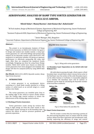
- 1. © 2023, IRJET | Impact Factor value: 8.226 | ISO 9001:2008 Certified Journal | Page 271 AERODYNAMIC ANALYSIS OF RAMP TYPE VORTEX GENERATOR ON NACA 2215 AIRFOIL Nilesh Nahar1, Manoj Sharma2, Amit Kumar Jha3, Rahul Joshi4 1 M.Tech student, Design of Mechanical Systems, Department of Mechanical Engineering, Swami Vivekanand College of Engineering, M.P. 2 Assistant Professor& HOD, Department of Mechanical Engineering, Swami Vivekanand College of Engineering, M.P. 3 Senior Manager, HAL, Bangalore 4 Associate Professor, Department of Mechanical Engineering, Swami Vivekanand College of Engineering, M.P. ---------------------------------------------------------------------***--------------------------------------------------------------------- Abstract – The project is on Aerodynamic Analysis of Ramp Type Vortex Generator on NACA 2215 Airfoil. Our goal is to design and analyze two models namely a ramp type vortex generator on a 3D airfoil (Wing) and normal wing without VG for Reynolds number value 68.47x10^5. We analyzed it to determine whether VG giving an optimum performance in effectively postponing the wing stall angle. After that, we compared the analytical results accordingly. Designing was done by using Ansys Design modeler. NACA 2215 airfoil were chosen on which the vortex generators have been designed and modeled. The design will then be analyzed (CFD) by using ANSYS R20 software. Key Words: NACA 2215, ANSYS, Reynolds number, Ramp Type Vortex Generator 1. INTRODUCTION A vortex generator is an aerodynamic device consisting of a small blade usually attached to a lifting surface or airfoil (such as an aircraft wing) or a wind turbine rotor blade. The vortex generators are installed quite close to the leading edge of the airfoil to ensure steady airflow over the trailing edge control surfaces to ensure the effectiveness of the trailing edge control surfaces. 1.1 Working of Vortex Generators Vortex generators create strong tip vortices that bring in high energy air from the outer nozzle to mix with/replace slower moving air in the boundary layer. It reduces the effects of adverse pressure gradients and prevents separation. Fig 1.1: Wing with vortex generators 1.2 Boundary Layer Separation on An Airfoil with And Without VG’s All solid objects passing through a fluid acquire a fluid boundary layer around them, where viscous forces arise in the fluid layer near the surface of the solid. Boundary layers can be either laminar or turbulent. A reasonable judgment as to whether the boundary layer will be laminar or turbulent can be made by calculating the Reynolds number of the local flow conditions. Fig 1.2: Flow before VG and After VG 1.3 Smart Vortex Generators The VG creates a vortex that, by removing a portion of the slow-moving boundary layer in contact with the airfoil surface, delays local flow separation and aerodynamic stall, thereby improving the efficiency of wings and control International Research Journal of Engineering and Technology (IRJET) e-ISSN: 2395-0056 Volume: 10 Issue: 06 | Jun 2023 www.irjet.net p-ISSN: 2395-0072
- 2. International Research Journal of Engineering and Technology (IRJET) e-ISSN: 2395-0056 Volume: 10 Issue: 06 | Jun 2023 www.irjet.net p-ISSN: 2395-0072 © 2023, IRJET | Impact Factor value: 8.226 | ISO 9001:2008 Certified Journal | Page 272 surfaces such as flaps, ailerons, rudders, and elevators. To achieve this, they are often placed on the exterior surfaces of vehicles or load-bearing surfaces. During steady cruise, most vortex generators create drag and must be retractable. Therefore, intelligent vortex generators need to be implemented. The intelligent vortex generator is based on the profile at launch and at low speeds. And they retract when cruising at high speed and altitude. Some concepts for an intelligent vortex generator have already been designed, constructed, and tested. 1.4 Shape Memory Alloys A shape memory alloy is an alloy that can be deformed when cold but returns to its pre-deformed ("remembered") shape when heated. SMA’s can be used as intelligent vortex generators; they change shapes due to changes in atmospheric temperature at different altitudes. Fig 1.3: Example structure of shape memory alloy 1.5 Pneumatic actuators Pneumatic actuators are mechanical devices that use compressed air acting on a piston inside a cylinder to move a load along a linear path. Unlike their hydraulic alternatives, the operating fluid in the pneumatic drive is only air, so leaks do not drip and pollute the surrounding spaces. These pneumatic actuators are used to control vortex generators. Pneumatic actuators can be controlled by an altimeter for height measurement and a speedometer for retracting and extending by measuring height and speed. 2 METHODOLOGIES 3 CFD MODELLING Fig 3.1: Flow Domain
- 3. International Research Journal of Engineering and Technology (IRJET) e-ISSN: 2395-0056 Volume: 10 Issue: 06 | Jun 2023 www.irjet.net p-ISSN: 2395-0072 © 2023, IRJET | Impact Factor value: 8.226 | ISO 9001:2008 Certified Journal | Page 273 The Airfoil design is imported into Workbench Mesh. The domain is created in geometry using the "draw and create" option. A network is created within a network. The mesh size is varied until the desired Skewness, aspect ratio & orthogonal quality is achieved. Fig 3.2: Mesh of the flow domain with & without VG 4 RESULTS AND DISCUSSION This subsection combines the Computational Fluid Dynamic analysis results of a complete analysis of the NACA 2215 airfoil with VG configurations. CFD analysis of the problem, two-dimensional structured mesh with RANS model and S-A turbulence. The aim of the project is to study the aerodynamics flow behavior around the wing with Vg at specified heights of 3 mm and to improve the aerodynamics. 4.1 Pressure Contours of NACA 2215 Airfoil Without VG Pressure Contours of NACA2215 Airfoil without VG at various AoA shown below 4.2 Pressure Contours of NACA 2215 Airfoil of 3mm VG heights angles of attack (-2,0,2,4,8,12,14,16,18,20) Fig 4.1: Pressure Contours of wing without VG at various
- 4. International Research Journal of Engineering and Technology (IRJET) e-ISSN: 2395-0056 Volume: 10 Issue: 06 | Jun 2023 www.irjet.net p-ISSN: 2395-0072 © 2023, IRJET | Impact Factor value: 8.226 | ISO 9001:2008 Certified Journal | Page 274 4.3 Lift and Drag Characteristics The lift and drag characteristics of NACA 2215 airfoil with vg 0.3 mm height at different angle of attack (-2, 0, 2, 4, 8, 12, ..………20) along with Reynolds number (68.47x10⁵ ) are three parameters considered in this case study and the simulation is performed for each height of Re and vg. The results obtained from these parameters are shown below in the table column in terms of Cl and Cd. Re = 68.47 × 10⁵ Fig 4.2: Pressure Contours of wing with VG of height 3mm at various angles of attack (-2,0,2,4,8,12,14,16,18,20) 𝛼 (deg) NACA2215 Airfoil without vg NACA2215 Airfoil with 3mm vg 𝐶𝑙 𝐶𝑑 𝐶𝑙/𝐶𝑑 𝐶𝑙 𝐶𝑑 𝐶𝑙/𝐶𝑑 -2 0.117 0.027 4.33 0.115 0.019 6.05 0 0.31 0.027 11.48 0.304 0.027 11.25 2 0.48 0.045 10.66 0.505 0.05 10.1 4 0.71 0.088 8.068 0.71 0.087 8.16 8 1.1 0.203 5.418 1.08 0.2 5.4 12 1.45 0.37 3.918 1.42 0.36 3.94 14 1.41 0.41 3.439 1.56 0.45 3.46 16 1.36 0.45 3.022 1.65 0.54 3.05 18 1.3 0.54 2.407 1.54 0.62 2.48 20 1.23 0.61 2.016 1.51 0.69 2.18 Table 4.1 Lift and Drag characteristics at Re = 68.47 ×10⁵ 5 CONCLUSIONS With the help of Ansys-Fluent CFD software, CFD analysis of aerodynamic performance of a NACA2215 Airfoil with ramped vortex generator at various angles of attack -2, 0, 2, 4, 8, 12, ..…… …20 degrees with a Reynolds number of 68.47 × 10⁵ using the Spalart-Almaras turbulence model has been done. The results shows that successful delay of flow separation on the NACA 2215 Airfoil with a ramp-type vortex generator as a passive control technique, but not only that it is a pond post. angle of attack but also increased the CL (max) of the NACA 2215 airfoil. For Re = 68.47 × 10⁵ (V= 100 m/s) the VG ramp of 3 mm is shown to be effective in delaying the stall angle by 4 degrees and increasing the CL (max) = 1.65. It can be seen from above that with a 3mm ramp, vg is very effective in delaying the angle of attack of a normal NACA2215 Airfoil. Although the value of Cd is slightly higher than that of a normal wing at a higher angle of attack, the Cl/Cd ratio is higher than that of a normal NACA 2215 wing. REFERENCES [1] Mi, H.Zhan, S.Lu, An extended unsteady aerodynamic model at high angle of attack, Aerosp. Sci. Technol,77,2018 [2] Ramanujam G, Ozdemir and hoeijmakers, improving airfoil drag prediction, AIAA, 2016
- 5. International Research Journal of Engineering and Technology (IRJET) e-ISSN: 2395-0056 Volume: 10 Issue: 06 | Jun 2023 www.irjet.net p-ISSN: 2395-0072 © 2023, IRJET | Impact Factor value: 8.226 | ISO 9001:2008 Certified Journal | Page 275 [3] Schetz,J.A, Boundary Layer Analysis, NASA STI/Recon Technical Report,93,1993 [4] Drela M, XFOIL Subsonic Airfoil development System, Springer, 2016 [5] Wilson.T,KC,R., Lucido,NA., Elbing,B Alexander, Computational Investigation of the CVG, AIAA, 2019