Download to read offline
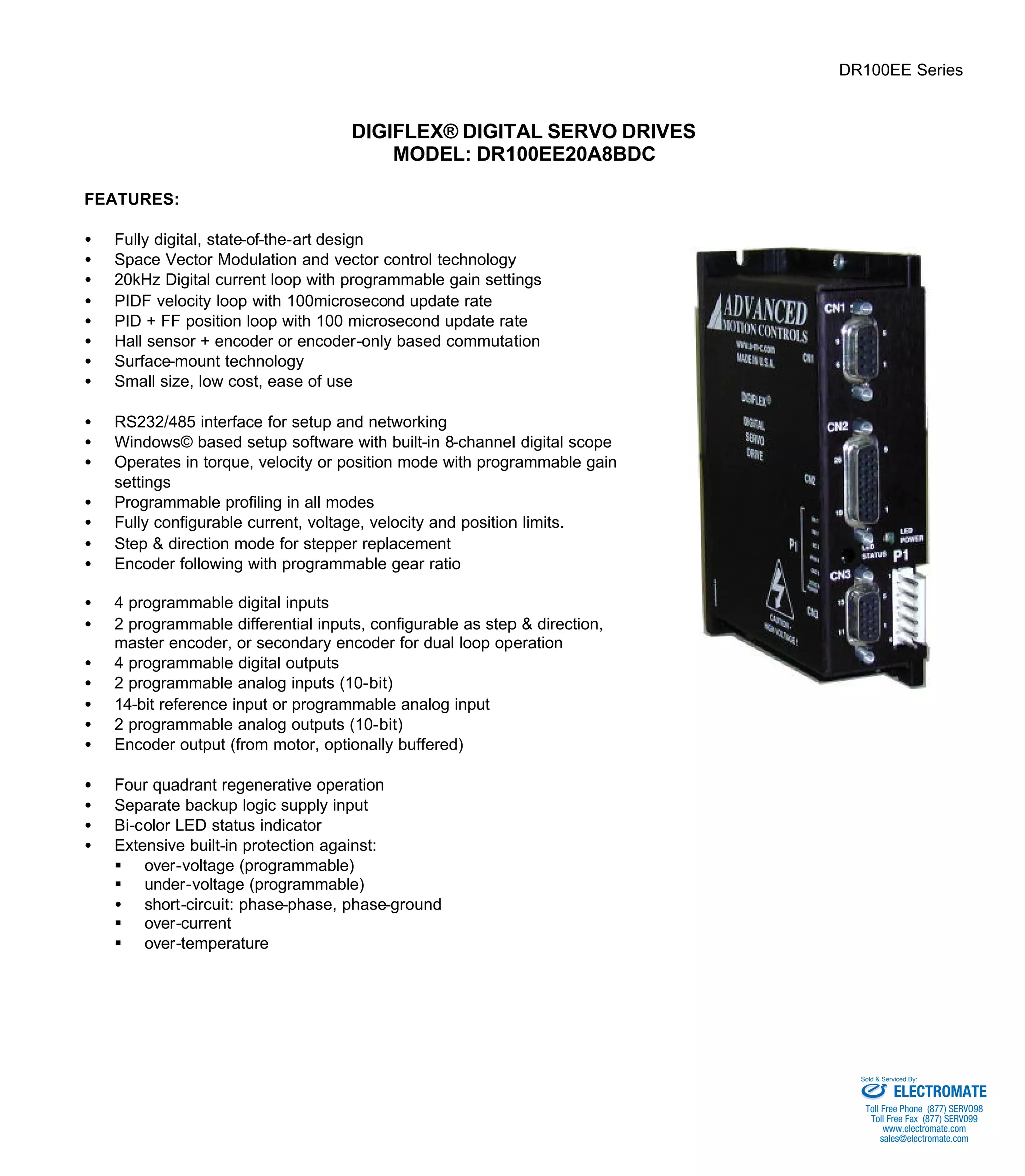
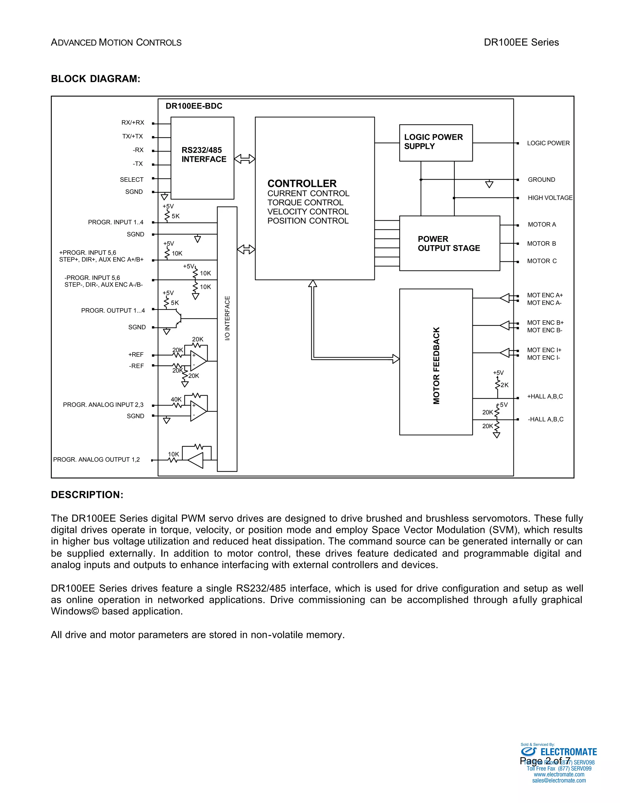
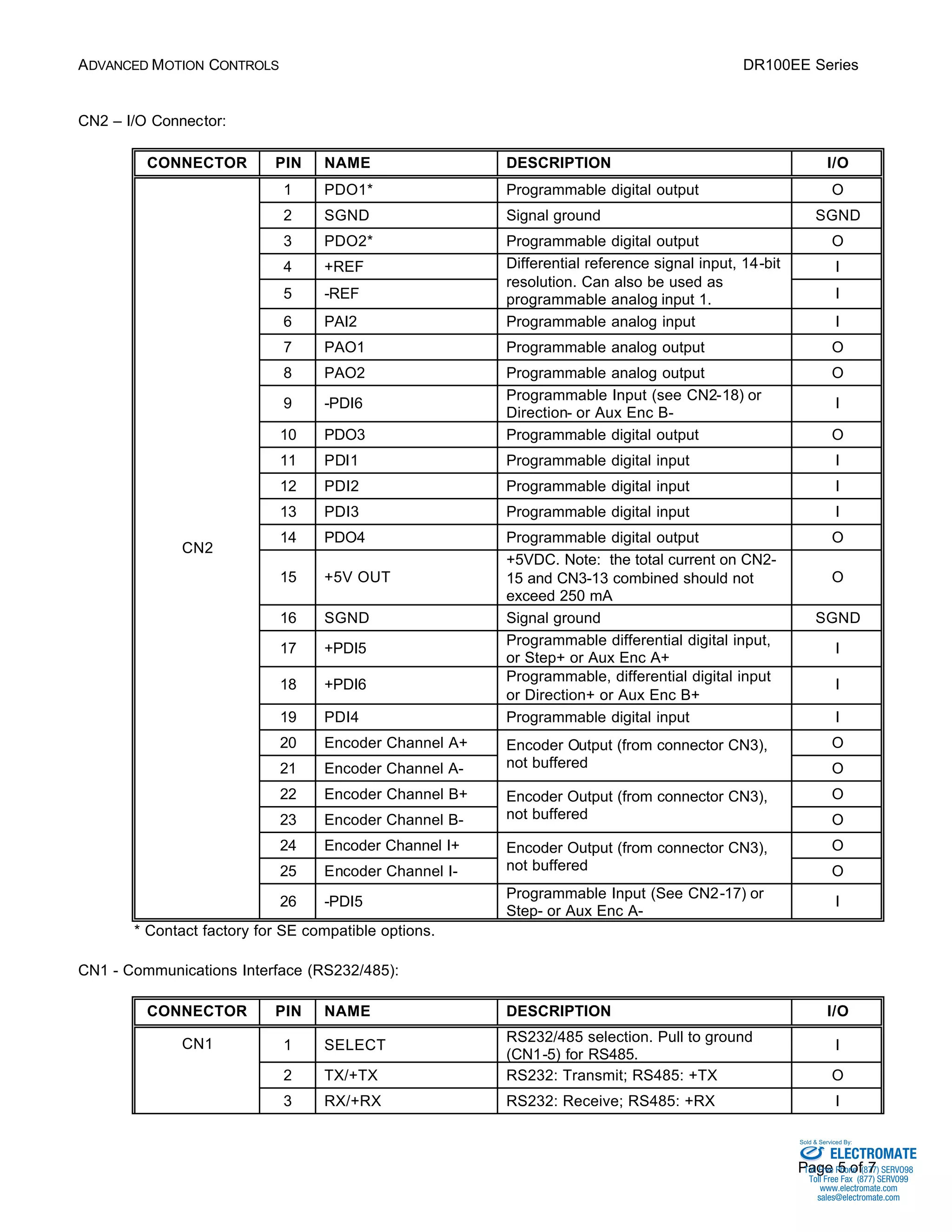

The DR100EE Series digital servo drives are fully digital PWM drives designed to control brushed and brushless servomotors. They operate in torque, velocity, or position mode using space vector modulation for high bus voltage utilization. The drives feature configurable digital and analog inputs and outputs for interfacing, and are set up using Windows-based software over an RS232/485 interface.


