Download to read offline
![1
A major revamp of the single-axis robot IS
series with improvements all around—from
preciseness, rigidity and payload capacity
to speed and acceleration/deceleration.
The positioning repeatability is twice as high as with
a similar conventional product.
Conventional product ISB series
• Standard
specification ±0.02 mm ➝ ±0.01 mm
• High-precision
specification ±0.01 mm ➝ ±0.005 mm
The SSPA series is an iron base type. It has more than twice the allowable moment in the Mc
direction in comparison to the old model of the same size.
Moment load (Mc direction) vs Angular displacement
[ Comparison between the large iron base type (SSPA-LXM) and the old model ]
• The same payload and Mc-direction rigidity are achieved at a cross-section area of just 60%
that of a conventional product of an extra-large type (ISA-WXM).
Comparison with conventional product of same payload and Mc-direction rigidity
NEW Iron-base type SSPA-LXM Conventional product
Mc
155
90
198
120
Compact size
with a cross-section
area of
just 60%
Extra-large type
ISA-WXM
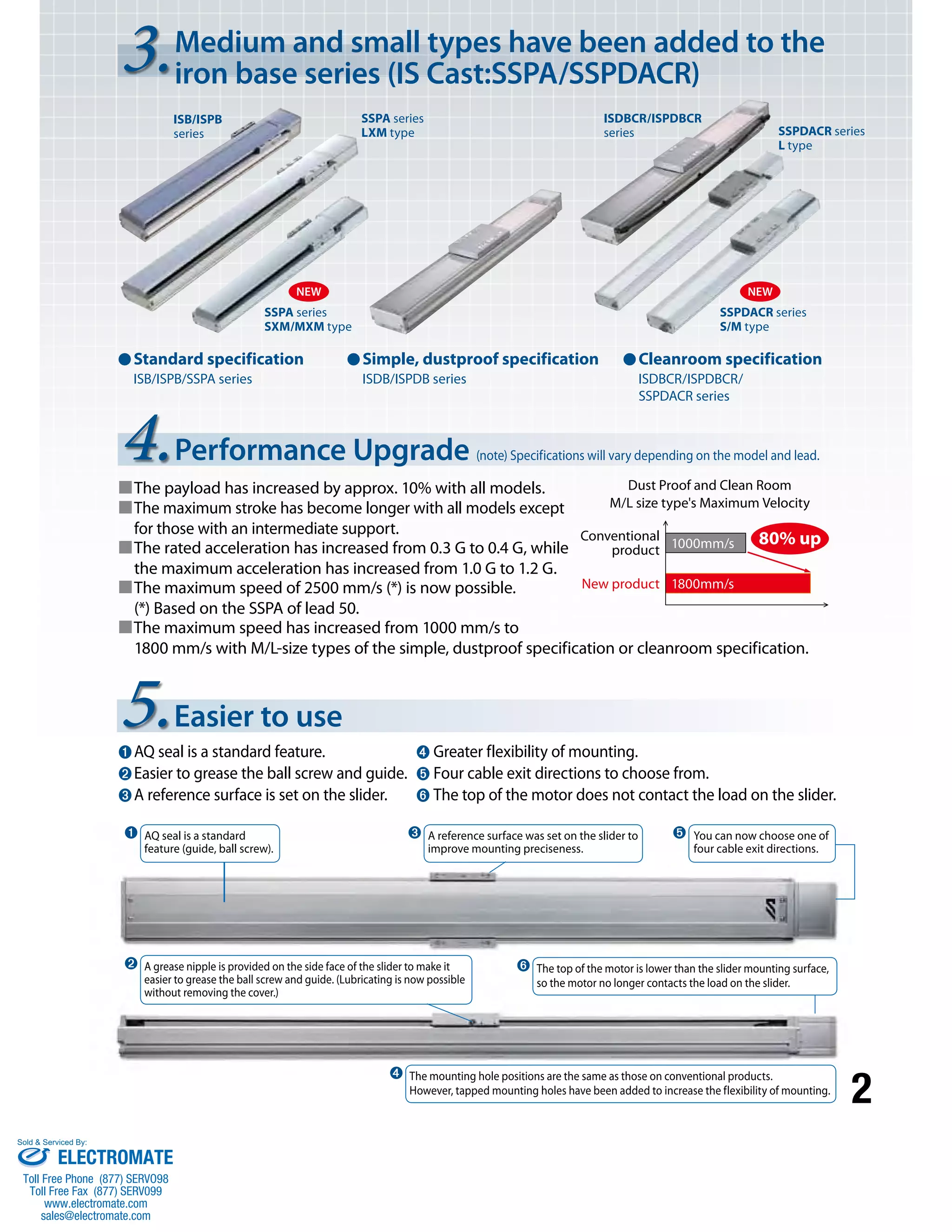
1. Improved preciseness
2. Improved rigidity
Due to an improved preciseness of the
guide, the dynamic straightness of the
slider is now
0.015 mm/m or less. (*)
* Based on the SSPA of high straightness,
precision specification.
Refer to P. 13 for details.
The long slider type has a longer slider compared to the standard model.
Compared to the old model of the same size, the allowable Mc is increased
by 10 to 20%. *Long slider type is only for the ISB/ISPB series.
Type Standard slider (L1) Long slider (L2)
Small S 90mm 110mm
Medium M 120mm 150mm
Large L 150mm 180mm
L1
L2
NEW
Standard slider type
Long slider type
Mc Direction
Allowable Mc is more than
twice than the old model.
0.07
0.06
0.05
0.04
0.03
0.02
0.01
0.00
0 200 400 600 800 1000
Moment load (N•m)
Angular displacement (deg)
SSPA-SXM
SSPA-MXM
SSPA-LXM
Angular displacement
Sold & Serviced By:
ELECTROMATE
Toll Free Phone (877) SERVO98
Toll Free Fax (877) SERV099
www.electromate.com
sales@electromate.com](https://image.slidesharecdn.com/iaiisbsspacatalog-141008213452-conversion-gate01/75/Iai-isb-sspa_catalog-2-2048.jpg)
![3
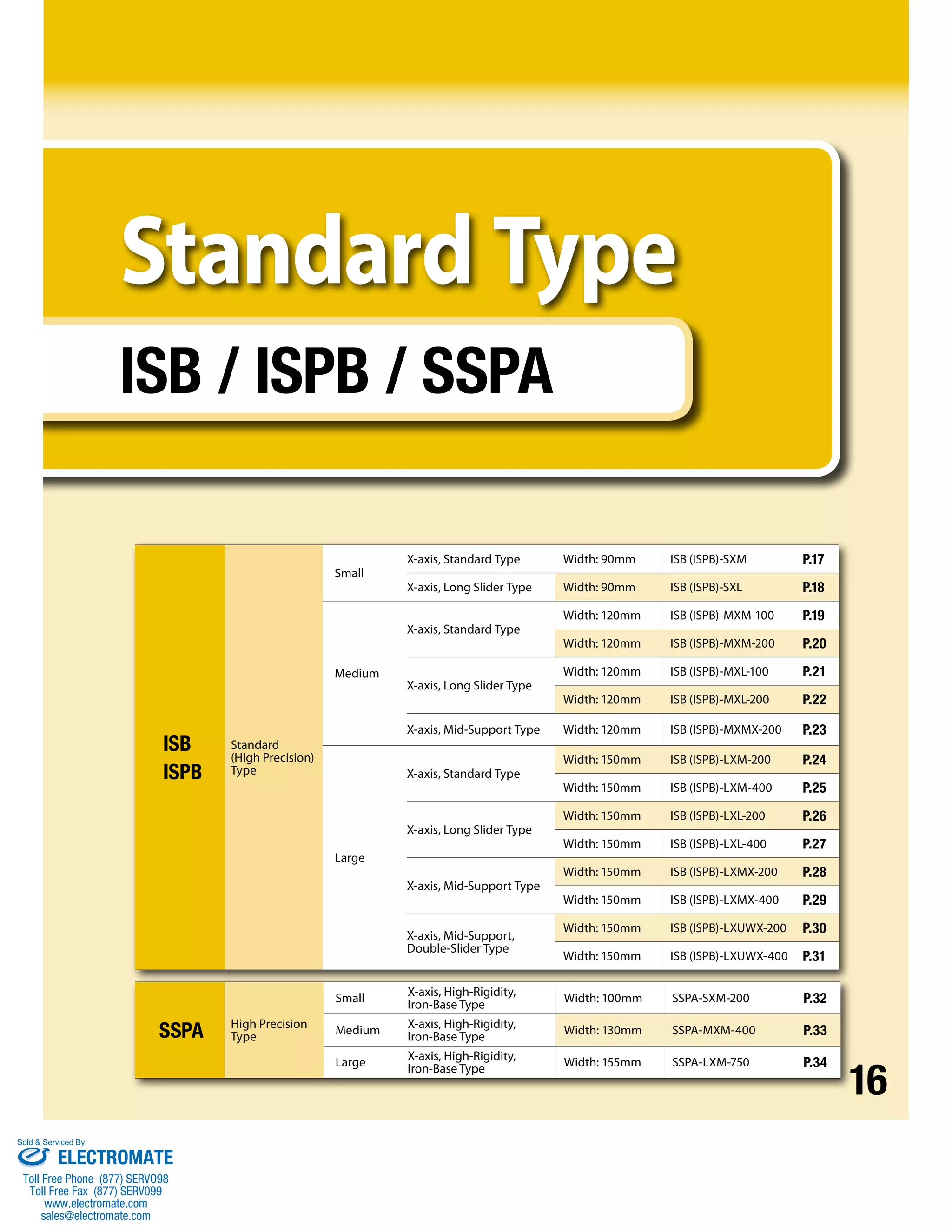
Product Specification List
Use
environment Base material Series name
[Positioning repeatability (mm)] Actuator size
Type Aluminum
Slider type
(slider length)
(Note 1)
base
ISB
(Standard specification)
[±0.01]
ISPB
(High precision
specification)
[±0.005]
[Actuator width: 90 mm]
Standard
[90mm] SXM
Long
[110mm] SXL
[Actuator width: 120 mm]
Standard
[120mm] MXM
Long
[150mm] MXL
With
mid-support
[120mm]
MXMX
[Actuator width: 150 mm]
Standard
[150mm] LXM
Long
[180mm] LXL
With
mid-support
[150mm]
LXMX
[Actuator width: 150 mm]
Double sliders
with mid-support
[250mm]
LXUWX
Small
Medium
Large
Large
Standard
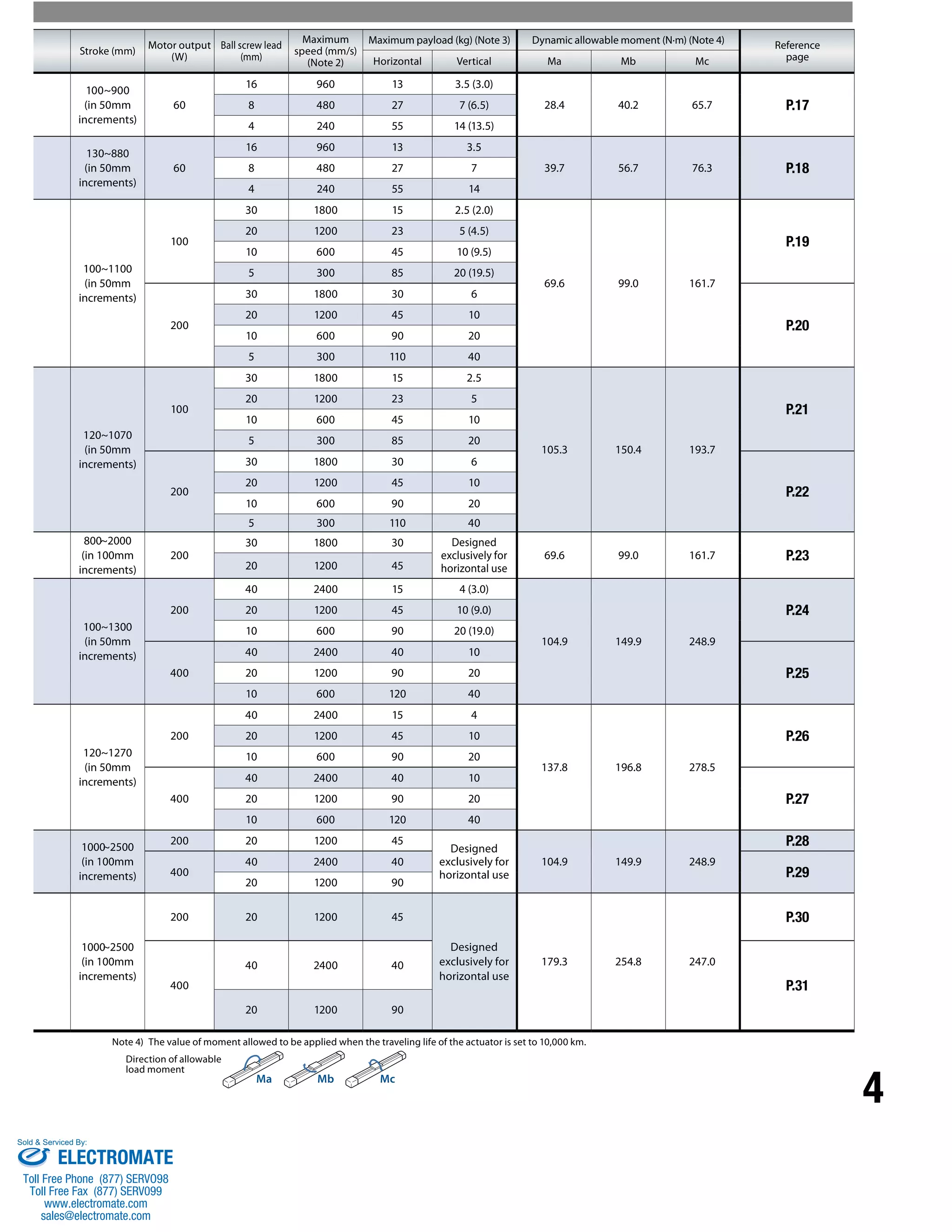
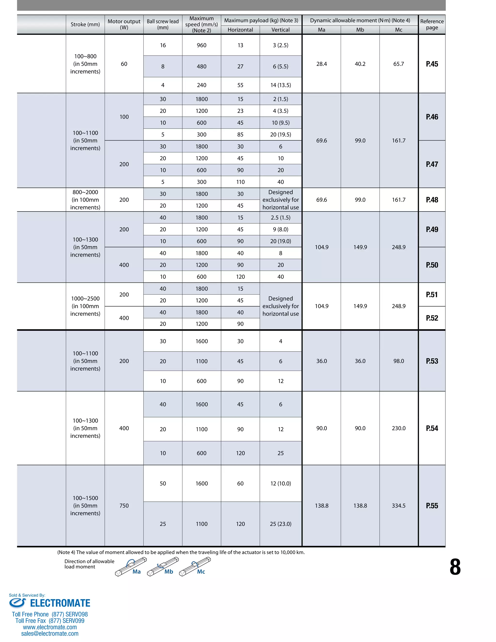
(Note 1) When the slider is longer, the dynamic allowable moment becomes more than that of the standard slider. When mid-support is provided, high-speed movement is
possible, even over a long stroke, because deflection of the ball screw can be suppressed.
(Note 2) If the stroke is short, the maximum speed may not be reached. When the stroke increases, the maximum speed will drop to prevent reaching a dangerous speed. For details,
refer to the page explaining the specifications of each model.
(Note 3) The maximum payload is the value when the actuator is operated at the rated acceleration. The maximum payload will drop if the acceleration is raised. For details, refer to
“Table of Payload by Acceleration” on P. 9. The values in ( ) are payloads when a guide with ball retention mechanism (RT) is used.
Sold & Serviced By:
ELECTROMATE
Toll Free Phone (877) SERVO98
Toll Free Fax (877) SERV099
www.electromate.com
sales@electromate.com](https://image.slidesharecdn.com/iaiisbsspacatalog-141008213452-conversion-gate01/75/Iai-isb-sspa_catalog-4-2048.jpg)
![5
Product Specification List
Use environment Base material Series name [Positioning repeatability
(mm)] Actuator size
Type Medium
Standard
Large
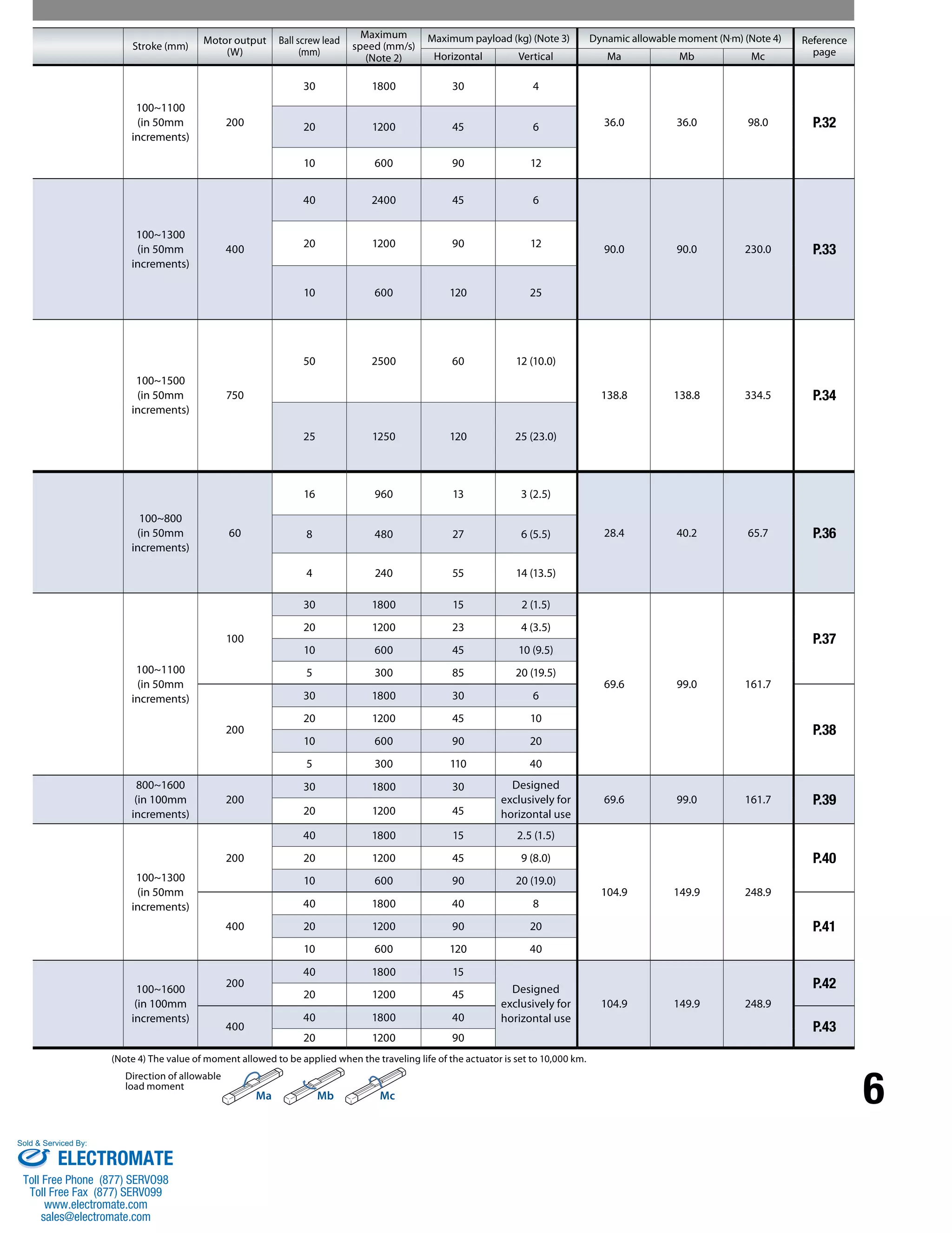
(Note 1) When a mid-support is provided, high-speed movement is possible, even over a long stroke, because deflection of the ball screw can be suppressed.
(Note 2) If the stroke is short, the maximum speed may not be reached. When the stroke increases, the maximum speed will drop to prevent reaching a dangerous speed.
For details, refer to the page explaining the specifications of each model.
(Note 3) The maximum payload is the value when the actuator is operated at the rated acceleration. The maximum payload will drop if the acceleration is raised. For details, refer to
“Table of Payload by Acceleration” on P. 9. The values in ( ) are payloads when a guide with ball retention mechanism (RT) is used.
Slider type
(slider length)
(Note 1)
Iron
base
SSPA
(High precision specification)
[±0.005]
[Actuator width:100mm]
Standard
(90mm) SXM
[Actuator width:130mm]
Standard
(120mm) MXM
[Actuator width:155mm]
Standard
(150mm) LXM
Simple, dustproof
Aluminum
base
ISDB
(Standard specification)
[±0.01]
ISPDB
(High precision specification)
[±0.005]
[Actuator width:90mm]
Standard
(154mm) S
[Actuator width:120mm]
Standard
(194mm) M
With
mid-support
(194mm)
MX
[Actuator width:150mm]
Standard
(224mm) L
With
mid-support
(224mm)
LX
NEW
NEW
Small
Small
Medium
Large
Sold & Serviced By:
ELECTROMATE
Toll Free Phone (877) SERVO98
Toll Free Fax (877) SERV099
www.electromate.com
sales@electromate.com](https://image.slidesharecdn.com/iaiisbsspacatalog-141008213452-conversion-gate01/75/Iai-isb-sspa_catalog-6-2048.jpg)
![7
Use
environment Base material Series name [Positioning
repeatability (mm)] Actuator size
Type Cleanroom
Slider type
(slider length)
(Note 1)
Aluminum
base
ISDBCR
(Standard specification)
[±0.01]
ISPDBCR
(High precision specification)
[±0.005]
[Actuator width: 90mm]
Standard
(154mm) S
[Actuator width:120mm]
Standard
(194mm) M
With
mid-support
(192mm)
MX
[Actuator width:150mm]
Standard
(224mm) L
With
mid-support
(220mm)
LX
Iron
base
SSPDACR
(High precision specification)
[±0.005]
[Actuator width:100mm]
Standard
(160mm) S
[Actuator width:130mm]
Standard
(200mm) M
[Actuator width:155mm]
Standard
(230mm) L
NEW
NEW
Product Specification List
Small
Medium
Large
Small
Medium
Large
(Note 1) When a mid-support is provided, high-speed movement is possible, even over a long stroke, because deflection of the ball screw can be suppressed.
(Note 2) If the stroke is short, the maximum speed may not be reached. When the stroke increases, the maximum speed will drop to prevent reaching a dangerous speed.
For details, refer to the page explaining the specifications of each model.
(Note 3) The maximum payload is the value when the actuator is operated at the rated acceleration. The maximum payload will drop if the acceleration is raised. For details, refer to
“Table of Payload by Acceleration” on P. 9. The values in ( ) are payloads when a guide with ball retention mechanism (RT) is used.
Sold & Serviced By:
ELECTROMATE
Toll Free Phone (877) SERVO98
Toll Free Fax (877) SERV099
www.electromate.com
sales@electromate.com](https://image.slidesharecdn.com/iaiisbsspacatalog-141008213452-conversion-gate01/75/Iai-isb-sspa_catalog-8-2048.jpg)
![13
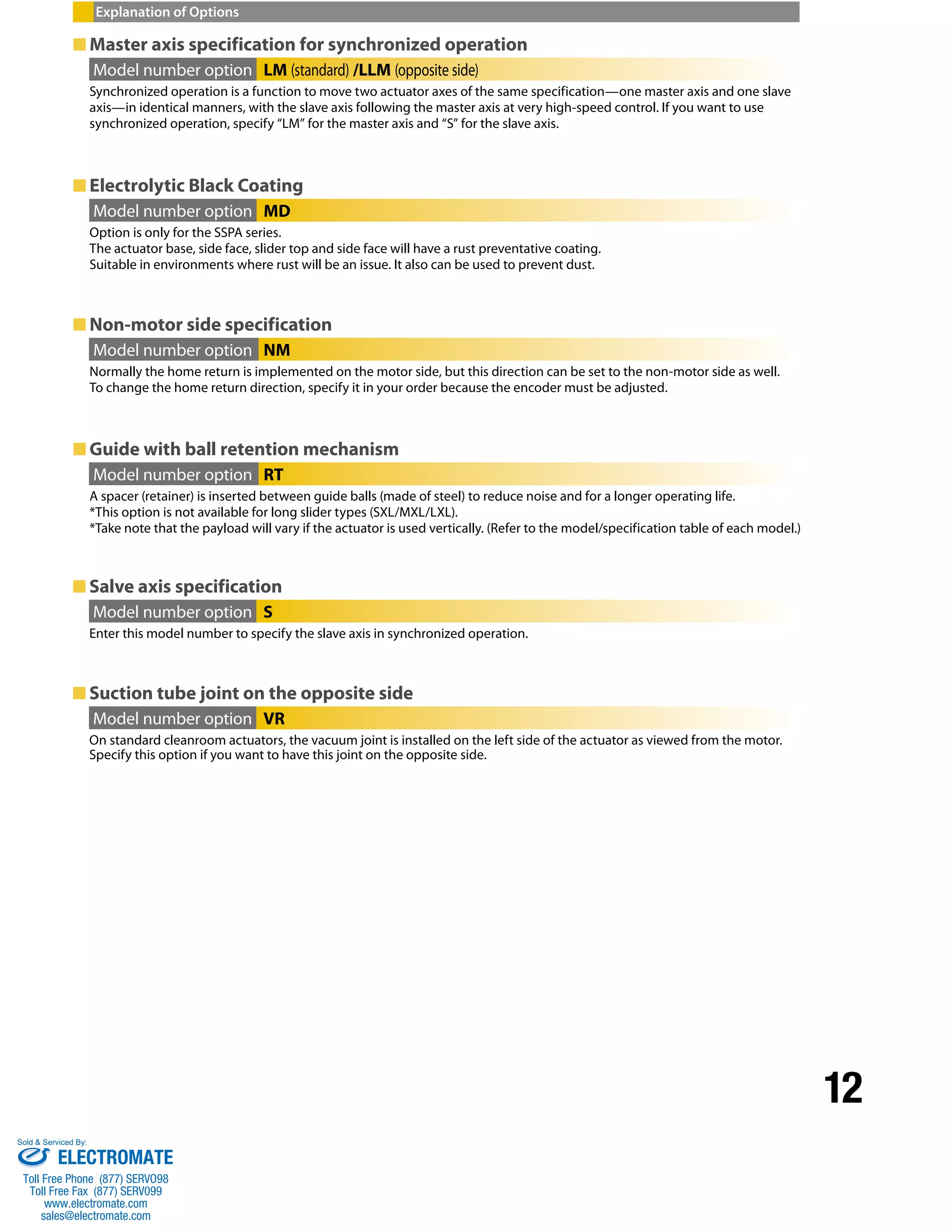
Explanation of Options
■High straightness, precision specification
Model number option ST
This specification represents a precision actuator of high traveling preciseness in terms of dynamic parallelism (horizontal/
vertical) and dynamic straightness (horizontal/vertical) of the slider.
The running parallelism and squareness is based on stroke length. The values shown in the chart below is per 1m.
For calculations based on the stroke length, please use the Aluminum Base and Iron Base Calculation Examples below.
Aluminum base Iron base
[ ] [ ]
[ ] [ ]
Parallelism during motion 0.03mm/1m (parallelism/meter) x 1.5m (stroke) = 0.045mm
Squareness during motion 0.02mm/1m (squareness/meter) x 1.5m (stroke) = 0.03mm
Base reference surface
Aluminum Base and Iron Base Calculation Examples.
① Aluminum Base ISB/ISPB/ISDB/ISPDB/ISDBCR/ISPDBCR series
Straight gauge
Reference point Reference point
Base reference surface
Precision surface plate
Straightness
Parallelism
Line of representative values
Deviation
Slider travel
Measured value
Ex) When the stroke is 1500mm
1 Dynamic parallelism (horizontal/vertical)
① Parallelism of the base reference surface and the
slider motion (horizontal)
With the base affixed on a precision surface plate, an
indicator on the slider is caused to contact a straight gauge
placed in parallel with two points at both ends of the base
reference surface, and then the actuator is moved over the
entire stroke. The parallelism of the base reference surface
and the slider motion represents the maximum difference
between the measured values.
② Parallelism of the base mounting surface and
the slider motion (vertical)
With the base affixed on a precision surface plate, an
indicator on the slider is caused to contact the surface
plate, and then the actuator is moved over the entire
stroke. The parallelism of the base mounting surface and
the slider motion represents the maximum difference
between the measured values.
*Round up to the 3rd decimal place
② Iron Base SSPA/SSPDACR Series
Ex) When the stroke is 900mm
Parallelism during motion 0.03mm/1m (parallelism/meter) x 0.9m (stroke) = 0.027mm
Squareness during motion 0.015mm/1m (squareness/meter) x 0.9m (stroke) = 0.014mm
*Round up to the 3rd decimal place
2 Dynamic straightness (horizontal/vertical)
With the base affixed on a precision surface plate, an
indicator on the slider is caused to contact a straight
gauge placed in parallel with two points at both ends
of the base reference surface, and then the actuator is
moved over the entire stroke. The parallelism of the base
reference surface and the slider motion represents the
maximum difference between the measured values.
(*)The method of preciseness measurement conforms to IAI’s inspection standard.
Without high straightness,
precision specification
With high straightness, precision
specification (*)
Without high straightness,
precision specification
With high straightness, precision
specification (*)
1 Dynamic parallelism
[mm/m or less] 0.05
0.03
However, if the stroke is less
than or equal to 500mm, the
squareness will be 0.015mm.
0.05
0.03
However, if the stroke is less
than or equal to 500mm, the
squareness will be 0.015mm.
2 Dynamic straightness
[mm/m or less] 0.05
0.020
However, if the stroke is less
than or equal to 500mm, the
squareness will be 0.01mm.
0.05
0.015
However, if the stroke is less
than or equal to 500mm, the
squareness will be 0.008 mm.
Sold & Serviced By:
ELECTROMATE
Toll Free Phone (877) SERVO98
Toll Free Fax (877) SERV099
www.electromate.com
sales@electromate.com](https://image.slidesharecdn.com/iaiisbsspacatalog-141008213452-conversion-gate01/75/Iai-isb-sspa_catalog-14-2048.jpg)
![14
[Duty]
The duty represents the utilization ratio of the actuator (time during which the
actuator is operating in each cycle). Since an estimation for applicable duty
varies depending on the operating conditions (transferring mass, acceleration/
deceleration, etc.), calculate the load factor LF and acceleration/deceleration
time ratio tod using the formula on the right and read off an appropriate duty
from the graph.
■ How to calculate duty
➊ Calculate the load factor LF using the formula below:
Duty = Operating time (%)
Operating time + Stopped time
Load factor: LF=
M x α
Mr x αr (%)
•Payload at rated acceleration: Mr •Actual transferring mass: M
•Rated acceleration/deceleration: αr •Actual acceleration/deceleration: α
(Note) Refer to the model number/specification table of each model for the payload at rated acceleration and rated acceleration/
deceleration.
➋ Calculate the acceleration/deceleration time ratio tod using the formula below:
➌ Read off the estimated duty from the calculated load factor LF and the acceleration/deceleration time ratio tod.
Example. When the load factor LF is 80% and the acceleration/deceleration time ratio tod is 80%, an estimation for duty is approx. 75%.
100
80
60
40
20
0
Estimated duty (%)
0 20 40 60 80 100
Acceleration/deceleration time ratio tod (%)
LF = Less than 50%
LF = 60%
Approx. 75% LF = 70%
LF = 80%
LF = 90%
LF = 100%
[Dynamic allowable moment and overhang load length]
The dynamic allowable moment, calculated from the traveling life of the guide, is the maximum offset load that can be applied to the slider.
The traveling life will decrease when the allowable value is exceeded, so use an auxiliary guide, etc., if it is used within the allowable value
or the allowable value is exceeded. The overhang load length represents the maximum length that can overhang from the slider when the
requirement for dynamic allowable moment is met. Take note that if the specified overhang load length is exceeded, vibration, etc., may
occur.
Mb direction Ma direction
Mb, Mc directions
L
L
Mc direction Ma direction
Direction of the dynamic allowable moment Direction of the allowable overhang length
Cautions for Use
Acceleration/deceleration= Acceleration time + Deceleration time
time ratio t od Operating time (%)
Acceleration= Speed (mm/s) (sec)
time Acceleration (mm/s2)
Deceleration= Speed (mm/s) (sec)
time Deceleration (mm/s2)
Acceleration (mm/s2) = Acceleration (G) x 9,800 mm/s2 Deceleration (mm/s2) = Deceleration (G) x 9,800 mm/s2
Sold & Serviced By:
ELECTROMATE
Toll Free Phone (877) SERVO98
Toll Free Fax (877) SERV099
www.electromate.com
sales@electromate.com](https://image.slidesharecdn.com/iaiisbsspacatalog-141008213452-conversion-gate01/75/Iai-isb-sspa_catalog-15-2048.jpg)
![15
Cautions for Use
[Mounting]
Check the mounting orientation of each model in the table below.
Mounting orientation
: Installable —: Not installable
Horizontal, flat Vertical Note 1 Side-mounted Ceiling-mounted
Series Type
ISB
ISPB
SXM, SXL,
MXM, MXL,
LXM, LXL
Note 2 Note 3
MXMX,
LXMX, LXUWX — — —
SSPA SXM, MXM, LXM Note 2 Note 3
ISDB
ISPDB
ISDBCR
ISPDBCR
S, M, L Note 4 Note 4
MX, LX —
—
—
SSPDACR S, M, L — —
Note 1 When installing the actuator vertically, bring the motor to the top whenever possible. If the actuator is mounted with the motor
at the bottom, problems won’t occur during normal operation, but if the actuator is stopped for a prolonged period of time, grease
may separate depending on the ambient environment (especially when the ambient temperature is high), in which case base oil
may flow into the motor unit and could cause problems on rare occasions.
Note 2 The base oil may separate from the grease and can flow out from the opening on the side of the actuator. Also, foreign debris is
able to fall into the actuator through the opening on the side of it.
Note 3 When the actuator with screw cover is ceiling mounted, the screw cover can bend and it may interfere with the work part. If the
stroke of the ISB exceeds 600mm, or if the stroke of the SSPA exceeds 800mm, please attach the work part by an offset distance A
away from the slider.
The table below shows the distance A from the slider
seating surface.
Series Stroke Distance A
ISB
ISPB
600mm or greater but
less than 1000mm
5mm or
greater
1000mm or greater but
less than 1300mm
10mm or
greater
SSPA 800 mm or greater but
less than 1500mm
5mm or
greater
A
Note 4 When a 400mm stroke actuator with a stainless sheet is side mounted or ceiling mounted, the stainless sheet may be subjected to
flexure and can be misaligned. If continued to be used in those conditions, the stainless sheet can be damaged. Please maintain
daily and use the manual as a reference for the maintenance procedure of the stainless sheet.
Sold & Serviced By:
ELECTROMATE
Toll Free Phone (877) SERVO98
Toll Free Fax (877) SERV099
www.electromate.com
sales@electromate.com](https://image.slidesharecdn.com/iaiisbsspacatalog-141008213452-conversion-gate01/75/Iai-isb-sspa_catalog-16-2048.jpg)
![ISB-SXM
ISPB-SXM
SXM 60
Series Type Encoder type Motor type Lead Stroke Applicable controller Cable length Options
ISB: Standard
ISPB: High precision
Model
Specification
Items
* Refer to P. 10 for the details of items comprising the model number.
Name Model
CAD drawings
are available for
download from
our website.
2D
CAD
17 ISB-SXM/ISPB-SXM
Single-axis robot/Small, X-axis, standard slider type/Actuator width: 90mm/60W
Straight shape
Single-axis robot/Small, X-axis, standard slider type/Actuator width: 90mm/60W
Straight shape High precision specification
A: Absolute
specification
I: Incremental
specification
1.5 4.5
100
81
100: 100mm
900: 900mm
(in 50mm increments)
8
90
60: 60W 16 : 16mm
23
ME SE
50
8 : 8mm
4 : 4mm
+0.012
0
20
10
5
A
T1: XSEL-J/K
T2: SCON
SSEL
XSEL-P/Q
N : None
S : 3m
M : 5m
X: Specified length
H x 200 pitch
Refer to the options
table below.
50 90
90
2-ø6H7, depth 10
4-M6, depth 18
38 14 69
5
70
45
10
90
Home
10
14 18
35
Cable exit from the right
(model number: A3S)
Cable exit from the left
(model number: A1S)
77
80
K J
L
2-M3, depth 6
(same on the opposite side)
Grease nipple (same on the opposite side)
D 50
1 59 2
GF
B
specification
specification
104 (standard + 35)
(with brake)
84
7.3
4.3
62
15 15
5
6 6
‡11
‡7
Detail view of base mounting hole, T slot
Slider reference surface
Base reference surface
50
Base reference surface 7 (from reference surface)
C x 200 pitch
E-ø7 hole, ø11 counterbored (from opposite side)
Cable exit from the rear right
(model number: A3E)
Cable exit from the rear left
(model number: A1E)
Cable joint
connector *1
Cable length
(300)
ME*2
(without
brake)
2-ø6H7, depth10
*1
Connect the
motor cable
and encoder
cable. Refer
to P. 57 for
the cables.
2-ø6H7, depth 10
Washer-assembled screw M3
(for FG, 2 locations)
P-M6, depth 16
Oblong hole,
depth 10
T slot
84
70
6
5
90
14
90±0.02 70±0.02
7
17
42
Model Number/Specification
Option Common Specifications
Applicable Controller Specifications
*1.0G=9800mm/sec2
* In the above model numbers, indicates the encoder type, indicates the stroke, indicates the applicable controller, indicates the cable length, and indicates the option(s).
** If the guide with ball retention mechanism (RT) is used, the vertical payload decreases by 0.5kg. (Please also refer to P.9).
Positioning repeatability (Note 2) ±0.01mm [±0.005mm]
Drive method (Note 3) Ball screw 012mm, rolled C10 [equivalent to rolled C5]
Lost Motion (Note 4) 0.05mm [0.02mm] max.
Dynamic allowable load moment (Note 5) Ma: 28.4N•m Mb: 40.2N•m Mc: 65.7N•m
Overhang load length Ma direction: 450mm max. Mb, Mc directions: 450mm max.
Dynamic straightness (Note 6) 0.02mm/m max.
Base Material: Aluminum, with white alumite treatment
Applicable controller T1: XSEL-J/K T2: XSEL-P/Q, SSEL, SCON
Cable length (Note 7) N: None, S: 3m, M: 5m, X: Specified length
Ambient operating temperature/humidity 0 to 40°C, 85%RH max. (non-condensing)
■ Dimensions, Mass and Maximum Speed by Stroke
*If the brake is equipped, the mass increases by 0.3 kg. *The maximum speed (mm/s) varies depending on the stroke.
Stroke 100 150 200 250 300 350 400 450 500 550 600 650 700 750 800 850 900
L without brake 344 394 444 494 544 594 644 694 744 794 844 894 944 994 1044 1094 1144
with brake 379 429 479 529 579 629 679 729 779 829 879 929 979 1029 1079 1129 1179
A 100 150 200 250 300 350 400 450 500 550 600 650 700 750 800 850 900
B 251 301 351 401 451 501 551 601 651 701 751 801 851 901 951 1001 1051
C 0 0 0 1 1 1 1 2 2 2 2 3 3 3 3 4 4
D 151 201 251 101 151 201 251 101 151 201 251 101 151 201 251 101 151
E 4 4 4 6 6 6 6 8 8 8 8 10 10 10 10 12 12
F 151 201 251 301 351 401 451 501 551 601 651 701 751 801 851 901 951
G 131 131 181 231 281 331 381 431 481 531 581 631 681 731 781 831 881
H 0 0 0 0 0 0 1 1 1 1 2 2 2 2 3 3 3
J 56 56 106 156 206 256 106 156 206 256 106 156 206 256 106 156 206
K 0 50 50 50 50 50 50 50 50 50 50 50 50 50 50 50 50
P 8 10 10 10 10 10 12 12 12 12 14 14 14 14 16 16 16
Mass (kg) 3.0 3.4 3.8 4.2 4.5 4.9 5.2 5.6 5.9 6.3 6.6 7.0 7.3 7.7 8.0 8.4 8.7
Maximum
speed
(mm/s)
Lead 16 960 655 515 415
Lead 8 480 330 260 210
Lead 4 240 165 130 100
Diagram
*2
During the home
return, the slider
moves to the ME, so
pay attention not to
let the slider hit
surrounding parts.
* Take note that to change the home direction, the
actuator must be returned to us for adjustment.
Applicable
Controller
Maximum number
of controlled axes
Connectable
encoder type
Operating
method
Power-supply
voltage
Reference
page
X-SEL-P/Q 6 axes
Absolute/
incremental
Program
Single/three-phase
200 VAC ➔P56
X-SEL-J/K 4 axes
Single-phase
100/200 VAC
➔P56
SSEL 2 axes ➔P56
SCON 1 axis Positioner pulse
train control ➔P56
(Note 1) Refer to P. 9 for the relationship of acceleration and payload.
(Notes 2, 3, 4) The values in [ ] apply to the ISPB series. Other specification
values apply commonly to the ISB and ISPB.
(Note 5) When the traveling life is 10,000km.
(Note 6) The value of dynamic straightness is when the high straightness,
precision specification (option) is specified.
(Note 7) The maximum cable length is 30m. Specify a desired length in
meters.
(Example. X08 = 8m)
Model number Encoder type
Motor
output
(W)
Lead
(mm)
Stroke in
50mm
increments
(mm)
Speed
(mm/s)
Acceleration (Note 1) Payload (Note 1)
Rated
thrust (N)
Horizontal (G) Vertical (G) Horizontal (kg) Vertical (kg)**
Rated Maximum Rated Maximum Rated
acceleration
Maximum
acceleration
Rated
acceleration
Maximum
acceleration
ISB[ISPB]-SXM- -60-16- - - -
Absolute
Incremental 60
16
100~900
1~960 0.4 1.2 0.4 0.8 13 3.5 3.5 2 53.1
ISB[ISPB]-SXM- -60-8- - - - 8 1~480 0.4 0.7 0.4 0.6 27 12 7 5 106.1
ISB[ISPB]-SXM- -60-4- - - - 4 1~240 0.2 0.5 0.2 0.4 55 30 14 12 212.3
SE: Stroke End
ME: Mechanical End
number
Reference
page Name Model
number
Reference
page
Cable exit from the left A1S ➔P11 Home limit switch L ➔P11
Cable exit from the rear left A1E ➔P11 Home limit switch on the opposite side LL ➔P11
Cable exit from the right A3S ➔P11 Master axis specification LM ➔P12
Cable exit from the rear right A3E ➔P11 Master axis specification (sensor on the opposite side) LLM ➔P12
AQ seal (standard feature) AQ ➔P11 Non-motor side specification NM ➔P12
Brake B ➔P11 Guide with ball retention mechanism RT ➔P12
Creep sensor C ➔P11 Slave axis specification S ➔P12
Creep sensor on the opposite side CL ➔P11 High straightness, precision specification ST ➔P13
Sold & Serviced By:
ELECTROMATE
Toll Free Phone (877) SERVO98
Toll Free Fax (877) SERV099
www.electromate.com
sales@electromate.com](https://image.slidesharecdn.com/iaiisbsspacatalog-141008213452-conversion-gate01/75/Iai-isb-sspa_catalog-18-2048.jpg)
![Series Type Encoder type Motor type Lead Stroke Applicable controller Cable length Options
Acceleration (Note 1) Payload (Note 1)
Cable exit from the right
(model number: A3S)
Cable exit from the left
(model number: A1S)
Washer-assembled screw M3
(for FG, 2 locations)
Cable exit from the rear right
(model number: A3E)
*1
Connect the
motor cable
and encoder
cable. Refer
to P. 57 for
the cables.
*2
During the home
return, the slider
moves to the ME, so
pay attention not to
let the slider hit
surrounding parts.
*If the brake is equipped, the mass increases by 0.3 kg. *The maximum speed (mm/s) varies depending on the stroke.
18 ISB-SXL/ISPB-SXL
Model number Encoder type
7.3
4.3
1.5 4.5
11
5
7
15
6
Detail view of base mounting hole, T slot
100
81
84
90
Slider reference surface
T slot
62
15
6
Base reference surface
104 (standard + 35)
84
70
50
(with brake) Base reference surface
7
17
42
Lead
(mm)
8
Motor
output
(W)
6 +0.012
0
ME SE
20 50
50
50
20 20
ME*2
14 69
2-ø6H7, depth 10
110
100
70
Speed
(mm/s)
H x 200 pitch 90 P-M6, depth 16
50
Stroke in
50mm
increments
(mm)
J
D
Oblong hole,
depth 10
GF
B
70±0.02
7 (from reference surface)
C x 200 pitch
E-ø7 hole, ø11 counterbored (from opposite side)
2-ø6H7, depth 10
80
35
10 23
5
L
5 5
55
A
2-M3, depth 6
(same on the opposite side)
Grease nipple (same on the opposite side)
(without
brake)
110 38
Home
5
14 28
14
90
90±0.02 5
2-ø6H7, depth 10
8-M6, depth 18
Cable joint
connector *1
Cable length
(300)
77
1 59 2
Cable exit from the rear left
(model number: A1E)
Model Number/Specification
Option Common Specifications
Diagram
SE: Stroke End
ME: Mechanical End
■ Dimensions, Mass and Maximum Speed by Stroke
Applicable Controller Specifications
*1.0G=9800mm/sec2
*In the above model numbers, indicates the encoder type, indicates the stroke, indicates the applicable controller, indicates the cable length, and indicates the option(s).
Rated
thrust (N)
Horizontal (G) Vertical (G) Horizontal (kg) Vertical (kg)
Rated Maximum Rated Maximum Rated
acceleration
Maximum
acceleration
Rated
acceleration
Maximum
acceleration
ISB[ISPB]-SXL- -60-16- - - -
Absolute
Incremental 60
16
130~880
1~960 0.4 1.2 0.4 0.8 13 3.5 3.5 2 53.1
ISB[ISPB]-SXL- -60-8- - - - 8 1~480 0.4 0.7 0.4 0.6 27 12 7 5 106.1
ISB[ISPB]-SXL- -60-4- - - - 4 1~240 0.2 0.5 0.2 0.4 55 30 14 12 212.3
Name Model
number
Reference
page Name Model
number
Reference
page
Cable exit from the left A1S ➔P11 Home limit switch L ➔P11
Cable exit from the rear left A1E ➔P11 Home limit switch on the opposite side LL ➔P11
Cable exit from the right A3S ➔P11 Master axis specification LM ➔P12
Cable exit from the rear right A3E ➔P11 Master axis specification (sensor on the opposite side) LLM ➔P12
AQ seal (standard feature) AQ ➔P11 Non-motor side specification NM ➔P12
Brake B ➔P11 Slave axis specification S ➔P12
Creep sensor C ➔P11 High straightness, precision specification ST ➔P13
Creep sensor on the opposite side CL ➔P11
Positioning repeatability (Note 2) ±0.01mm [±0.005mm]
Drive method (Note 3) Ball screw 012mm, rolled C10 [equivalent to rolled C5]
Lost Motion (Note 4) 0.05mm [0.02mm] max.
Dynamic allowable load moment (Note 5) Ma: 39.7N•m Mb: 56.7N•m Mc: 76.3N•m
Overhang load length Ma direction: 550mm max. Mb, Mc directions: 550mm max.
Dynamic straightness (Note 6) 0.02mm/m max.
Base Material: Aluminum, with white alumite treatment
Applicable controller T1: XSEL-J/K T2: XSEL-P/Q, SSEL, SCON
Cable length (Note 7) N: None, S: 3m, M: 5m, X: Specified length
Ambient operating temperature/humidity 0 to 40°C, 85%RH max. (non-condensing)
Stroke 130 180 230 280 330 380 430 480 530 580 630 680 730 780 830 880
L without brake 394 444 494 544 594 644 694 744 794 844 894 944 994 1044 1094 1144
with brake 429 479 529 579 629 679 729 779 829 879 929 979 1029 1079 1129 1179
A 130 180 230 280 330 380 430 480 530 580 630 680 730 780 830 880
B 301 351 401 451 501 551 601 651 701 751 801 851 901 951 1001 1051
C 0 0 1 1 1 1 2 2 2 2 3 3 3 3 4 4
D 201 251 101 151 201 251 101 151 201 251 101 151 201 251 101 151
E 4 4 6 6 6 6 8 8 8 8 10 10 10 10 12 12
F 201 251 301 351 401 451 501 551 601 651 701 751 801 851 901 951
G 131 181 231 281 331 381 431 481 531 581 631 681 731 781 831 881
H 0 0 0 0 0 1 1 1 1 2 2 2 2 3 3 3
J 56 106 156 206 256 106 156 206 256 106 156 206 256 106 156 206
P 10 10 10 10 10 12 12 12 12 14 14 14 14 16 16 16
Mass (kg) 3.1 3.5 3.9 4.3 4.6 5.0 5.3 5.7 6.0 6.4 6.7 7.1 7.4 7.8 8.1 8.5
Maximum
speed
(mm/s)
Lead 16 960 655 515 415
Lead 8 480 330 260 210
Lead 4 240 165 130 100
(Note 1) Refer to P. 9 for the relationship of acceleration and payload.
(Notes 2, 3, 4) The values in [ ] apply to the ISPB series. Other specification
values apply commonly to the ISB and ISPB.
(Note 5) When the traveling life is 10,000km.
(Note 6) The value of dynamic straightness is when the high straightness,
precision specification (option) is specified.
(Note 7) The maximum cable length is 30m. Specify a desired length in
meters.
(Example. X08 = 8m)
Applicable
Controller
Maximum number
of controlled axes
Connectable
encoder type
Operating
method
Power-supply
voltage
Reference
page
X-SEL-P/Q 6 axes
Absolute/
incremental
Program
Single/three-phase
200 VAC ➔P56
X-SEL-J/K 4 axes
Single-phase
100/200 VAC
➔P56
SSEL 2 axes ➔P56
SCON 1 axis Positioner pulse
train control ➔P56
ISB-SXL
ISPB-SXL
Single-axis robot/Small, X-axis, long slider type/Actuator width: 90mm/60W
Straight shape
Single-axis robot/Small, X-axis, long slider type/Actuator width: 90mm/60W
Straight shape High precision specification
130: 130mm
880: 880mm
(in 50 mm increments)
ISB: Standard
specification
ISPB: High precision
specification
A: Absolute
specification
I: Incremental
specification
60: 60W 16 : 16mm
8 : 8mm
4 : 4mm
Model
Specification
Items
SXL 60
T1: XSEL-J/K
T2: SCON
SSEL
XSEL-P/Q
N : None
S : 3m
M : 5m
X: Specified length
Refer to the options
table below.
* Take note that to change the home direction, the
actuator must be returned to us for adjustment.
* Refer to P. 10 for the details of items comprising the model number.
Sold Serviced By:
ELECTROMATE
Toll Free Phone (877) SERVO98
Toll Free Fax (877) SERV099
www.electromate.com
sales@electromate.com](https://image.slidesharecdn.com/iaiisbsspacatalog-141008213452-conversion-gate01/75/Iai-isb-sspa_catalog-19-2048.jpg)
![Series Type Encoder type Motor type Lead Stroke Applicable controller Cable length Options
* Refer to P. 10 for the details of items comprising the model number.
Model Number/Specification
* In the above model numbers, indicates the encoder type, indicates the stroke, indicates the applicable controller, indicates the cable length, and indicates the option(s).
** If the guide with ball retention mechanism (RT) is used, the vertical payload decreases by 0.5kg. (Please also refer to P.9).
Option Common Specifications
Name Model
1.5 4.5
Slider reference surface
80
4.3
■ Dimensions, Mass and Maximum Speed by Stroke
ISB-MXM-100/ISPB-MXM-100 19
12 32
134
106
ME SE
120 20 50
50
+0.015
0
50 D
10
110
110
120
90
70
15 15
25 25
7
19
10
90
20 70
8
55
16
9
7.3
22
22
6
6
7
Base reference surface
Detail view of base
mounting hole, T slot
T slot
87 (standard + 24)
(with brake)
Base reference surface
Oblong hole,
depth 10
J
B
50
120
100
40
G
F
H x 200 pitch
10 (from reference surface)
C x 200 pitch
90±0.02
E-ø9 hole, ø16 counterbored (from opposite side)
2-ø8H7, depth10
*1
Connect the
motor cable
and encoder
cable. Refer
to P. 57 for
the cables.
K-M8, depth 20
2-ø8H7, depth 10
5
A
L
120
60
120
52
5
24 8
14 63
2-M3, depth 6
(same on the opposite side)
Home (without
brake)
Cable joint
connector *1
Cable length
(300)
120±0.02
ME*2
2-ø8H7, depth 10
4-M6, depth 18
4-M8, depth 18
Cable exit from the right
(model number: A3S)
Cable exit from the left
(model number: A1S)
Washer-assembled screw M3
(for FG, 2 locations)
102
Cable exit from the rear right
(model number: A3E)
Cable exit from the rear left
(model number: A1E)
1 77 2
Grease nipple (same on the opposite side)
*2
During the home
return, the slider
moves to the ME, so
pay attention not to
let the slider hit
surrounding parts.
Stroke 100 150 200 250 300 350 400 450 500 550 600 650 700 750 800 850 900 950 1000 1050 1100
L without brake 393 443 493 543 593 643 693 743 793 843 893 943 993 1043 1093 1143 1193 1243 1293 1343 1393
with brake 417 467 517 567 617 667 717 767 817 867 917 967 1017 1067 1117 1167 1217 1267 1317 1367 1417
A 100 150 200 250 300 350 400 450 500 550 600 650 700 750 800 850 900 950 1000 1050 1100
B 304 354 404 454 504 554 604 654 704 754 804 854 904 954 1004 1054 1104 1154 1204 1254 1304
C 0 0 1 1 1 1 2 2 2 2 3 3 3 3 4 4 4 4 5 5 5
D 204 254 104 154 204 254 104 154 204 254 104 154 204 254 104 154 204 254 104 154 204
E 4 4 6 6 6 6 8 8 8 8 10 10 10 10 12 12 12 12 14 14 14
F 204 254 304 354 404 454 504 554 604 654 704 754 804 854 904 954 1004 1054 1104 1154 1204
G 134 184 234 284 334 384 434 484 534 584 634 684 734 784 834 884 934 984 1034 1084 1134
H 0 0 0 0 0 0 1 1 1 1 2 2 2 2 3 3 3 3 4 4 4
J 24 74 124 174 224 274 124 174 224 274 124 174 224 274 124 174 224 274 124 174 224
K 10 10 10 10 10 10 12 12 12 12 14 14 14 14 16 16 16 16 18 18 18
Mass (kg) 6.0 6.6 7.2 7.9 8.5 9.2 9.8 10.4 11.0 11.7 12.3 13.0 13.6 14.2 14.8 15.5 16.1 16.8 17.4 18.1 18.7
Maximum
speed
(mm/s)
Lead 30 1800 1290 1045 860 690
Lead 20 1200 860 695 570 460
Lead 10 600 430 345 280 230
Lead 5 300 215 170 140 115
Diagram
Applicable Controller Specifications
*1.0G=9800mm/sec2
Model number Encoder
type
Motor
output
(W)
Lead
(mm)
Stroke in
50mm
increments
(mm)
Speed
(mm/s)
Acceleration (Note 1) Payload (Note 1)
Rated
thrust (N)
Horizontal (G) Vertical (G) Horizontal (kg) Vertical (kg)**
Rated Maximum Rated Maximum Rated
acceleration
Maximum
acceleration
Rated
acceleration
Maximum
acceleration
ISB[ISPB]-MXM- -100-30- - - -
Absolute
Incremental 100
30
100~1100
1~1800 0.4 1.2 0.4 1.2 15 3 2.5 1 56.6
ISB[ISPB]-MXM- -100-20- - - - 20 1~1200 0.4 1.2 0.4 1 23 6 5 2.5 84.9
ISB[ISPB]-MXM- -100-10- - - - 10 1~600 0.4 0.7 0.4 0.6 45 20 10 7 169.8
ISB[ISPB]-MXM- -100-5- - - - 5 1~300 0.2 0.5 0.2 0.4 85 45 20 15 339.7
Positioning repeatability (Note 2) ±0.01mm [±0.005mm]
Drive method (Note 3) Ball screw 016mm, rolled C10 [equivalent to rolled C5]
Lost Motion (Note 4) 0.05mm [0.02mm] max.
Dynamic allowable load moment (Note 5) Ma: 69.6N•m Mb: 99.0N•m Mc: 161.7N•m
Overhang load length Ma direction: 600mm max. Mb, Mc directions: 600mm max.
Dynamic straightness (Note 6) 0.02mm/m max.
Base Material: Aluminum, with white alumite treatment
Applicable controller T1: XSEL-J/K T2: XSEL-P/Q, SSEL, SCON
Cable length (Note 7) N: None, S: 3m, M: 5m, X: Specified length
Ambient operating temperature/humidity 0 to 40°C, 85%RH max. (non-condensing)
*If the brake is equipped, the mass increases by 0.5kg. *The maximum speed (mm/s) varies depending on the stroke.
(Note 1) Refer to P. 9 for the relationship of acceleration and payload.
(Notes 2, 3, 4) The values in [ ] apply to the ISPB series. Other specification
values apply commonly to the ISB and ISPB.
(Note 5) When the traveling life is 10,000km.
(Note 6) The value of dynamic straightness is when the high straightness,
precision specification (option) is specified.
(Note 7) The maximum cable length is 30m. Specify a desired length in
meters.
(Example. X08 = 8m)
Applicable
Controller
Maximum number
of controlled axes
Connectable
encoder type
Operating
method
Power-supply
voltage
Reference
page
X-SEL-P/Q 6 axes
Absolute/
incremental
Program
Single/three-phase
200 VAC ➔P56
X-SEL-J/K 4 axes
Single-phase
100/200 VAC
➔P56
SSEL 2 axes ➔P56
SCON 1 axis Positioner pulse
train control ➔P56
ISB-MXM-100
ISPB-MXM-100
Single-axis robot/Medium, X-axis, standard slider type/Actuator
width: 120mm/100W Straight shape
Single-axis robot/Medium, X-axis, standard slider type/Actuator
width: 120mm/100W Straight shape High precision specification
100: 100mm
1100: 1100mm
(in 50 mm increments)
ISB: Standard
specification
ISPB: High precision
specification
A: Absolute
specification
I: Incremental
specification
100: 100W 30 : 30mm
20 : 20mm
10 : 10mm
5 : 5mm
Model
Specification
Items
MXM 100
T1: XSEL-J/K
T2: SCON
SSEL
XSEL-P/Q
N : None
S : 3m
M : 5m
X: Specified length
Refer to the options
table below.
* Take note that to change the home direction, the
actuator must be returned to us for adjustment.
SE: Stroke End
ME: Mechanical End
number
Reference
page Name Model
number
Reference
page
Cable exit from the left A1S ➔P11 Home limit switch L ➔P11
Cable exit from the rear left A1E ➔P11 Home limit switch on the opposite side LL ➔P11
Cable exit from the right A3S ➔P11 Master axis specification LM ➔P12
Cable exit from the rear right A3E ➔P11 Master axis specification (sensor on the opposite side) LLM ➔P12
AQ seal (standard feature) AQ ➔P11 Non-motor side specification NM ➔P12
Brake B ➔P11 Guide with ball retention mechanism RT ➔P12
Creep sensor C ➔P11 Slave axis specification S ➔P12
Creep sensor on the opposite side CL ➔P11 High straightness, precision specification ST ➔P13
Sold Serviced By:
ELECTROMATE
Toll Free Phone (877) SERVO98
Toll Free Fax (877) SERV099
www.electromate.com
sales@electromate.com](https://image.slidesharecdn.com/iaiisbsspacatalog-141008213452-conversion-gate01/75/Iai-isb-sspa_catalog-20-2048.jpg)
![ISB-MXM-200
Single-axis robot/Medium, X-axis, standard slider type/Actuator
width: 120mm/200W Straight shape
ISPB-MXM-200 Single-axis robot/Medium, X-axis, standard slider type/Actuator
width: 120mm/200W Straight shape High precision specification
Series Type Encoder type Motor type Lead Stroke Applicable controller Cable length Options
Acceleration (Note 1) Payload (Note 1)
Cable exit from the right
(model number: A3S)
Cable exit from the left
(model number: A1S)
Washer-assembled screw M3
(for FG, 2 locations)
102
Cable exit from the rear right
(model number: A3E)
*1
Connect the
motor cable
and encoder
cable. Refer
to P. 57 for
the cables.
*2
During the home
return, the slider
moves to the ME, so
pay attention not to
let the slider hit
surrounding parts.
20 ISB-MXM-200/ISPB-MXM-200
* Refer to P. 10 for the details of items comprising the model number.
Model Number/Specification
Model number Encoder
type
Motor
output
(W)
100: 100mm
1100: 1100mm
(in 50 mm increments)
Lead
(mm)
Stroke in
50mm
increments
(mm)
Speed
(mm/s)
Option Common Specifications
Name Model
1.5 4.5
16
9
7.3
4.3
22
6
7
Detail view of base
mounting hole, T slot
134
106
110
120
110
Slider reference surface
80
T slot
22
6
Base reference surface
113 (standard + 35)
(with brake)
Base reference surface
10 90
20
70
55
ME SE
20 50 50 J
10
+0.015
0
8
Oblong hole,
depth 10
50 D
120
90
70
15 15
25 25
60
120 52 14 78
Home (without
Grease nipple (same on the opposite side) 2-ø8H7, depth 10
B
50
G
F
90±0.02 H x 200 pitch 120
10 (from reference surface)
C x 200 pitch
E-ø9 hole, ø16 counterbored (from opposite side)
K-M8, depth 20
100 2-ø8H7, depth 10
12 32
5
A
L
2-M3, depth 6
(same on the opposite side)
ME*2
5
brake)
19
24 8
Cable joint
connector *1
Cable length
(300)
4-M6, depth 18
4-M8, depth 18
7
120
120±0.02
2-ø8H7, depth 10
Cable exit from the rear left
(model number: A1E)
1 77 2
40
Stroke 100 150 200 250 300 350 400 450 500 550 600 650 700 750 800 850 900 950 1000 1050 1100
L without brake 408 458 508 558 608 658 708 758 808 858 908 958 1008 1058 1108 1158 1208 1258 1308 1358 1408
with brake 443 493 543 593 643 693 743 793 843 893 943 993 1043 1093 1143 1193 1243 1293 1343 1393 1443
A 100 150 200 250 300 350 400 450 500 550 600 650 700 750 800 850 900 950 1000 1050 1100
B 304 354 404 454 504 554 604 654 704 754 804 854 904 954 1004 1054 1104 1154 1204 1254 1304
C 0 0 1 1 1 1 2 2 2 2 3 3 3 3 4 4 4 4 5 5 5
D 204 254 104 154 204 254 104 154 204 254 104 154 204 254 104 154 204 254 104 154 204
E 4 4 6 6 6 6 8 8 8 8 10 10 10 10 12 12 12 12 14 14 14
F 204 254 304 354 404 454 504 554 604 654 704 754 804 854 904 954 1004 1054 1104 1154 1204
G 134 184 234 284 334 384 434 484 534 584 634 684 734 784 834 884 934 984 1034 1084 1134
H 0 0 0 0 0 0 1 1 1 1 2 2 2 2 3 3 3 3 4 4 4
J 24 74 124 174 224 274 124 174 224 274 124 174 224 274 124 174 224 274 124 174 224
K 10 10 10 10 10 10 12 12 12 12 14 14 14 14 16 16 16 16 18 18 18
Mass (kg) 6.4 7.1 7.7 8.4 9.0 9.6 10.2 10.9 11.5 12.2 12.8 13.4 14.0 14.7 15.3 16.0 16.6 17.3 17.9 18.5 19.1
Maximum
speed
(mm/s)
Lead 30 1800 1290 1045 860 690
Lead 20 1200 860 695 570 460
Lead 10 600 430 345 280 230
Lead 5 300 215 170 140 115
Diagram
■ Dimensions, Mass and Maximum Speed by Stroke
*1.0G=9800mm/sec2
*In the above model numbers, indicates the encoder type, indicates the stroke, indicates the applicable controller, indicates the cable length, and indicates the option(s).
Rated
thrust (N)
Horizontal (G) Vertical (G) Horizontal (kg) Vertical (kg)
Rated Maximum Rated Maximum Rated
acceleration
Maximum
acceleration
Rated
acceleration
Maximum
acceleration
ISB[ISPB]-MXM- -200-30- - - -
Absolute
Incremental 200
30
100~1100
1~1800 0.4 1.2 0.4 1.2 30 9 6 2 113.9
ISB[ISPB]-MXM- -200-20- - - - 20 1~1200 0.4 1.2 0.4 1 45 12 10 5 170.9
ISB[ISPB]-MXM- -200-10- - - - 10 1~600 0.4 0.7 0.4 0.6 90 40 20 15 341.8
ISB[ISPB]-MXM- -200-5- - - - 5 1~300 0.2 0.5 0.2 0.4 110 80 40 30 683.6
Positioning repeatability (Note 2) ±0.01mm [±0.005mm]
Drive method (Note 3) Ball screw 016mm, rolled C10 [equivalent to rolled C5]
Lost Motion (Note 4) 0.05mm [0.02mm] max.
Dynamic allowable load moment (Note 5) Ma: 69.6N•m Mb: 99.0N•m Mc: 161.7N•m
Overhang load length Ma direction: 600mm max. Mb, Mc directions: 600mm max.
Dynamic straightness (Note 6) 0.02mm/m max.
Base Material: Aluminum, with white alumite treatment
Applicable controller T1: XSEL-J/K T2: XSEL-P/Q, SSEL, SCON
Cable length (Note 7) N: None, S: 3m, M: 5m, X: Specified length
Ambient operating temperature/humidity 0 to 40°C, 85%RH max. (non-condensing)
*If the brake is equipped, the mass increases by 0.6kg. *The maximum speed (mm/s) varies depending on the stroke.
Applicable Controller Specifications
(Note 1) Refer to P. 9 for the relationship of acceleration and payload.
(Notes 2, 3, 4) The values in [ ] apply to the ISPB series. Other specification
values apply commonly to the ISB and ISPB.
(Note 5) When the traveling life is 10,000km.
(Note 6) The value of dynamic straightness is when the high straightness,
precision specification (option) is specified.
(Note 7) The maximum cable length is 30m. Specify a desired length in
meters.
(Example. X08 = 8m)
Applicable
Controller
Maximum number
of controlled axes
Connectable
encoder type
Operating
method
Power-supply
voltage
Reference
page
X-SEL-P/Q 6 axes
Absolute/
incremental
Program
Single/three-phase
200 VAC ➔P56
X-SEL-J/K 4 axes
Single-phase
100/200 VAC
➔P56
SSEL 2 axes ➔P56
SCON 1 axis Positioner pulse
train control ➔P56
ISB: Standard
specification
ISPB: High precision
specification
A: Absolute
specification
I: Incremental
specification
200: 200W 30 : 30mm
20 : 20mm
10 : 10mm
5 : 5mm
Model
Specification
Items
MXM 200
T1: XSEL-J/K
T2: SCON
SSEL
XSEL-P/Q
N : None
S : 3m
M : 5m
X: Specified length
Refer to the options
table below.
* Take note that to change the home direction, the
actuator must be returned to us for adjustment.
SE: Stroke End
ME: Mechanical End
number
Reference
page Name Model
number
Reference
page
Cable exit from the left A1S ➔P11 Home limit switch L ➔P11
Cable exit from the rear left A1E ➔P11 Home limit switch on the opposite side LL ➔P11
Cable exit from the right A3S ➔P11 Master axis specification LM ➔P12
Cable exit from the rear right A3E ➔P11 Master axis specification (sensor on the opposite side) LLM ➔P12
AQ seal (standard feature) AQ ➔P11 Non-motor side specification NM ➔P12
Brake B ➔P11 Guide with ball retention mechanism RT ➔P12
Creep sensor C ➔P11 Slave axis specification S ➔P12
Creep sensor on the opposite side CL ➔P11 High straightness, precision specification ST ➔P13
Sold Serviced By:
ELECTROMATE
Toll Free Phone (877) SERVO98
Toll Free Fax (877) SERV099
www.electromate.com
sales@electromate.com](https://image.slidesharecdn.com/iaiisbsspacatalog-141008213452-conversion-gate01/75/Iai-isb-sspa_catalog-21-2048.jpg)
![Series Type Encoder type Motor type Lead Stroke Applicable controller Cable length Options
* Refer to P. 10 for the details of items comprising the model number.
Model Number/Specification
Model number Encoder
type
Motor
output
(W)
Lead
(mm)
Stroke in
50mm
increments
(mm)
Speed
(mm/s)
Acceleration (Note 1) Payload (Note 1)
Option Common Specifications
Name Model
1.5 4.5
4.3
Slider reference surface
80
T slot
■ Dimensions, Mass and Maximum Speed by Stroke
21 ISB-MXL-100/ISPB-MXL-100
16
9
7.3
22
6
7
Detail view of base
mounting hole, T slot
134
106
110
120
22
6
Base reference surface
87 (standard + 24)
(with brake)
110
70
10 90
20
Base reference surface
55
ME SE
20 50 50 J
10
+0.015
0
8
Oblong hole,
depth 10
50 D
G
F
B
15 15
H x 200 pitch
150
90
120
10 (from reference surface)
C x 200 pitch
E-ø9 hole, ø16 counterbored (from opposite side)
2-ø8H7, depth 10
50
90±0.02
100
40
*1
Connect the
motor cable
and encoder
cable. Refer
to P. 57 for
the cables.
K-M8, depth 20
2-ø8H7, depth 10
Grease nipple (same on the opposite side)
12 32
5
A
L
5
14 63
(without
brake)
150 52
2-M3, depth 6 Home
(same on the opposite side)
19
24 23
ME*2
120
30 30
2-ø8H7, depth 10 75 8-M8, depth 18
120
120±0.02 7
Cable joint
connector *1
Cable length
(300)
Cable exit from the right
(model number: A3S)
Cable exit from the left
(model number: A1S)
Washer-assembled screw M3
(for FG, 2 locations)
102
Cable exit from the rear right
(model number: A3E)
Cable exit from the rear left
(model number: A1E)
1 77 2
*2
During the home
return, the slider
moves to the ME, so
pay attention not to
let the slider hit
surrounding parts.
Stroke 120 170 220 270 320 370 420 470 520 570 620 670 720 770 820 870 920 970 1020 1070
L without brake 443 493 543 593 643 693 743 793 843 893 943 993 1043 1093 1143 1193 1243 1293 1343 1393
with brake 467 517 567 617 667 717 767 817 867 917 967 1017 1067 1117 1167 1217 1267 1317 1367 1417
A 120 170 220 270 320 370 420 470 520 570 620 670 720 770 820 870 920 970 1020 1070
B 354 404 454 504 554 604 654 704 754 804 854 904 954 1004 1054 1104 1154 1204 1254 1304
C 0 1 1 1 1 2 2 2 2 3 3 3 3 4 4 4 4 5 5 5
D 254 104 154 204 254 104 154 204 254 104 154 204 254 104 154 204 254 104 154 204
E 4 6 6 6 6 8 8 8 8 10 10 10 10 12 12 12 12 14 14 14
F 254 304 354 404 454 504 554 604 654 704 754 804 854 904 954 1004 1054 1104 1154 1204
G 184 234 284 334 384 434 484 534 584 634 684 734 784 834 884 934 984 1034 1084 1134
H 0 0 0 0 0 1 1 1 1 2 2 2 2 3 3 3 3 4 4 4
J 74 124 174 224 274 124 174 224 274 124 174 224 274 124 174 224 274 124 174 224
K 10 10 10 10 10 12 12 12 12 14 14 14 14 16 16 16 16 18 18 18
Mass (kg) 6.3 6.9 7.5 8.2 8.8 9.5 10.1 10.7 11.3 12.0 12.6 13.3 13.9 14.5 15.1 15.8 16.4 17.1 17.7 18.4
Maximum
speed
(mm/s
Lead 30 1800 1290 1045 860 690
Lead 20 1200 860 695 570 460
Lead 10 600 430 345 280 230
Lead 5 300 215 170 140 115
Diagram
Applicable Controller Specifications
*1.0G=9800mm/sec2
*In the above model numbers, indicates the encoder type, indicates the stroke, indicates the applicable controller, indicates the cable length, and indicates the option(s).
Rated
thrust (N)
Horizontal (G) Vertical (G) Horizontal (kg) Vertical (kg)
Rated Maximum Rated Maximum Rated
acceleration
Maximum
acceleration
Rated
acceleration
Maximum
acceleration
ISB[ISPB]-MXL- -100-30- - - -
Absolute
Incremental 100
30
120~1070
1~1800 0.4 1.2 0.4 1.2 15 3 2.5 1 56.6
ISB[ISPB]-MXL- -100-20- - - - 20 1~1200 0.4 1.2 0.4 1 23 6 5 2.5 84.9
ISB[ISPB]-MXL- -100-10- - - - 10 1~600 0.4 0.7 0.4 0.6 45 20 10 7 169.8
ISB[ISPB]-MXL- -100-5- - - - 5 1~300 0.2 0.5 0.2 0.4 85 45 20 15 339.7
Positioning repeatability (Note 2) ±0.01mm [±0.005mm]
Drive method (Note 3) Ball screw 016mm, rolled C10 [equivalent to rolled C5]
Lost Motion (Note 4) 0.05mm [0.02mm] max.
Dynamic allowable load moment (Note 5) Ma: 105.3N•m Mb: 150.4N•m Mc: 193.7N•m
Overhang load length Ma direction: 750mm max. Mb, Mc directions: 750mm max.
Dynamic straightness (Note 6) 0.02mm/m max.
Base Material: Aluminum, with white alumite treatment
Applicable controller T1: XSEL-J/K T2: XSEL-P/Q, SSEL, SCON
Cable length (Note 7) N: None, S: 3m, M: 5m, X: Specified length
Ambient operating temperature/humidity 0 to 40°C, 85%RH max. (non-condensing)
*If the brake is equipped, the mass increases by 0.5kg. *The maximum speed (mm/s) varies depending on the stroke.
(Note 1) Refer to P. 9 for the relationship of acceleration and payload.
(Notes 2, 3, 4) The values in [ ] apply to the ISPB series. Other specification
values apply commonly to the ISB and ISPB.
(Note 5) When the traveling life is 10,000km.
(Note 6) The value of dynamic straightness is when the high straightness,
precision specification (option) is specified.
(Note 7) The maximum cable length is 30m. Specify a desired length in
meters.
(Example. X08 = 8m)
Applicable
Controller
Maximum number
of controlled axes
Connectable
encoder type
Operating
method
Power-supply
voltage
Reference
page
X-SEL-P/Q 6 axes
Absolute/
incremental
Program
Single/three-phase
200 VAC ➔P56
X-SEL-J/K 4 axes
Single-phase
100/200 VAC
➔P56
SSEL 2 axes ➔P56
SCON 1 axis Positioner pulse
train control ➔P56
ISB-MXL-100
ISPB-MXL-100
Single-axis robot/Medium, X-axis, long slider type/Actuator width:
120mm/100W Straight shape
Single-axis robot/Medium, X-axis, long slider type/Actuator width:
120mm/100W Straight shape High precision specification
120: 120mm
1070: 1070mm
(in 50 mm increments)
ISB: Standard
specification
ISPB: High precision
specification
A: Absolute
specification
I: Incremental
specification
100: 100W 30 : 30mm
20 : 20mm
10 : 10mm
5 : 5mm
Model
Specification
Items
MXL 100
T1: XSEL-J/K
T2: SCON
SSEL
XSEL-P/Q
N : None
S : 3m
M : 5m
X: Specified length
Refer to the options
table below.
* Take note that to change the home direction, the
actuator must be returned to us for adjustment.
SE: Stroke End
ME: Mechanical End
number
Reference
page Name Model
number
Reference
page
Cable exit from the left A1S ➔P11 Home limit switch L ➔P11
Cable exit from the rear left A1E ➔P11 Home limit switch on the opposite side LL ➔P11
Cable exit from the right A3S ➔P11 Master axis specification LM ➔P12
Cable exit from the rear right A3E ➔P11 Master axis specification (sensor on the opposite side) LLM ➔P12
AQ seal (standard feature) AQ ➔P11 Non-motor side specification NM ➔P12
Brake B ➔P11 Slave axis specification S ➔P12
Creep sensor C ➔P11 High straightness, precision specification ST ➔P13
Creep sensor on the opposite side CL ➔P11
Sold Serviced By:
ELECTROMATE
Toll Free Phone (877) SERVO98
Toll Free Fax (877) SERV099
www.electromate.com
sales@electromate.com](https://image.slidesharecdn.com/iaiisbsspacatalog-141008213452-conversion-gate01/75/Iai-isb-sspa_catalog-22-2048.jpg)
![Series Type Encoder type Motor type Lead Stroke Applicable controller Cable length Options
Acceleration (Note 1) Payload (Note 1)
Cable exit from the right
(model number: A3S)
Cable exit from the left
(model number: A1S)
Washer-assembled screw M3
(for FG, 2 locations)
102
Cable exit from the rear right
(model number: A3E)
*1
Connect the
motor cable
and encoder
cable. Refer
to P. 57 for
the cables.
*2
During the home
return, the slider
moves to the ME, so
pay attention not to
let the slider hit
surrounding parts.
22 ISB-MXL-200/ISPB-MXL-200
* Refer to P. 10 for the details of items comprising the model number.
Model Number/Specification
Model number Encoder
type
Motor
output
(W)
Lead
(mm)
Stroke in
50mm
increments
(mm)
Speed
(mm/s)
Option Common Specifications
Name Model
1.5 4.5
16
9
7.3
4.3
22
6
7
Detail view of base
mounting hole, T slot
134
106
110
120
Slider reference surface
80
T slot
22
6
Base reference surface
Base reference surface
113 (standard + 35)
(with brake)
110
70
10 90
20
55
ME SE
20 50 50
10
+0.015
0
8
Oblong hole,
depth 10
50 D
J
G
F
B
150
15 15
10 (from reference surface)
C x 200 pitch
90
E-ø9 hole, ø16 counterbored (from opposite side)
2-ø8H7, depth 10
50
120
100
40
Grease nipple (same on the opposite side)
H x 200 pitch
K-M8, depth 20
2-ø8H7, depth 10
12 32
5
A
L
90±0.02
5
14 78
(without
brake)
150 52
2-M3, depth 6 Home
(same on the opposite side)
19
24 23
ME*2
Cable joint
connector *1
Cable length
(300)
120
30 30
2-ø8H7, depth10 75 8-M8, depth18
120
120±0.02 7
Cable exit from the rear left
(model number: A1E)
1 77 2
■ Dimensions, Mass and Maximum Speed by Stroke
Stroke 120 170 220 270 320 370 420 470 520 570 620 670 720 770 820 870 920 970 1020 1070
L without brake 458 508 558 608 658 708 758 808 858 908 958 1008 1058 1108 1158 1208 1258 1308 1358 1408
with brake 493 543 593 643 693 743 793 843 893 943 993 1043 1093 1143 1193 1243 1293 1343 1393 1443
A 120 170 220 270 320 370 420 470 520 570 620 670 720 770 820 870 920 970 1020 1070
B 354 404 454 504 554 604 654 704 754 804 854 904 954 1004 1054 1104 1154 1204 1254 1304
C 0 1 1 1 1 2 2 2 2 3 3 3 3 4 4 4 4 5 5 5
D 254 104 154 204 254 104 154 204 254 104 154 204 254 104 154 204 254 104 154 204
E 4 6 6 6 6 8 8 8 8 10 10 10 10 12 12 12 12 14 14 14
F 254 304 354 404 454 504 554 604 654 704 754 804 854 904 954 1004 1054 1104 1154 1204
G 184 234 284 334 384 434 484 534 584 634 684 734 784 834 884 934 984 1034 1084 1134
H 0 0 0 0 0 1 1 1 1 2 2 2 2 3 3 3 3 4 4 4
J 74 124 174 224 274 124 174 224 274 124 174 224 274 124 174 224 274 124 174 224
K 10 10 10 10 10 12 12 12 12 14 14 14 14 16 16 16 16 18 18 18
Mass (kg) 6.7 7.4 8.0 8.7 9.3 9.9 10.5 11.2 11.8 12.5 13.1 13.7 14.3 15.0 15.6 16.3 16.9 17.6 18.2 18.9
Maximum
speed
(mm/s)
Lead 30 1800 1290 1045 860 690
Lead 20 1200 860 695 570 460
Lead 10 600 430 345 280 230
Lead 5 300 215 170 140 115
Diagram
Applicable Controller Specifications
*1.0G=9800mm/sec2
*In the above model numbers, indicates the encoder type, indicates the stroke, indicates the applicable controller, indicates the cable length, and indicates the option(s).
Rated
thrust (N)
Horizontal (G) Vertical (G) Horizontal (kg) Vertical (kg)
Rated Maximum Rated Maximum Rated
acceleration
Maximum
acceleration
Rated
acceleration
Maximum
acceleration
ISB[ISPB]-MXL- -200-30- - - -
Absolute
Incremental 200
30
120~1070
1~1800 0.4 1.2 0.4 1.2 30 9 6 2 113.9
ISB[ISPB]-MXL- -200-20- - - - 20 1~1200 0.4 1.2 0.4 1 45 12 10 5 170.9
ISB[ISPB]-MXL- -200-10- - - - 10 1~600 0.4 0.7 0.4 0.6 90 40 20 15 341.8
ISB[ISPB]-MXL- -200-5- - - - 5 1~300 0.2 0.5 0.2 0.4 110 80 40 30 683.6
Positioning repeatability (Note 2) ±0.01mm [±0.005mm]
Drive method (Note 3) Ball screw 016mm, rolled C10 [equivalent to rolled C5]
Lost Motion (Note 4) 0.05mm [0.02mm] max.
Dynamic allowable load moment (Note 5) Ma: 105.3N•m Mb: 150.4N•m Mc: 193.7N•m
Overhang load length Ma direction: 750mm max. Mb, Mc directions: 750mm max.
Dynamic straightness (Note 6) 0.02mm/m max.
Base Material: Aluminum, with white alumite treatment
Applicable controller T1: XSEL-J/K T2: XSEL-P/Q, SSEL, SCON
Cable length (Note 7) N: None, S: 3m, M: 5m, X: Specified length
Ambient operating temperature/humidity 0 to 40°C, 85%RH max. (non-condensing)
*If the brake is equipped, the mass increases by 0.6kg. *The maximum speed (mm/s) varies depending on the stroke.
(Note 1) Refer to P. 9 for the relationship of acceleration and payload.
(Notes 2, 3, 4) The values in [ ] apply to the ISPB series. Other specification
values apply commonly to the ISB and ISPB.
(Note 5) When the traveling life is 10,000km.
(Note 6) The value of dynamic straightness is when the high straightness,
precision specification (option) is specified.
(Note 7) The maximum cable length is 30m. Specify a desired length in
meters.
(Example. X08 = 8m)
ISB-MXL-200
ISPB-MXL-200
Single-axis robot/Medium, X-axis, long slider type/Actuator width:
120mm/200W Straight shape
Single-axis robot/Medium, X-axis, long slider type/Actuator width:
120mm/200W Straight shape High precision specification
120: 120mm
1070: 1070mm
(in 50 mm increments)
ISB: Standard
specification
ISPB: High precision
specification
A: Absolute
specification
I: Incremental
specification
200: 200W 30 : 30mm
20 : 20mm
10 : 10mm
5 : 5mm
Model
Specification
Items
MXL 200
T1: XSEL-J/K
T2: SCON
SSEL
XSEL-P/Q
N : None
S : 3m
M : 5m
X: Specified length
Refer to the options
table below.
Applicable
Controller
Maximum number
of controlled axes
Connectable
encoder type
Operating
method
Power-supply
voltage
Reference
page
X-SEL-P/Q 6 axes
Absolute/
incremental
Program
Single/three-phase
200 VAC ➔P56
X-SEL-J/K 4 axes
Single-phase
100/200 VAC
➔P56
SSEL 2 axes ➔P56
SCON 1 axis Positioner pulse
train control ➔P56
* Take note that to change the home direction, the
actuator must be returned to us for adjustment.
SE: Stroke End
ME: Mechanical End
number
Reference
page Name Model
number
Reference
page
Cable exit from the left A1S ➔P11 Home limit switch L ➔P11
Cable exit from the rear left A1E ➔P11 Home limit switch on the opposite side LL ➔P11
Cable exit from the right A3S ➔P11 Master axis specification LM ➔P12
Cable exit from the rear right A3E ➔P11 Master axis specification (sensor on the opposite side) LLM ➔P12
AQ seal (standard feature) AQ ➔P11 Non-motor side specification NM ➔P12
Brake B ➔P11 Slave axis specification S ➔P12
Creep sensor C ➔P11 High straightness, precision specification ST ➔P13
Creep sensor on the opposite side CL ➔P11
Sold Serviced By:
ELECTROMATE
Toll Free Phone (877) SERVO98
Toll Free Fax (877) SERV099
www.electromate.com
sales@electromate.com](https://image.slidesharecdn.com/iaiisbsspacatalog-141008213452-conversion-gate01/75/Iai-isb-sspa_catalog-23-2048.jpg)
![Series Type Encoder type Motor type Lead Stroke Applicable controller Cable length Options
* Refer to P. 10 for the details of items comprising the model number.
Model Number/Specification
Option Common Specifications
4.3
110
Slider reference surface
80
T slot
110
■ Dimensions, Mass and Maximum Speed by Stroke
23 ISB-MXMX-200/ISPB-MXMX-200
4-M6, depth 18
*1
Connect the
motor cable
and encoder
cable. Refer
to P. 57 for
the cables.
Grease nipple
(same on the opposite side)
1.5 4.5
16
9
7.3
22
6
7
Detail view of base
mounting hole, T slot
134
106
120
22
6
Base reference surface
Base reference surface
20 70
55
ME SE
+0.015
0
8
Oblong hole,
depth 10
10
G
120
2-M3, depth 6
(same on the opposite side)
50 200 C D D C 200
B
H
F 50
2-ø8H7, depth 10
12 80
5
A
L
120 100 14
Home ME*2
5
24 8
19
4-M8, depth 18
without brake: 78
with brake: 113
120
90
70
15
25
15
25
2-ø8H7, depth 10
120±0.02
Cable joint
connector *1
Cable length
(300)
Cable exit from the right
(model number: A3S)
Cable exit from the left
(model number: A1S)
Washer-assembled screw M3
(for FG, 2 locations)
102
Cable exit from the rear right
(model number: A3E)
Cable exit from the rear left
(model number: A1E)
1 77 2
F-ø9 hole, ø16 counterbored (from opposite side)
Model number Encoder
type
Motor
output
(W)
Lead
(mm)
Stroke in
100mm
increments
(mm)
Speed
(mm/s)
Acceleration (Note 1) Payload (Note 1)
Rated
thrust (N)
Horizontal (G) Vertical (G) Horizontal (kg) Vertical (kg)
Rated Maximum Rated Maximum Rated
acceleration
Maximum
acceleration
Rated
acceleration
Maximum
acceleration
ISB[ISPB]-MXMX- -200-30- - - - Absolute
Incremental 200
30
800~2000
1~1800 0.4 Designed
exclusively for
horizontal use
30 Designed
exclusively for
horizontal use
113.9
ISB[ISPB]-MXMX- -200-20- - - - 20 1~1200 0.4 45 170.9
*2
During the home
return, the slider
moves to the ME,
so pay attention
not to let the slider
hit surrounding
parts.
Stroke 800 900 1000 1100 1200 1300 1400 1500 1600 1700 1800 1900 2000
L without brake 1204 1304 1404 1504 1604 1704 1804 1904 2004 2104 2204 2304 2404
with brake 1239 1339 1439 1539 1639 1739 1839 1939 2039 2139 2239 2339 2439
A 800 900 1000 1100 1200 1300 1400 1500 1600 1700 1800 1900 2000
B 1100 1200 1300 1400 1500 1600 1700 1800 1900 2000 2100 2200 2300
C 200 200 200 250 300 350 400 450 500 550 200 200 200
D 0 0 0 0 0 0 0 0 0 0 400 450 500
E 200 300 400 400 400 400 400 400 400 400 400 400 400
F 12 12 12 12 12 12 12 12 12 12 16 16 16
G 1000 1100 1200 1300 1400 1500 1600 1700 1800 1900 2000 2100 2200
H 800 900 1000 1100 1200 1300 1400 1500 1600 1700 1800 1900 2000
Mass (kg) 16.5 17.8 19.1 20.3 21.6 22.9 24.1 25.4 26.7 28.0 29.2 30.5 31.8
Maximum
speed
(mm/s)
Lead 30 1800 1650 1500 1425 1200 1050 900 825 750 675
Lead 20 1200 1100 1000 950 800 700 600 550 500 450
Diagram
Applicable Controller Specifications
*1.0G=9800mm/sec2
*In the above model numbers, indicates the encoder type, indicates the stroke, indicates the applicable controller, indicates the cable length, and indicates the option(s).
Positioning repeatability (Note 2) ±0.01mm [±0.005mm]
Drive method (Note 3) Ball screw 016mm, rolled C10 [equivalent to rolled C5]
Lost Motion (Note 4) 0.05mm [0.02mm] max.
Dynamic allowable load moment (Note 5) Ma: 69.6N•m Mb: 99.0N•m Mc: 161.7N•m
Overhang load length Ma direction: 600mm max. Mb, Mc directions: 600mm max.
Dynamic straightness (Note 6) 0.02mm/m max.
Base Material: Aluminum, with white alumite treatment
Applicable controller T1: XSEL-J/K T2: XSEL-P/Q, SSEL, SCON
Cable length (Note 7) N: None, S: 3m, M: 5m, X: Specified length
Ambient operating temperature/humidity 0 to 40°C, 85%RH max. (non-condensing)
Applicable
Controller
Maximum number
of controlled axes
Connectable
encoder type
Operating
method
Power-supply
voltage
Reference
page
X-SEL-P/Q 6 axes
Absolute/
incremental
Program
Single/three-phase
200 VAC ➔P56
X-SEL-J/K 4 axes
Single-phase
100/200 VAC
➔P56
SSEL 2 axes ➔P56
SCON 1 axis Positioner pulse
train control ➔P56
SE: Stroke End
ME: Mechanical End
*If the brake is equipped, the mass increases by 0.6kg. *The maximum speed (mm/s) varies depending on the stroke.
(Note 1) Refer to P. 9 for the relationship of acceleration and payload.
(Notes 2, 3, 4) The values in [ ] apply to the ISPB series. Other specification
values apply commonly to the ISB and ISPB.
(Note 5) When the traveling life is 10,000km.
(Note 6) The value of dynamic straightness is when the high straightness,
precision specification (option) is specified.
(Note 7) The maximum cable length is 30m. Specify a desired length in
meters.
(Example. X08 = 8m)
ISB-MXMX-200
ISPB-MXMX-200
Single-axis robot/Medium, X-axis, mid-support type/Actuator
width: 120mm/200W Straight shape
Single-axis robot/Medium, X-axis, mid-support type/Actuator width:
120mm/200W Straight shape High precision specification
800: 800mm
2000: 2000mm
(in 100 mm increments)
ISB: Standard
specification
ISPB: High precision
specification
A: Absolute
specification
I: Incremental
specification
200: 200W 30 : 30mm
20 : 20mm
Model
Specification
Items
MXMX 200
T1: XSEL-J/K
T2: SCON
SSEL
XSEL-P/Q
N : None
S : 3m
M : 5m
X: Specified length
Refer to the options
table below.
* Take note that to change the home direction, the
actuator must be returned to us for adjustment.
Name Model
number
Reference
page Name Model
number
Reference
page
Cable exit from the left A1S ➔P11 Home limit switch L ➔P11
Cable exit from the rear left A1E ➔P11 Home limit switch on the opposite side LL ➔P11
Cable exit from the right A3S ➔P11 Master axis specification LM ➔P12
Cable exit from the rear right A3E ➔P11 Master axis specification (sensor on the opposite side) LLM ➔P12
AQ seal (standard feature) AQ ➔P11 Non-motor side specification NM ➔P12
Brake B ➔P11 Guide with ball retention mechanism RT ➔P12
Creep sensor C ➔P11 Slave axis specification S ➔P12
Creep sensor on the opposite side CL ➔P11 High straightness, precision specification ST ➔P13
Sold Serviced By:
ELECTROMATE
Toll Free Phone (877) SERVO98
Toll Free Fax (877) SERV099
www.electromate.com
sales@electromate.com](https://image.slidesharecdn.com/iaiisbsspacatalog-141008213452-conversion-gate01/75/Iai-isb-sspa_catalog-24-2048.jpg)
![Cable exit from the right
(model number: A3S)
Cable exit from the left
(model number: A1S)
Washer-assembled screw M4
(for FG, 2 locations)
Cable exit from the rear right
(model number: A3E)
*1
Connect the
motor cable
and encoder
cable. Refer
to P. 57 for
the cables.
*2
During the home
return, the slider
moves to the ME, so
pay attention not to
let the slider hit
surrounding parts.
24 ISB-LXM-200/ISPB-LXM-200
Series Type Encoder type Motor type Lead Stroke Applicable controller Cable length Options
* Refer to P. 10 for the details of items comprising the model number.
Model Number/Specification
* In the above model numbers, indicates the encoder type, indicates the stroke, indicates the applicable controller, indicates the cable length, and indicates the option(s).
** If the guide with ball retention mechanism (RT) is used, the vertical payload decreases by 1.0 kg. (Please also refer to P.9).
Option Common Specifications
Name Model
1.5 4.5
16
9
7.3
6 6 4.3
22
Diagram
Slider reference surface
95
8
Detail view of base
mounting hole, T slot
166
134
140
150
T slot
22
Base reference surface
110 (standard + 34)
(with brake)
15 33
ME
20 50 50
10
140
120
90
70
10
25
+0.015
0
Oblong hole,
depth 10
50
150
90
15 120 15
30 30
75
2-ø8H7, depth 10 8-M8, depth 20
Grease nipple (same on the opposite side)
J H x 200 pitch
7
150 35
50
110
10 (from reference surface)
C x 200 pitch
G
F
B
E-ø9 hole, ø16 counterbored (from opposite side)
8
2-ø8H7, depth 10 2-ø8H7, depth 10 120±0.02
5
SE
Base reference surface
D
A
L
2-M3, depth 6
(same on the opposite side) 5
23 76
(without
brake)
150 55
26
24 23
ME*2
Home
150
150±0.02
Cable joint
connector *1
Cable length
(300)
Cable exit from the rear left
(model number: A1E)
8 85 2
130
K-M8, depth 20
■ Dimensions, Mass and Maximum Speed by Stroke
Stroke 100 150 200 250 300 350 400 450 500 550 600 650 700 750 800 850 900 950 1000 1050 1100 1150 1200 1250 1300
L without brake 452 502 552 602 652 702 752 802 852 902 952 1002 1052 1102 1152 1202 1252 1302 1352 1402 1452 1502 1552 1602 1652
with brake 486 536 586 636 686 736 786 836 886 936 986 1036 1086 1136 1186 1236 1286 1336 1386 1436 1486 1536 1586 1636 1686
A 100 150 200 250 300 350 400 450 500 550 600 650 700 750 800 850 900 950 1000 1050 1100 1150 1200 1250 1300
B 338 388 438 488 538 588 638 688 738 788 838 888 938 988 1038 1088 1138 1188 1238 1288 1338 1388 1438 1488 1538
C 0 0 1 1 1 1 2 2 2 2 3 3 3 3 4 4 4 4 5 5 5 5 6 6 6
D 238 288 138 188 238 288 138 188 238 288 138 188 238 288 138 188 238 288 138 188 238 288 138 188 238
E 4 4 6 6 6 6 8 8 8 8 10 10 10 10 12 12 12 12 14 14 14 14 16 16 16
F 238 288 338 388 438 488 538 588 638 688 738 788 838 888 938 988 1038 1088 1138 1188 1238 1288 1338 1388 1438
G 168 218 268 318 368 418 468 518 568 618 668 718 768 818 868 918 968 1018 1068 1118 1168 1218 1268 1318 1368
H 0 0 0 0 0 0 1 1 1 1 2 2 2 2 3 3 3 3 4 4 4 4 5 5 5
J 33 83 133 183 233 283 133 183 233 283 133 183 233 283 133 183 233 283 133 183 233 283 133 183 233
K 10 10 10 10 10 10 12 12 12 12 14 14 14 14 16 16 16 16 18 18 18 18 20 20 20
Mass (kg) 9.4 10.3 11.1 12.0 12.8 13.7 14.6 15.5 16.3 17.2 18.0 18.9 19.8 20.7 21.5 22.4 23.2 24.1 25.0 25.9 26.7 27.6 28.4 29.3 30.2
Maximum
speed
(mm/s)
Lead 40 2400 1840 1530 1290 1100 880
Lead 20 1200 920 765 645 550 440
Lead 10 600 460 380 320 270 220
Applicable Controller Specifications
*1.0G=9800mm/sec2
Model number Encoder
type
Motor
output
(W)
Lead
(mm)
Stroke in
50mm
increments
(mm)
Speed
(mm/s)
Acceleration (Note 1) Payload (Note 1)
Rated
thrust (N)
Horizontal (G) Vertical (G) Horizontal (kg) Vertical (kg)**
Rated Maximum Rated Maximum Rated
acceleration
Maximum
acceleration
Rated
acceleration
Maximum
acceleration
ISB[ISPB]-LXM- -200-40- - - -
Absolute
Incremental 200
40
100~1300
1~2400 0.4 1.2 0.4 1.2 15 6 4 1.6 85.5
ISB[ISPB]-LXM- -200-20- - - - 20 1~1200 0.4 1.2 0.4 1 45 12 10 5 170.9
ISB[ISPB]-LXM- -200-10- - - - 10 1~600 0.4 0.7 0.4 0.6 90 40 20 14 341.8
Positioning repeatability (Note 2) ±0.01mm [±0.005mm]
Drive method (Note 3) Ball screw 020mm, rolled C10 [equivalent to rolled C5]
Lost Motion (Note 4) 0.05mm [0.02mm] max.
Dynamic allowable load moment (Note 5) Ma: 104.9N•m Mb: 149.9N•m Mc: 248.9N•m
Overhang load length Ma direction: 750mm max. Mb, Mc directions: 750mm max.
Dynamic straightness (Note 6) 0.02mm/m max.
Base Material: Aluminum, with white alumite treatment
Applicable controller T1: XSEL-J/K T2: XSEL-P/Q, SSEL, SCON
Cable length (Note 7) N: None, S: 3m, M: 5m, X: Specified length
Ambient operating temperature/humidity 0 to 40°C, 85%RH max. (non-condensing)
Applicable
Controller
Maximum number
of controlled axes
Connectable
encoder type
Operating
method
Power-supply
voltage
Reference
page
X-SEL-P/Q 6 axes
Absolute/
incremental
Program
Single/three-phase
200 VAC ➔P56
X-SEL-J/K 4 axes
Single-phase
100/200 VAC
➔P56
SSEL 2 axes ➔P56
SCON 1 axis Positioner pulse
train control ➔P56
*If the brake is equipped, the mass increases by 0.6kg. *The maximum speed (mm/s) varies depending on the stroke.
(Note 1) Refer to P. 9 for the relationship of acceleration and payload.
(Notes 2, 3, 4) The values in [ ] apply to the ISPB series. Other specification
values apply commonly to the ISB and ISPB.
(Note 5) When the traveling life is 10,000km.
(Note 6) The value of dynamic straightness is when the high straightness,
precision specification (option) is specified.
(Note 7) The maximum cable length is 30m. Specify a desired length in
meters.
(Example. X08 = 8m)
ISB-LXM-200
ISPB-LXM-200
Single-axis robot/Large, X-axis, standard slider type/Actuator width:
150mm/200W Straight shape
Single-axis robot/Large, X-axis, standard slider type/Actuator width:
150mm/200W Straight shape High precision specification
100: 100mm
1300: 1300mm
(in 50 mm increments)
ISB: Standard
specification
ISPB: High precision
specification
A: Absolute
specification
I: Incremental
specification
200: 200W 40 : 40mm
20 : 20mm
10 : 10mm
Model
Specification
Items
LXM 200
T1: XSEL-J/K
T2: SCON
SSEL
XSEL-P/Q
N : None
S : 3m
M : 5m
X: Specified length
Refer to the options
table below.
* Take note that to change the home direction, the
actuator must be returned to us for adjustment.
SE: Stroke End
ME: Mechanical End
number
Reference
page Name Model
number
Reference
page
Cable exit from the left A1S ➔P11 Home limit switch L ➔P11
Cable exit from the rear left A1E ➔P11 Home limit switch on the opposite side LL ➔P11
Cable exit from the right A3S ➔P11 Master axis specification LM ➔P12
Cable exit from the rear right A3E ➔P11 Master axis specification (sensor on the opposite side) LLM ➔P12
AQ seal (standard feature) AQ ➔P11 Non-motor side specification NM ➔P12
Brake B ➔P11 Guide with ball retention mechanism RT ➔P12
Creep sensor C ➔P11 Slave axis specification S ➔P12
Creep sensor on the opposite side CL ➔P11 High straightness, precision specification ST ➔P13
Sold Serviced By:
ELECTROMATE
Toll Free Phone (877) SERVO98
Toll Free Fax (877) SERV099
www.electromate.com
sales@electromate.com](https://image.slidesharecdn.com/iaiisbsspacatalog-141008213452-conversion-gate01/75/Iai-isb-sspa_catalog-25-2048.jpg)
![Series Type Encoder type Motor type Lead Stroke Applicable controller Cable length Options
* Refer to P. 10 for the details of items comprising the model number.
Model Number/Specification
Model number Encoder
type
Motor
output
(W)
Lead
(mm)
Stroke in
50mm
increments
(mm)
Speed
(mm/s)
Acceleration (Note 1) Payload (Note 1)
Option Common Specifications
Name Model
1.5 4.5
Diagram
Slider reference surface
95
T slot
■ Dimensions, Mass and Maximum Speed by Stroke
*1
Connect the
motor cable
and encoder
cable. Refer
to P. 57 for
the cables.
*2
During the home
return, the slider
moves to the ME, so
pay attention not to
let the slider hit
surrounding parts.
Stroke 100 150 200 250 300 350 400 450 500 550 600 650 700 750 800 850 900 950 1000 1050 1100 1150 1200 1250 1300
L without brake 474 524 574 624 674 724 774 824 874 924 974 1024 1074 1124 1174 1224 1274 1324 1374 1424 1474 1524 1574 1624 1674
with brake 508 558 608 658 708 758 808 858 908 958 1008 1058 1108 1158 1208 1258 1308 1358 1408 1458 1508 1558 1608 1658 1708
A 100 150 200 250 300 350 400 450 500 550 600 650 700 750 800 850 900 950 1000 1050 1100 1150 1200 1250 1300
B 338 388 438 488 538 588 638 688 738 788 838 888 938 988 1038 1088 1138 1188 1238 1288 1338 1388 1438 1488 1538
C 0 0 1 1 1 1 2 2 2 2 3 3 3 3 4 4 4 4 5 5 5 5 6 6 6
D 238 288 138 188 238 288 138 188 238 288 138 188 238 288 138 188 238 288 138 188 238 288 138 188 238
E 4 4 6 6 6 6 8 8 8 8 10 10 10 10 12 12 12 12 14 14 14 14 16 16 16
F 238 288 338 388 438 488 538 588 638 688 738 788 838 888 938 988 1038 1088 1138 1188 1238 1288 1338 1388 1438
G 168 218 268 318 368 418 468 518 568 618 668 718 768 818 868 918 968 1018 1068 1118 1168 1218 1268 1318 1368
H 0 0 0 0 0 0 1 1 1 1 2 2 2 2 3 3 3 3 4 4 4 4 5 5 5
J 33 83 133 183 233 283 133 183 233 283 133 183 233 283 133 183 233 283 133 183 233 283 133 183 233
K 10 10 10 10 10 10 12 12 12 12 14 14 14 14 16 16 16 16 18 18 18 18 20 20 20
Mass (kg) 9.8 10.7 11.6 12.5 13.3 14.2 15.0 15.9 16.8 17.7 18.5 19.4 20.2 21.1 22.0 22.9 23.7 24.6 25.4 26.3 27.2 28.1 28.9 29.8 30.6
25 ISB-LXM-400/ISPB-LXM-400
16
9
7.3
22
6 4.3
8
Detail view of base
mounting hole, T slot
166
134
140
150
22
6
Base reference surface
132 (standard + 34)
(with brake)
140
120
90
70
10
25
Base reference surface
ME SE
20 50 50
10
8 +0.015
0
Oblong hole,
depth 10
50 D
Grease nipple (same on the opposite side)
G
F
B
15 15
10 (from reference surface)
C x 200 pitch
150
90
150 55 23 98
E-ø9 hole, ø16 counterbored (from opposite side)
50
120±0.02
2-ø8H7, depth 10
K-M8, depth 20 2-ø8H7, depth 10
150 35
110
15 33
5
A
L
2-M3, depth 6
(same on the opposite side)26
(without
5 brake)
Home
24 23
ME*2
120
30 30
2-ø8H7, depth 10 75 8-M8, depth 20
150
150±0.02 8
Cable joint
connector *1
Cable length
(300)
Cable exit from the right
(model number: A3S)
Cable exit from the left
(model number: A1S)
Washer-assembled screw M4
8 85 2
(for FG, 2 locations)
130
Cable exit from the rear right
(model number: A3E)
Cable exit from the rear left
(model number: A1E)
H x 200 pitch
Applicable
Controller
Maximum number
of controlled axes
Connectable
encoder type
Operating
method
Power-supply
voltage
Reference
page
X-SEL-P/Q 6 axes
Absolute/
incremental
Program
Single/three-phase
200 VAC ➔P56
X-SEL-J/K 4 axes Single-phase
100/200 VAC
➔P56
SSEL 2 axes ➔P56
SCON 1 axis Positioner pulse
train control
Single-phase
200 VAC ➔P56
Maximum
speed
(mm/s)
Lead 40 2400 1840 1530 1290 1100 880
Lead 20 1200 920 765 645 550 440
Lead 10 600 460 380 320 270 220
Applicable Controller Specifications
*1.0G=9800mm/sec2
*In the above model numbers, indicates the encoder type, indicates the stroke, indicates the applicable controller, indicates the cable length, and indicates the option(s).
Rated
thrust (N)
Horizontal (G) Vertical (G) Horizontal (kg) Vertical (kg)
Rated Maximum Rated Maximum Rated
acceleration
Maximum
acceleration
Rated
acceleration
Maximum
acceleration
ISB[ISPB]-LXM- -400-40- - - -
Absolute
Incremental 400
40
100~1300
1~2400 0.4 1.2 0.4 1.2 40 15 10 4 169.6
ISB[ISPB]-LXM- -400-20- - - - 20 1~1200 0.4 1.2 0.4 1 90 24 20 10 339.1
ISB[ISPB]-LXM- -400-10- - - - 10 1~600 0.4 0.7 0.4 0.6 120 60 40 30 678.3
Positioning repeatability (Note 2) ±0.01mm [±0.005mm]
Drive method (Note 3) Ball screw 020mm, rolled C10 [equivalent to rolled C5]
Lost Motion (Note 4) 0.05mm [0.02mm] max.
Dynamic allowable load moment (Note 5) Ma: 104.9N•m Mb: 149.9N•m Mc: 248.9N•m
Overhang load length Ma direction: 750mm max. Mb, Mc directions: 750mm max.
Dynamic straightness (Note 6) 0.02mm/m max.
Base Material: Aluminum, with white alumite treatment
Applicable controller T1: XSEL-J/K T2: XSEL-P/Q, SSEL, SCON
Cable length (Note 7) N: None, S: 3m, M: 5m, X: Specified length
Ambient operating temperature/humidity 0 to 40°C, 85%RH max. (non-condensing)
*If the brake is equipped, the mass increases by 0.6kg. *The maximum speed (mm/s) varies depending on the stroke.
(Note 1) Refer to P. 9 for the relationship of acceleration and payload.
(Notes 2, 3, 4) The values in [ ] apply to the ISPB series. Other specification
values apply commonly to the ISB and ISPB.
(Note 5) When the traveling life is 10,000km.
(Note 6) The value of dynamic straightness is when the high straightness,
precision specification (option) is specified.
(Note 7) The maximum cable length is 30m. Specify a desired length in
meters.
(Example. X08 = 8m)
ISB-LXM-400
ISPB-LXM-400
Single-axis robot/Large, X-axis, standard slider type/Actuator width:
150mm/400W Straight shape
Single-axis robot/Large, X-axis, standard slider type/Actuator width:
150mm/400W Straight shape High precision specification
100: 100mm
1300: 1300mm
(in 50 mm increments)
ISB: Standard
specification
ISPB: High precision
specification
A: Absolute
specification
I: Incremental
specification
400: 400W 40 : 40mm
20 : 20mm
10 : 10mm
Model
Specification
Items
LXM 400
T1: XSEL-J/K
T2: SCON
SSEL
XSEL-P/Q
N : None
S : 3m
M : 5m
X: Specified length
Refer to the options
table below.
* Take note that to change the home direction, the
actuator must be returned to us for adjustment.
SE: Stroke End
ME: Mechanical End
number
Reference
page Name Model
number
Reference
page
Cable exit from the left A1S ➔P11 Home limit switch L ➔P11
Cable exit from the rear left A1E ➔P11 Home limit switch on the opposite side LL ➔P11
Cable exit from the right A3S ➔P11 Master axis specification LM ➔P12
Cable exit from the rear right A3E ➔P11 Master axis specification (sensor on the opposite side) LLM ➔P12
AQ seal (standard feature) AQ ➔P11 Non-motor side specification NM ➔P12
Brake B ➔P11 Guide with ball retention mechanism RT ➔P12
Creep sensor C ➔P11 Slave axis specification S ➔P12
Creep sensor on the opposite side CL ➔P11 High straightness, precision specification ST ➔P13
Sold Serviced By:
ELECTROMATE
Toll Free Phone (877) SERVO98
Toll Free Fax (877) SERV099
www.electromate.com
sales@electromate.com](https://image.slidesharecdn.com/iaiisbsspacatalog-141008213452-conversion-gate01/75/Iai-isb-sspa_catalog-26-2048.jpg)
![Series Type Encoder type Motor type Lead Stroke Applicable controller Cable length Options
Acceleration (Note 1) Payload (Note 1)
Cable exit from the right
(model number: A3S)
Cable exit from the left
(model number: A1S)
Washer-assembled screw M4
(for FG, 2 locations)
Cable exit from the rear right
(model number: A3E)
*1
Connect the
motor cable
and encoder
cable. Refer
to P. 57 for
the cables.
*2
During the home
return, the slider
moves to the ME, so
pay attention not to
let the slider hit
surrounding parts.
* Take note that to change the home direction, the
actuator must be returned to us for adjustment.
26 ISB-LXL-200/ISPB-LXL-200
* Refer to P. 10 for the details of items comprising the model number.
Model Number/Specification
Model number Encoder
type
Motor
output
(W)
Lead
(mm)
Stroke in
50mm
increments
(mm)
Speed
(mm/s)
Option Common Specifications
Name Model
1.5 4.5
16
9
7.3
22
6 4.3
8
Detail view of base
mounting hole, T slot
166
134
140
150
Slider reference surface
95
T slot
22
6
Base reference surface
110 (standard + 34)
(with brake)
140
120
90
70
10
25
Base reference surface
ME SE
20 50 50
10
8 +0.015
0
Oblong hole,
depth 10
50 D
180
180
2-M3, depth 6
(same on the opposite side)
H x 200 pitch
G
F
B
10 (from reference surface)
C x 200 pitch
E-ø9 hole, ø16 counterbored (from opposite side)
50
120±0.02 2-ø8H7, depth 10
2-ø8H7, depth 10
K-M8, depth 20
150 35
110
A
L
Grease nipple (same on the opposite side)
26
Home
55 23 76
(without
5 brake)
24 28
ME*2
10 10
45 45
2-ø8H7, depth 10
90
90
160
8
8-M8, depth 20 Cable joint
connector *1
Cable length
(300)
150
150±0.02
15 33
5
8 85 2
130
Cable exit from the rear left
(model number: A1E)
J
Diagram
■ Dimensions, Mass and Maximum Speed by Stroke
Stroke 120 170 220 270 320 370 420 470 520 570 620 670 720 770 820 870 920 970 1020 1070 1120 1170 1220 1270
L without brake 502 552 602 652 702 752 802 852 902 952 1002 1052 1102 1152 1202 1252 1302 1352 1402 1452 1502 1552 1602 1652
with brake 536 586 636 686 736 786 836 886 936 986 1036 1086 1136 1186 1236 1286 1336 1386 1436 1486 1536 1586 1636 1686
A 120 170 220 270 320 370 420 470 520 570 620 670 720 770 820 870 920 970 1020 1070 1120 1170 1220 1270
B 388 438 488 538 588 638 688 738 788 838 888 938 988 1038 1088 1138 1188 1238 1288 1338 1388 1438 1488 1538
C 0 1 1 1 1 2 2 2 2 3 3 3 3 4 4 4 4 5 5 5 5 6 6 6
D 288 138 188 238 288 138 188 238 288 138 188 238 288 138 188 238 288 138 188 238 288 138 188 238
E 4 6 6 6 6 8 8 8 8 10 10 10 10 12 12 12 12 14 14 14 14 16 16 16
F 288 338 388 438 488 538 588 638 688 738 788 838 888 938 988 1038 1088 1138 1188 1238 1288 1338 1388 1438
G 218 268 318 368 418 468 518 568 618 668 718 768 818 868 918 968 1018 1068 1118 1168 1218 1268 1318 1368
H 0 0 0 0 0 1 1 1 1 2 2 2 2 3 3 3 3 4 4 4 4 5 5 5
J 83 133 183 233 283 133 183 233 283 133 183 233 283 133 183 233 283 133 183 233 283 133 183 233
K 10 10 10 10 10 12 12 12 12 14 14 14 14 16 16 16 16 18 18 18 18 20 20 20
Mass (kg) 9.8 10.7 11.5 12.4 13.2 14.1 15.0 15.9 16.7 17.6 18.4 19.3 20.2 21.1 21.9 22.8 23.6 24.5 25.4 26.3 27.1 28.0 28.8 29.7
Maximum
speed
(mm/s)
Lead 40 2400 1840 1530 1290 1100 880
Lead 20 1200 920 765 645 550 440
Lead 10 600 460 380 320 270 220
Applicable Controller Specifications
*1.0G=9800mm/sec2
*In the above model numbers, indicates the encoder type, indicates the stroke, indicates the applicable controller, indicates the cable length, and indicates the option(s).
Rated
thrust (N)
Horizontal (G) Vertical (G) Horizontal (kg) Vertical (kg)
Rated Maximum Rated Maximum Rated
acceleration
Maximum
acceleration
Rated
acceleration
Maximum
acceleration
ISB[ISPB]-LXL- -200-40- - - -
Absolute
Incremental 200
40
100~1270
1~2400 0.4 1.2 0.4 1.2 15 6 4 1.6 85.5
ISB[ISPB]-LXL- -200-20- - - - 20 1~1200 0.4 1.2 0.4 1 45 12 10 5 170.9
ISB[ISPB]-LXL- -200-10- - - - 10 1~600 0.4 0.7 0.4 0.6 90 40 20 14 341.8
Positioning repeatability (Note 2) ±0.01mm [±0.005mm]
Drive method (Note 3) Ball screw 020mm, rolled C10 [equivalent to rolled C5]
Lost Motion (Note 4) 0.05mm [0.02mm] max.
Dynamic allowable load moment (Note 5) Ma: 137.8N•m Mb: 196.8N•m Mc: 278.5N•m
Overhang load length Ma direction: 900mm max. Mb, Mc directions: 900mm max.
Dynamic straightness (Note 6) 0.02mm/m max.
Base Material: Aluminum, with white alumite treatment
Applicable controller T1: XSEL-J/K T2: XSEL-P/Q, SSEL, SCON
Cable length (Note 7) N: None, S: 3m, M: 5m, X: Specified length
Ambient operating temperature/humidity 0 to 40°C, 85%RH max. (non-condensing)
Applicable
Controller
Maximum number
of controlled axes
Connectable
encoder type
Operating
method
Power-supply
voltage
Reference
page
X-SEL-P/Q 6 axes
Absolute/
incremental
Program
Single/three-phase
200 VAC ➔P56
X-SEL-J/K 4 axes
Single-phase
100/200 VAC
➔P56
SSEL 2 axes ➔P56
SCON 1 axis Positioner pulse
train control ➔P56
*If the brake is equipped, the mass increases by 0.6kg. *The maximum speed (mm/s) varies depending on the stroke.
(Note 1) Refer to P. 9 for the relationship of acceleration and payload.
(Notes 2, 3, 4) The values in [ ] apply to the ISPB series. Other specification
values apply commonly to the ISB and ISPB.
(Note 5) When the traveling life is 10,000km.
(Note 6) The value of dynamic straightness is when the high straightness,
precision specification (option) is specified.
(Note 7) The maximum cable length is 30m. Specify a desired length in
meters.
(Example. X08 = 8m)
ISB-LXL-200
ISPB-LXL-200
Single-axis robot/Large, X-axis, long slider type/Actuator width:
150mm/200W Straight shape
Single-axis robot/Large, X-axis, long slider type/Actuator width:
150mm/200W Straight shape High precision specification
120: 120mm
1270: 1270mm
(in 50 mm increments)
ISB: Standard
specification
ISPB: High precision
specification
A: Absolute
specification
I: Incremental
specification
200: 200W 40 : 40mm
20 : 20mm
10 : 10mm
Model
Specification
Items
LXL 200
T1: XSEL-J/K
T2: SCON
SSEL
XSEL-P/Q
N : None
S : 3m
M : 5m
X: Specified length
Refer to the options
table below.
SE: Stroke End
ME: Mechanical End
number
Reference
page Name Model
number
Reference
page
Cable exit from the left A1S ➔P11 Home limit switch L ➔P11
Cable exit from the rear left A1E ➔P11 Home limit switch on the opposite side LL ➔P11
Cable exit from the right A3S ➔P11 Master axis specification LM ➔P12
Cable exit from the rear right A3E ➔P11 Master axis specification (sensor on the opposite side) LLM ➔P12
AQ seal (standard feature) AQ ➔P11 Non-motor side specification NM ➔P12
Brake B ➔P11 Slave axis specification S ➔P12
Creep sensor C ➔P11 High straightness, precision specification ST ➔P13
Creep sensor on the opposite side CL ➔P11
Sold Serviced By:
ELECTROMATE
Toll Free Phone (877) SERVO98
Toll Free Fax (877) SERV099
www.electromate.com
sales@electromate.com](https://image.slidesharecdn.com/iaiisbsspacatalog-141008213452-conversion-gate01/75/Iai-isb-sspa_catalog-27-2048.jpg)
![Series Type Encoder type Motor type Lead Stroke Applicable controller Cable length Options
* Refer to P. 10 for the details of items comprising the model number.
Model Number/Specification
Model number Encoder
type
Motor
output
(W)
Lead
(mm)
Stroke in
50mm
increments
(mm)
Speed
(mm/s)
Acceleration (Note 1) Payload (Note 1)
Option Common Specifications
1.5 4.5
Diagram
Slider reference surface
95
T slot
■ Dimensions, Mass and Maximum Speed by Stroke
27 ISB-LXL-400/ISPB-LXL-400
16
9
7.3
22
6 4.3
8
Detail view of base
mounting hole, T slot
166
134
140
150
22
6
Base reference surface
132 (standard + 34)
(with brake)
140
120
90
70
10
25
Base reference surface
ME SE
20 50 50
10
8 +0.015
0
Oblong hole,
depth 10
50 D
180
180
2-M3, depth 6
(same on the opposite side)
H x 200 pitch
G
F
B
10 (from reference surface)
C x 200 pitch
E-ø9 hole, ø16 counterbored (from opposite side)
50
120±0.02
2-ø8H7, depth 10
*1
Connect the
motor cable
and encoder
cable. Refer
to P. 57 for
the cables.
2-ø8H7, depth 10
K-M8, depth 20
150 35
110
A
L
Grease nipple (same on the opposite side)
26
Home
55 23 98
(without
5 brake)
24 28
ME*2
10 10
45 45
2-ø8H7, depth 10
90
90
160
8
8-M8, depth 20 Cable joint
connector *1
Cable length
(300)
150
150±0.02
15 33
5
Cable exit from the right
(model number: A3S)
Cable exit from the left
(model number: A1S)
Washer-assembled screw M4
8 85 2
(for FG, 2 locations)
130
Cable exit from the rear right
(model number: A3E)
Cable exit from the rear left
(model number: A1E)
J
*2
During the home
return, the slider
moves to the ME, so
pay attention not to
let the slider hit
surrounding parts.
* Take note that to change the home direction, the
actuator must be returned to us for adjustment.
Stroke 120 170 220 270 320 370 420 470 520 570 620 670 720 770 820 870 920 970 1020 1070 1120 1170 1220 1270
L without brake 524 574 624 674 724 774 824 874 924 974 1024 1074 1124 1174 1224 1274 1324 1374 1424 1474 1524 1574 1624 1674
with brake 558 608 658 708 758 808 858 908 958 1008 1058 1108 1158 1208 1258 1308 1358 1408 1458 1508 1558 1608 1658 1708
A 120 170 220 270 320 370 420 470 520 570 620 670 720 770 820 870 920 970 1020 1070 1120 1170 1220 1270
B 388 438 488 538 588 638 688 738 788 838 888 938 988 1038 1088 1138 1188 1238 1288 1338 1388 1438 1488 1538
C 0 1 1 1 1 2 2 2 2 3 3 3 3 4 4 4 4 5 5 5 5 6 6 6
D 288 138 188 238 288 138 188 238 288 138 188 238 288 138 188 238 288 138 188 238 288 138 188 238
E 4 6 6 6 6 8 8 8 8 10 10 10 10 12 12 12 12 14 14 14 14 16 16 16
F 288 338 388 438 488 538 588 638 688 738 788 838 888 938 988 1038 1088 1138 1188 1238 1288 1338 1388 1438
G 218 268 318 368 418 468 518 568 618 668 718 768 818 868 918 968 1018 1068 1118 1168 1218 1268 1318 1368
H 0 0 0 0 0 1 1 1 1 2 2 2 2 3 3 3 3 4 4 4 4 5 5 5
J 83 133 183 233 283 133 183 233 283 133 183 233 283 133 183 233 283 133 183 233 283 133 183 233
K 10 10 10 10 10 12 12 12 12 14 14 14 14 16 16 16 16 18 18 18 18 20 20 20
Mass (kg) 10.2 11.1 12.0 12.9 13.7 14.6 15.4 16.3 17.2 18.1 18.9 19.8 20.6 21.5 22.4 23.3 24.1 25.0 25.8 26.7 27.6 28.5 29.3 30.2
Maximum
speed
(mm/s)
Lead 40 2400 1840 1530 1290 1100 880
Lead 20 1200 920 765 645 550 440
Lead 10 600 460 380 320 270 220
Applicable Controller Specifications
*1.0G=9800mm/sec2
*In the above model numbers, indicates the encoder type, indicates the stroke, indicates the applicable controller, indicates the cable length, and indicates the option(s).
Rated
thrust (N)
Horizontal (G) Vertical (G) Horizontal (kg) Vertical (kg)
Rated Maximum Rated Maximum Rated
acceleration
Maximum
acceleration
Rated
acceleration
Maximum
acceleration
ISB[ISPB]-LXL- -400-40- - - -
Absolute
Incremental 400
40
100~1270
1~2400 0.4 1.2 0.4 1.2 40 15 10 4 169.6
ISB[ISPB]-LXL- -400-20- - - - 20 1~1200 0.4 1.2 0.4 1 90 24 20 10 339.1
ISB[ISPB]-LXL- -400-10- - - - 10 1~600 0.4 0.7 0.4 0.6 120 60 40 30 678.3
Positioning repeatability (Note 2) ±0.01mm [±0.005mm]
Drive method (Note 3) Ball screw 020mm, rolled C10 [equivalent to rolled C5]
Lost Motion (Note 4) 0.05mm [0.02mm] max.
Dynamic allowable load moment (Note 5) Ma: 137.8N•m Mb: 196.8N•m Mc: 278.5N•m
Overhang load length Ma direction: 900mm max. Mb, Mc directions: 900mm max.
Dynamic straightness (Note 6) 0.02mm/m max.
Base Material: Aluminum, with white alumite treatment
Applicable controller T1: XSEL-J/K T2: XSEL-P/Q, SSEL, SCON
Cable length (Note 7) N: None, S: 3m, M: 5m, X: Specified length
Ambient operating temperature/humidity 0 to 40°C, 85%RH max. (non-condensing)
Applicable
Controller
Maximum number
of controlled axes
Connectable
encoder type
Operating
method
Power-supply
voltage
Reference
page
X-SEL-P/Q 6 axes
Absolute/
incremental
Program
Single/three-phase
200 VAC ➔P56
X-SEL-J/K 4 axes Single-phase
100/200 VAC
➔P56
SSEL 2 axes ➔P56
SCON 1 axis Positioner pulse
train control
Single-phase
200 VAC ➔P56
*If the brake is equipped, the mass increases by 0.6kg. *The maximum speed (mm/s) varies depending on the stroke.
(Note 1) Refer to P. 9 for the relationship of acceleration and payload.
(Notes 2, 3, 4) The values in [ ] apply to the ISPB series. Other specification
values apply commonly to the ISB and ISPB.
(Note 5) When the traveling life is 10,000km.
(Note 6) The value of dynamic straightness is when the high straightness,
precision specification (option) is specified.
(Note 7) The maximum cable length is 30m. Specify a desired length in
meters.
(Example. X08 = 8m)
ISB-LXL-400
ISPB-LXL-400
Single-axis robot/Large, X-axis, long slider type/Actuator width:
150mm/400W Straight shape
Single-axis robot/Large, X-axis, long slider type/Actuator width:
150mm/400W Straight shape High precision specification
120: 120mm
1270: 1270mm
(in 50 mm increments)
ISB: Standard
specification
ISPB: High precision
specification
A: Absolute
specification
I: Incremental
specification
400: 400W 40 : 40mm
20 : 20mm
10 : 10mm
Model
Specification
Items
LXL 400
T1: XSEL-J/K
T2: SCON
SSEL
XSEL-P/Q
N : None
S : 3m
M : 5m
X: Specified length
Refer to the options
table below.
SE: Stroke End
ME: Mechanical End
Name Model
number
Reference
page Name Model
number
Reference
page
Cable exit from the left A1S ➔P11 Home limit switch L ➔P11
Cable exit from the rear left A1E ➔P11 Home limit switch on the opposite side LL ➔P11
Cable exit from the right A3S ➔P11 Master axis specification LM ➔P12
Cable exit from the rear right A3E ➔P11 Master axis specification (sensor on the opposite side) LLM ➔P12
AQ seal (standard feature) AQ ➔P11 Non-motor side specification NM ➔P12
Brake B ➔P11 Slave axis specification S ➔P12
Creep sensor C ➔P11 High straightness, precision specification ST ➔P13
Creep sensor on the opposite side CL ➔P11
Sold Serviced By:
ELECTROMATE
Toll Free Phone (877) SERVO98
Toll Free Fax (877) SERV099
www.electromate.com
sales@electromate.com](https://image.slidesharecdn.com/iaiisbsspacatalog-141008213452-conversion-gate01/75/Iai-isb-sspa_catalog-28-2048.jpg)
![Series Type Encoder type Motor type Lead Stroke Applicable controller Cable length Options
* Refer to P. 10 for the details of items comprising the model number.
Model number Encoder
Option Common Specifications
150
15 15
90
150 107 23 76
Cable exit from the right
(model number: A3S)
Cable exit from the left
(model number: A1S)
*1
Connect the
motor cable
and encoder
cable. Refer
to P. 57 for
the cables.
Washer-assembled screw M4
(for FG, 2 locations)
Cable exit from the rear right
(model number: A3E)
*2
During the home
return, the slider
moves to the ME, so
pay attention not to
let the slider hit
surrounding parts.
* Take note that to change the home
direction, the actuator must be
returned to us for adjustment.
28 ISB-LXMX-200/ISPB-LXMX-200
Model Number/Specification
1.5 4.5
16
9
7.3
22
6 4.3
8
Detail view of base
mounting hole, T slot
166
134
140
150
Slider reference surface
95
T slot
22
6
Base reference surface
110 (standard + 34)
(with brake)
140
70
25 90
ME SE
50
+0.015
0
8
Oblong hole,
depth 10
10
C x 200 pitch
Base reference surface
F
B
400
G
D D
C x 200 pitch 50
E-ø9 hole, ø16 counterbored (from opposite side)
2-ø8H7, depth 10
15 79
5
A
L
2-M3, depth 6
(same on the opposite side)
26
5
Home
24 23
ME*2
Grease nipple (same on the opposite side)
120
30 30
2-ø8H7, depth 10 75 8-M8, depth 20
150
150±0.02 8
Cable joint
connector *1
Cable length
(300)
8 85 2
130
(without
brake)
Cable exit from the rear left
(model number: A1E)
■ Dimensions, Mass and Maximum Speed by Stroke
Stroke 1000 1100 1200 1300 1400 1500 1600 1700 1800 1900 2000 2100 2200 2300 2400 2500
L without brake 1464 1564 1664 1764 1864 1964 2064 2164 2264 2364 2464 2564 2664 2764 2864 2964
with brake 1498 1598 1698 1798 1898 1998 2098 2198 2298 2398 2498 2598 2698 2798 2898 2998
A 1014 1114 1214 1314 1414 1514 1614 1714 1814 1914 2014 2114 2214 2314 2414 2514
B 1350 1450 1550 1650 1750 1850 1950 2050 2150 2250 2350 2450 2550 2650 2750 2850
C 1 1 1 1 1 1 1 1 2 2 2 2 3 3 3 3
D 225 275 325 375 425 475 525 575 425 475 525 575 425 475 525 575
E 12 12 12 12 12 12 12 12 16 16 16 16 20 20 20 20
F 1250 1350 1450 1550 1650 1750 1850 1950 2050 2150 2250 2350 2450 2550 2650 2750
G 1050 1150 1250 1350 1450 1550 1650 1750 1850 1950 2050 2150 2250 2350 2450 2550
Mass (kg) 27.3 29.0 30.8 32.5 34.3 36.1 37.8 39.6 41.3 43.1 44.8 46.6 48.3 50.1 51.8 53.6
Maximum speed (mm/s)
Lead 20 1200 1150 1000 950 830 740 650 590 540 490 440 410 370 340
Applicable Controller Specifications
type
Motor
output
(W)
Lead
(mm)
Stroke in
100mm
increments
(mm)
Speed
(mm/s)
Acceleration (Note 1) Payload (Note 1)
Rated
thrust (N)
Horizontal (G) Vertical (G) Horizontal (kg) Vertical (kg)
Rated Maximum Rated Maximum Rated
acceleration
Maximum
acceleration
Rated
acceleration
Maximum
acceleration
ISB[ISPB]-LXMX- -200-20- - - - Absolute
Incremental 200 20 1000~2500 1~1200 0.4
Designed
exclusively for
horizontal use
45
Designed
exclusively for
horizontal use
170.9
*1.0G=9800mm/sec2
*In the above model numbers, indicates the encoder type, indicates the stroke, indicates the applicable controller, indicates the cable length, and indicates the option(s).
Positioning repeatability (Note 2) ±0.01mm [±0.005mm]
Drive method (Note 3) Ball screw 020mm, rolled C10 [equivalent to rolled C5]
Lost Motion (Note 4) 0.05mm [0.02mm] max.
Dynamic allowable load moment (Note 5) Ma: 104.9N•m Mb: 149.9N•m Mc: 248.9N•m
Overhang load length Ma direction: 750mm max. Mb, Mc directions: 750mm max.
Dynamic straightness (Note 6) 0.02mm/m max.
Base Material: Aluminum, with white alumite treatment
Applicable controller T1: XSEL-J/K T2: XSEL-P/Q, SSEL, SCON
Cable length (Note 7) N: None, S: 3m, M: 5m, X: Specified length
Ambient operating temperature/humidity 0 to 40°C, 85%RH max. (non-condensing)
(Note 1) Refer to P. 9 for the relationship of acceleration and payload.
(Notes 2, 3, 4) The values in [ ] apply to the ISPB series. Other specification
values apply commonly to the ISB and ISPB.
(Note 5) When the traveling life is 10,000km.
(Note 6) The value of dynamic straightness is when the high straightness,
precision specification (option) is specified.
(Note 7) The maximum cable length is 30m. Specify a desired length in
meters.
(Example. X08 = 8m)
Applicable
Controller
Maximum number
of controlled axes
Connectable
encoder type
Operating
method
Power-supply
voltage
Reference
page
X-SEL-P/Q 6 axes
Absolute/
incremental
Program
Single/three-phase
200 VAC ➔P56
X-SEL-J/K 4 axes
Single-phase
100/200 VAC
➔P56
SSEL 2 axes ➔P56
SCON 1 axis Positioner pulse
train control ➔P56
Diagram
SE: Stroke End
ME: Mechanical End
*If the brake is equipped, the mass increases by 0.6kg. *The maximum speed (mm/s) varies depending on the stroke.
ISB-LXMX-200
ISPB-LXMX-200
Single-axis robot/Large, X-axis, mid-support type/Actuator width:
150mm/200W Straight shape
Single-axis robot/Large, X-axis, mid-support type/Actuator width:
150mm/200W Straight shape High precision specification
1000: 1000mm
2500: 2500mm
(in 100 mm increments)
ISB: Standard
specification
ISPB: High precision
specification
A: Absolute
specification
I: Incremental
specification
200: 200W 20 : 20mm
Model
Specification
Items
LXMX 200
T1: XSEL-J/K
T2: SCON
SSEL
XSEL-P/Q
N : None
S : 3m
M : 5m
X: Specified length
Refer to the options
table below.
Name Model
number
Reference
page Name Model
number
Reference
page
Cable exit from the left A1S ➔P11 Home limit switch L ➔P11
Cable exit from the rear left A1E ➔P11 Home limit switch on the opposite side LL ➔P11
Cable exit from the right A3S ➔P11 Master axis specification LM ➔P12
Cable exit from the rear right A3E ➔P11 Master axis specification (sensor on the opposite side) LLM ➔P12
AQ seal (standard feature) AQ ➔P11 Non-motor side specification NM ➔P12
Brake B ➔P11 Guide with ball retention mechanism RT ➔P12
Creep sensor C ➔P11 Slave axis specification S ➔P12
Creep sensor on the opposite side CL ➔P11 High straightness, precision specification ST ➔P13
Sold Serviced By:
ELECTROMATE
Toll Free Phone (877) SERVO98
Toll Free Fax (877) SERV099
www.electromate.com
sales@electromate.com](https://image.slidesharecdn.com/iaiisbsspacatalog-141008213452-conversion-gate01/75/Iai-isb-sspa_catalog-29-2048.jpg)
![ISB-LXMX-400
ISPB-LXMX-400
Series Type Encoder type Motor type Lead Stroke Applicable controller Cable length Options
* Refer to P. 10 for the details of items comprising the model number.
Model Number/Specification
Model number Encoder
*1.0G=9800mm/sec2
Option Common Specifications
1.5 4.5
16
9
7.3
22
6 4.3
140
Slider reference surface
95
T slot
■ Dimensions, Mass and Maximum Speed by Stroke
29 ISB-LXMX-400/ISPB-LXMX-400
8
Detail view of base
mounting hole, T slot
166
134
150
22
6
Base reference surface
132 (standard + 34)
(with brake)
15 79
ME SE
5
140
70
25 90
50
+0.015
0
8
Oblong hole,
depth 10
10
C x 200 pitch
Base reference surface
F
B
400
G
D D
150
15 15
26 150 107 98 23
C x 200 pitch 50
E-ø9 hole, ø16 counterbored (from opposite side)
*1
Connect the
motor cable
and encoder
cable. Refer
to P. 57 for
the cables.
2-ø8H7, depth 10
2-M3, depth 6
(same on the opposite side)
5
Home
24 23
ME*2
Grease nipple (same on the opposite side)
A
L
(without
brake)
120
30 90
30
2-ø8H7, depth 10 75 8-M8, depth 20
150
150±0.02 8
Cable joint
connector *1
Cable length
(300)
Cable exit from the right
(model number: A3S)
Cable exit from the left
(model number: A1S)
Washer-assembled screw M4
8 85 2
(for FG, 2 locations)
130
Cable exit from the rear right
(model number: A3E)
Cable exit from the rear left
(model number: A1E)
*2
During the home
return, the slider
moves to the ME, so
pay attention not to
let the slider hit
surrounding parts.
Stroke 1000 1100 1200 1300 1400 1500 1600 1700 1800 1900 2000 2100 2200 2300 2400 2500
L without brake 1486 1586 1686 1786 1886 1986 2086 2186 2286 2386 2486 2586 2686 2786 2886 2986
with brake 1520 1620 1720 1820 1920 2020 2120 2220 2320 2420 2520 2620 2720 2820 2920 3020
A 1014 1114 1214 1314 1414 1514 1614 1714 1814 1914 2014 2114 2214 2314 2414 2514
B 1350 1450 1550 1650 1750 1850 1950 2050 2150 2250 2350 2450 2550 2650 2750 2850
C 1 1 1 1 1 1 1 1 2 2 2 2 3 3 3 3
D 225 275 325 375 425 475 525 575 425 475 525 575 425 475 525 575
E 12 12 12 12 12 12 12 12 16 16 16 16 20 20 20 20
F 1250 1350 1450 1550 1650 1750 1850 1950 2050 2150 2250 2350 2450 2550 2650 2750
G 1050 1150 1250 1350 1450 1550 1650 1750 1850 1950 2050 2150 2250 2350 2450 2550
Mass (kg) 27.7 29.5 31.3 33.0 34.8 36.5 38.3 40.0 41.8 43.5 45.3 47.0 48.8 50.6 52.3 54.1
Maximum
speed
(mm/s)
Lead 40 2400 2300 2000 1900 1660 1480 1300 1180 1080 980 880 820 740 680
Lead 20 1200 1150 1000 950 830 740 650 590 540 490 440 410 370 340
Diagram
Applicable Controller Specifications
type
Motor
output
(W)
Lead
(mm)
Stroke in
100mm
increments
(mm)
Speed
(mm/s)
Acceleration (Note 1) Payload (Note 1)
Rated
thrust (N)
Horizontal (G) Vertical (G) Horizontal (kg) Vertical (kg)
Rated Maximum Rated Maximum Rated
acceleration
Maximum
acceleration
Rated
acceleration
Maximum
acceleration
ISB[ISPB]-LXMX- - 400-40- - - - Absolute
Incremental 400
40
1000~2500
1~2400 0.4 Designed
exclusively for
horizontal use
40 Designed
exclusively for
horizontal use
169.6
ISB[ISPB]-LXMX- - 400-20- - - - 20 1~1200 0.4 90 339.1
*In the above model numbers, indicates the encoder type, indicates the stroke, indicates the applicable controller, indicates the cable length, and indicates the option(s).
Positioning repeatability (Note 2) ±0.01mm [±0.005mm]
Drive method (Note 3) Ball screw 020mm, rolled C10 [equivalent to rolled C5]
Lost Motion (Note 4) 0.05mm [0.02mm] max.
Dynamic allowable load moment (Note 5) Ma: 104.9N•m Mb: 149.9N•m Mc: 248.9N•m
Overhang load length Ma direction: 750mm max. Mb, Mc directions: 750mm max.
Dynamic straightness (Note 6) 0.02mm/m max.
Base Material: Aluminum, with white alumite treatment
Applicable controller T1: XSEL-J/K T2: XSEL-P/Q, SSEL, SCON
Cable length (Note 7) N: None, S: 3m, M: 5m, X: Specified length
Ambient operating temperature/humidity 0 to 40°C, 85%RH max. (non-condensing)
Applicable
Controller
Maximum number
of controlled axes
Connectable
encoder type
Operating
method
Power-supply
voltage
Reference
page
X-SEL-P/Q 6 axes
Absolute/
incremental
Program
Single/three-phase
200 VAC ➔P56
X-SEL-J/K 4 axes Single-phase
100/200 VAC
➔P56
SSEL 2 axes ➔P56
SCON 1 axis Positioner pulse
train control
Single-phase
200 VAC ➔P56
SE: Stroke End
ME: Mechanical End
*If the brake is equipped, the mass increases by 0.6kg. *The maximum speed (mm/s) varies depending on the stroke.
(Note 1) Refer to P. 9 for the relationship of acceleration and payload.
(Notes 2, 3, 4) The values in [ ] apply to the ISPB series. Other specification
values apply commonly to the ISB and ISPB.
(Note 5) When the traveling life is 10,000km.
(Note 6) The value of dynamic straightness is when the high straightness,
precision specification (option) is specified.
(Note 7) The maximum cable length is 30m. Specify a desired length in
meters.
(Example. X08 = 8m)
* Take note that to change the home
direction, the actuator must be
returned to us for adjustment.
Single-axis robot/Large, X-axis, mid-support type/Actuator width:
150mm/400W Straight shape
Single-axis robot/Large, X-axis, mid-support type/Actuator width:
150mm/400W Straight shape High precision specification
1000: 1000mm
2500: 2500mm
(in 100 mm increments)
ISB: Standard
specification
ISPB: High precision
specification
A: Absolute
specification
I: Incremental
specification
400: 400W 40 : 40mm
20 : 20mm
Model
Specification
Items
LXMX 400
T1: XSEL-J/K
T2: SCON
SSEL
XSEL-P/Q
N : None
S : 3m
M : 5m
X: Specified length
Refer to the options
table below.
Name Model
number
Reference
page Name Model
number
Reference
page
Cable exit from the left A1S ➔P11 Home limit switch L ➔P11
Cable exit from the rear left A1E ➔P11 Home limit switch on the opposite side LL ➔P11
Cable exit from the right A3S ➔P11 Master axis specification LM ➔P12
Cable exit from the rear right A3E ➔P11 Master axis specification (sensor on the opposite side) LLM ➔P12
AQ seal (standard feature) AQ ➔P11 Non-motor side specification NM ➔P12
Brake B ➔P11 Guide with ball retention mechanism RT ➔P12
Creep sensor C ➔P11 Slave axis specification S ➔P12
Creep sensor on the opposite side CL ➔P11 High straightness, precision specification ST ➔P13
Sold Serviced By:
ELECTROMATE
Toll Free Phone (877) SERVO98
Toll Free Fax (877) SERV099
www.electromate.com
sales@electromate.com](https://image.slidesharecdn.com/iaiisbsspacatalog-141008213452-conversion-gate01/75/Iai-isb-sspa_catalog-30-2048.jpg)
![Series Type Encoder type Motor type Lead Stroke Applicable controller Cable length Options
* Refer to P. 10 for the details of items comprising the model number.
Model number Encoder
Option Common Specifications
2x2-ø8H7, depth 10
Cable exit from the right
(model number: A3S)
Cable exit from the left
(model number: A1S)
Washer-assembled screw M4
(for FG, 2 locations)
Cable exit from the rear right
(model number: A3E)
*1
Connect the
motor cable
and encoder
cable. Refer
to P. 57 for
the cables.
*2
During the home
return, the slider
moves to the ME, so
pay attention not to
let the slider hit
surrounding parts.
30 ISB-LXUWX-200/ISPB-LXUWX-200
Model Number/Specification
1.5 4.5
16
9
7.3
22
6 4.3
8
Detail view of base
mounting hole, T slot
166
134
140
150
Diagram
Slider reference surface
95
T slot
22
6
Base reference surface
SE: Stroke End
ME: Mechanical End
15 79
ME SE
5
110 (standard + 34)
(with brake)
140
70
25 90
50
+0.015
0
8
Oblong hole,
depth 10
10
C x 200 pitch
Base reference surface
F
B
400
G
A
L
D D
250
80 90
60
40 40
10 10 10 10
C x 200 pitch 50
E-ø9 hole, ø16 counterbored (from opposite side)
2-ø8H7, depth 10
Grease nipple (same on the opposite side)
107 23 76
Home ME*2 (without
brake)
26
5
2418
250
2-M3, depth 6
(same on the opposite side)
80
60
8
8
150
150±0.02
150
150±0.02
2x4-M8, depth 20
Cable joint
connector *1
Cable length
(300)
8 85 2
130
Cable exit from the rear left
(model number: A1E)
■ Dimensions, Mass and Maximum Speed by Stroke
Stroke 1000 1100 1200 1300 1400 1500 1600 1700 1800 1900 2000 2100 2200 2300 2400 2500
L without brake 1564 1664 1764 1864 1964 2064 2164 2264 2364 2464 2564 2664 2764 2864 2964 3064
with brake 1598 1698 1798 1898 1998 2098 2198 2298 2398 2498 2598 2698 2798 2898 2998 3098
A 1014 1114 1214 1314 1414 1514 1614 1714 1814 1914 2014 2114 2214 2314 2414 2514
B 1450 1550 1650 1750 1850 1950 2050 2150 2250 2350 2450 2550 2650 2750 2850 2950
C 1 1 1 1 1 1 1 2 2 2 2 3 3 3 3 3
D 275 325 375 425 475 525 575 425 475 525 575 425 475 525 575 625
E 12 12 12 12 12 12 12 16 16 16 16 20 20 20 20 20
F 1350 1450 1550 1650 1750 1850 1950 2050 2150 2250 2350 2450 2550 2650 2750 2850
G 1150 1250 1350 1450 1550 1650 1750 1850 1950 2050 2150 2250 2350 2450 2550 2650
Mass (kg) 30.4 32.1 33.9 35.6 37.4 39.1 40.9 42.6 44.4 46.1 47.9 49.7 51.4 53.2 54.9 56.7
Maximum speed (mm/s)
Lead 20 1200 1150 1000 950 830 740 650 590 540 490 440 410 370 340
Applicable Controller Specifications
type
Motor
output
(W)
Lead
(mm)
Stroke in
100mm
increments
(mm)
Speed
(mm/s)
Acceleration (Note 1) Payload (Note 1)
Rated
thrust (N)
Horizontal (G) Vertical (G) Horizontal (kg) Vertical (kg)
Rated Maximum Rated Maximum Rated
acceleration
Maximum
acceleration
Rated
acceleration
Maximum
acceleration
ISB[ISPB]-LXUWX- -200-20- - - - Absolute
Incremental 200 20 1000~2500 1~1200 0.4
Designed
exclusively for
horizontal use
45
Designed
exclusively for
horizontal use
170.1
*1.0G=9800mm/sec2
*In the above model numbers, indicates the encoder type, indicates the stroke, indicates the applicable controller, indicates the cable length, and indicates the option(s).
Positioning repeatability (Note 2) ±0.01mm [±0.005mm]
Drive method (Note 3) Ball screw 020mm, rolled C10 [equivalent to rolled C5]
Lost Motion (Note 4) 0.05mm [0.02mm] max.
Dynamic allowable load moment (Note 5) Ma: 179.3N•m Mb: 254.8N•m Mc: 247.0N•m
Overhang load length Ma direction: 1250mm max. Mb, Mc directions: 1250mm max.
Dynamic straightness (Note 6) 0.02mm/m max.
Base Material: Aluminum, with white alumite treatment
Applicable controller T1: XSEL-J/K T2: XSEL-P/Q, SSEL, SCON
Cable length (Note 7) N: None, S: 3m, M: 5m, X: Specified length
Ambient operating temperature/humidity 0 to 40°C, 85%RH max. (non-condensing)
Applicable
Controller
Maximum number
of controlled axes
Connectable
encoder type
Operating
method
Power-supply
voltage
Reference
page
X-SEL-P/Q 6 axes
Absolute/
incremental
Program
Single/three-phase
200 VAC ➔P56
X-SEL-J/K 4 axes
Single-phase
100/200 VAC
➔P56
SSEL 2 axes ➔P56
SCON 1 axis Positioner pulse
train control ➔P56
*If the brake is equipped, the mass increases by 0.6kg. *The maximum speed (mm/s) varies depending on the stroke.
(Note 1) Refer to P. 9 for the relationship of acceleration and payload.
(Notes 2, 3, 4) The values in [ ] apply to the ISPB series. Other specification
values apply commonly to the ISB and ISPB.
(Note 5) When the traveling life is 10,000km.
(Note 6) The value of dynamic straightness is when the high straightness,
precision specification (option) is specified.
(Note 7) The maximum cable length is 30m. Specify a desired length in
meters.
(Example. X08 = 8m)
ISB-LXUWX-200
ISPB-LXUWX-200
Single-axis robot/Large, X-axis, mid-support, double-slider type/
Actuator width: 150mm/200W Straight shape
Single-axis robot/Large, X-axis, mid-support, double-slider type/Actuator
width: 150mm/200W Straight shape High precision specification
1000: 1000mm
2500: 2500mm
(in 100 mm increments)
ISB: Standard
specification
ISPB: High precision
specification
A: Absolute
specification
I: Incremental
specification
200: 200W 20 : 20mm
Model
Specification
Items
LXUWX 200
T1: XSEL-J/K
T2: SCON
SSEL
XSEL-P/Q
N : None
S : 3m
M : 5m
X: Specified length
Refer to the options
table below.
* Take note that to change the home
direction, the actuator must be
returned to us for adjustment.
Name Model
number
Reference
page Name Model
number
Reference
page
Cable exit from the left A1S ➔P11 Home limit switch L ➔P11
Cable exit from the rear left A1E ➔P11 Home limit switch on the opposite side LL ➔P11
Cable exit from the right A3S ➔P11 Master axis specification LM ➔P12
Cable exit from the rear right A3E ➔P11 Master axis specification (sensor on the opposite side) LLM ➔P12
AQ seal (standard feature) AQ ➔P11 Non-motor side specification NM ➔P12
Brake B ➔P11 Guide with ball retention mechanism RT ➔P12
Creep sensor C ➔P11 Slave axis specification S ➔P12
Creep sensor on the opposite side CL ➔P11 High straightness, precision specification ST ➔P13
Sold Serviced By:
ELECTROMATE
Toll Free Phone (877) SERVO98
Toll Free Fax (877) SERV099
www.electromate.com
sales@electromate.com](https://image.slidesharecdn.com/iaiisbsspacatalog-141008213452-conversion-gate01/75/Iai-isb-sspa_catalog-31-2048.jpg)
![ISB-LXUWX-400
ISPB-LXUWX-400
LXUWX 400
High precision specification
Series Type Encoder type Motor type Lead Stroke Applicable controller Cable length Options
ISB: Standard
specification
ISPB: High precision
specification
A: Absolute
specification
I: Incremental
specification
Model
Specification
Items
* Refer to P. 10 for the details of items comprising the model number.
Model Number/Specification
Single-axis robot/Large, X-axis, mid-support, double-slider type/
Actuator width: 150mm/400W Straight shape
Single-axis robot/Large, X-axis, mid-support, double-slider type/Actuator
width: 150mm/400W Straight shape
400: 400W 40 : 40mm
Model number Encoder
*1.0G=9800mm/sec2
1000: 1000mm
2500: 2500mm
(in 100 mm increments)
20 : 20mm
T1: XSEL-J/K
T2: SCON
SSEL
XSEL-P/Q
Option Common Specifications
1.5 4.5
16
9
7.3
22
6 4.3
8
Detail view of base
mounting hole, T slot
166
134
140
150
Slider reference surface
95
T slot
22
6
Base reference surface
132 (standard + 34)
(with brake)
15 79
■ Dimensions, Mass and Maximum Speed by Stroke
31 ISB-LXUWX-400/ISPB-LXUWX-400
ME SE
5
A
L
140
70
25 90
50
+0.015
0
8
Oblong hole,
depth 10
10
C x 200 pitch
Base reference surface
F
B
400
G
D D
250
80 90
60
40 40
10 10 10 10
2x2-ø8H7, depth 10
C x 200 pitch 50
E-ø9 hole, ø16 counterbored (from opposite side)
*1
Connect the
motor cable
and encoder
cable. Refer
to P. 57 for
the cables.
2-ø8H7, depth 10
Grease nipple (same on the opposite side)
107 23 98
Home ME*2 (without
brake)
26
5
2418
250
2-M3, depth 6
(same on the opposite side)
80
60
8
8
150
150±0.02
150
150±0.02
2x4-M8, depth 20
Cable joint
connector *1
Cable length
(300)
Cable exit from the right
(model number: A3S)
Cable exit from the left
(model number: A1S)
Washer-assembled screw M4
(for FG, 2 locations)
8 85 2
130
Cable exit from the rear right
(model number: A3E)
Cable exit from the rear left
(model number: A1E)
*2
During the home
return, the slider
moves to the ME, so
pay attention not to
let the slider hit
surrounding parts.
Stroke 1000 1100 1200 1300 1400 1500 1600 1700 1800 1900 2000 2100 2200 2300 2400 2500
L without brake 1586 1686 1786 1886 1986 2086 2186 2286 2386 2486 2586 2686 2786 2886 2986 3086
with brake 1620 1720 1820 1920 2020 2120 2220 2320 2420 2520 2620 2720 2820 2920 3020 3120
A 1014 1114 1214 1314 1414 1514 1614 1714 1814 1914 2014 2114 2214 2314 2414 2514
B 1450 1550 1650 1750 1850 1950 2050 2150 2250 2350 2450 2550 2650 2750 2850 2950
C 1 1 1 1 1 1 1 2 2 2 2 3 3 3 3 3
D 275 325 375 425 475 525 575 425 475 525 575 425 475 525 575 625
E 12 12 12 12 12 12 12 16 16 16 16 20 20 20 20 20
F 1350 1450 1550 1650 1750 1850 1950 2050 2150 2250 2350 2450 2550 2650 2750 2850
G 1150 1250 1350 1450 1550 1650 1750 1850 1950 2050 2150 2250 2350 2450 2550 2650
Mass (kg) 30.8 32.6 34.3 36.1 37.8 39.6 41.4 43.1 44.9 46.6 48.4 50.1 51.9 53.6 55.4 57.1
Maximum
speed
(mm/s)
Lead 40 2400 2300 2000 1900 1660 1480 1300 1180 1080 980 880 820 740 680
Lead 20 1200 1150 1000 950 830 740 650 590 540 490 440 410 370 340
Diagram
Applicable Controller Specifications
type
Motor
output
(W)
Lead
(mm)
Stroke in
100mm
increments
(mm)
Speed
(mm/s)
Acceleration (Note 1) Payload (Note 1)
Rated
thrust (N)
Horizontal (G) Vertical (G) Horizontal (kg) Vertical (kg)
Rated Maximum Rated Maximum Rated
acceleration
Maximum
acceleration
Rated
acceleration
Maximum
acceleration
ISB[ISPB]-LXUWX- - 400-40- - - - Absolute
Incremental 400
40
1000~2500
1~2400 0.4 Designed
exclusively for
horizontal use
40 Designed
exclusively for
horizontal use
169.6
ISB[ISPB]-LXUWX- - 400-20- - - - 20 1~1200 0.4 90 339.1
*In the above model numbers, indicates the encoder type, indicates the stroke, indicates the applicable controller, indicates the cable length, and indicates the option(s).
Positioning repeatability (Note 2) ±0.01mm [±0.005mm]
Drive method (Note 3) Ball screw 020mm, rolled C10 [equivalent to rolled C5]
Lost Motion (Note 4) 0.05mm [0.02mm] max.
Dynamic allowable load moment (Note 5) Ma: 179.3N•m Mb: 254.8N•m Mc: 247.0N•m
Overhang load length Ma direction: 1250mm max. Mb, Mc directions: 1250mm max.
Dynamic straightness (Note 6) 0.02mm/m max.
Base Material: Aluminum, with white alumite treatment
Applicable controller T1: XSEL-J/K T2: XSEL-P/Q, SSEL, SCON
Cable length (Note 7) N: None, S: 3m, M: 5m, X: Specified length
Ambient operating temperature/humidity 0 to 40°C, 85%RH max. (non-condensing)
Applicable
Controller
Maximum number
of controlled axes
Connectable
encoder type
Operating
method
Power-supply
voltage
Reference
page
X-SEL-P/Q 6 axes
Absolute/
incremental
Program
Single/three-phase
200 VAC ➔P56
X-SEL-J/K 4 axes Single-phase
100/200 VAC
➔P56
SSEL 2 axes ➔P56
SCON 1 axis Positioner pulse
train control
Single-phase
200 VAC ➔P56
SE: Stroke End
ME: Mechanical End
*If the brake is equipped, the mass increases by 0.6kg. *The maximum speed (mm/s) varies depending on the stroke.
(Note 1) Refer to P. 9 for the relationship of acceleration and payload.
(Notes 2, 3, 4) The values in [ ] apply to the ISPB series. Other specification
values apply commonly to the ISB and ISPB.
(Note 5) When the traveling life is 10,000km.
(Note 6) The value of dynamic straightness is when the high straightness,
precision specification (option) is specified.
(Note 7) The maximum cable length is 30m. Specify a desired length in
meters.
(Example. X08 = 8m)
* Take note that to change the home
direction, the actuator must be
returned to us for adjustment.
Name Model
number
Reference
page Name Model
number
Reference
page
Cable exit from the left A1S ➔P11 Home limit switch L ➔P11
Cable exit from the rear left A1E ➔P11 Home limit switch on the opposite side LL ➔P11
Cable exit from the right A3S ➔P11 Master axis specification LM ➔P12
Cable exit from the rear right A3E ➔P11 Master axis specification (sensor on the opposite side) LLM ➔P12
AQ seal (standard feature) AQ ➔P11 Non-motor side specification NM ➔P12
Brake B ➔P11 Guide with ball retention mechanism RT ➔P12
Creep sensor C ➔P11 Slave axis specification S ➔P12
Creep sensor on the opposite side CL ➔P11 High straightness, precision specification ST ➔P13
N : None
S : 3m
M : 5m
X: Specified length
Refer to the options
table below.
Sold Serviced By:
ELECTROMATE
Toll Free Phone (877) SERVO98
Toll Free Fax (877) SERV099
www.electromate.com
sales@electromate.com](https://image.slidesharecdn.com/iaiisbsspacatalog-141008213452-conversion-gate01/75/Iai-isb-sspa_catalog-32-2048.jpg)
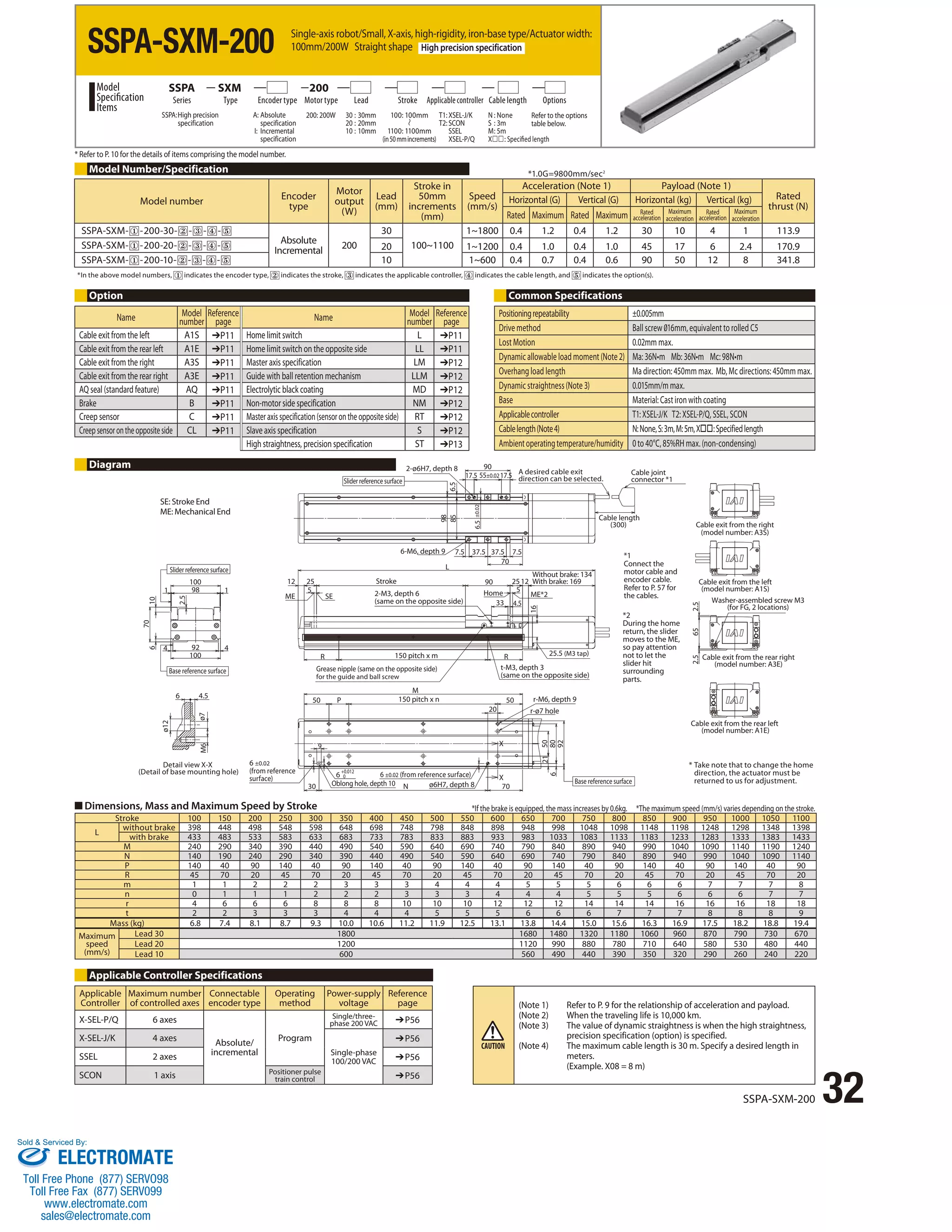
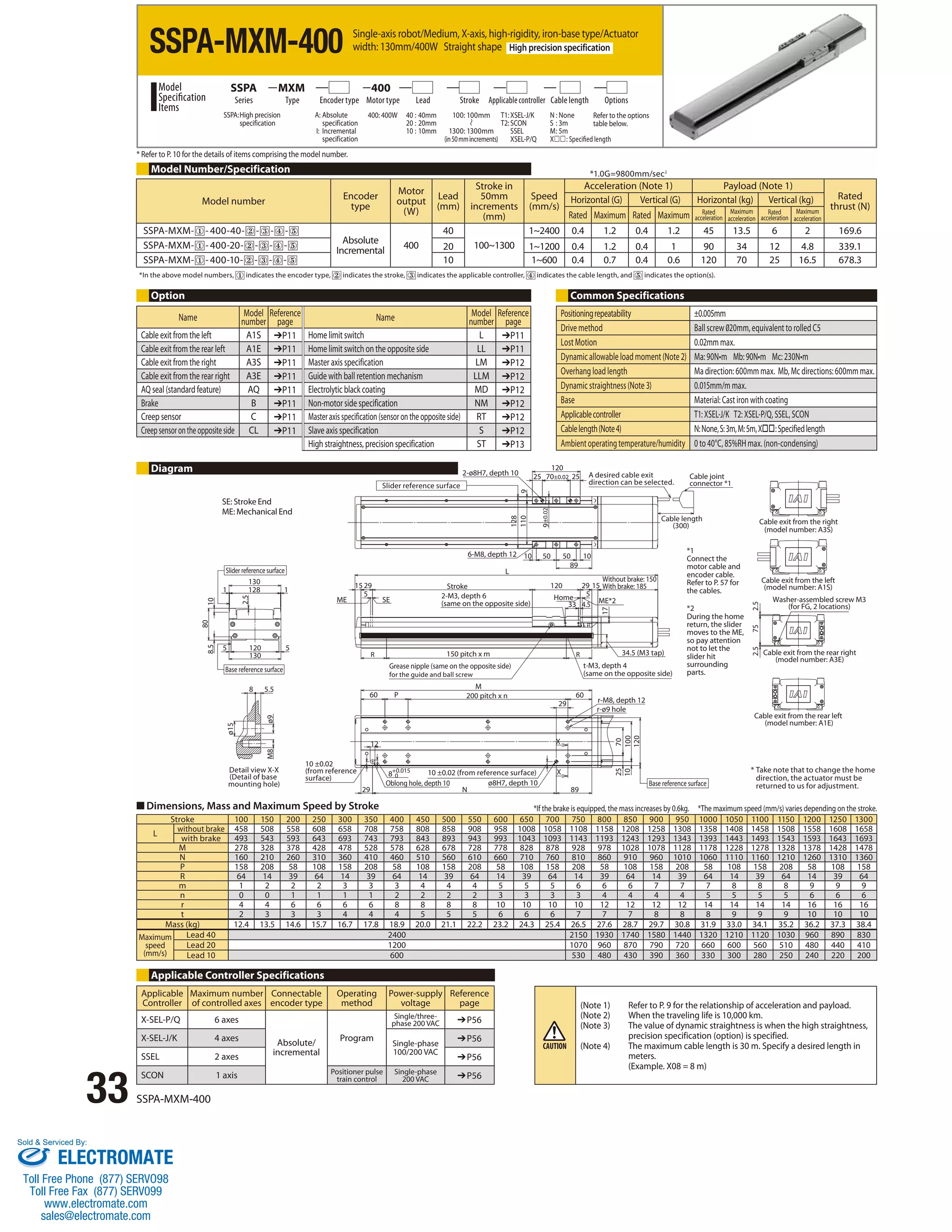

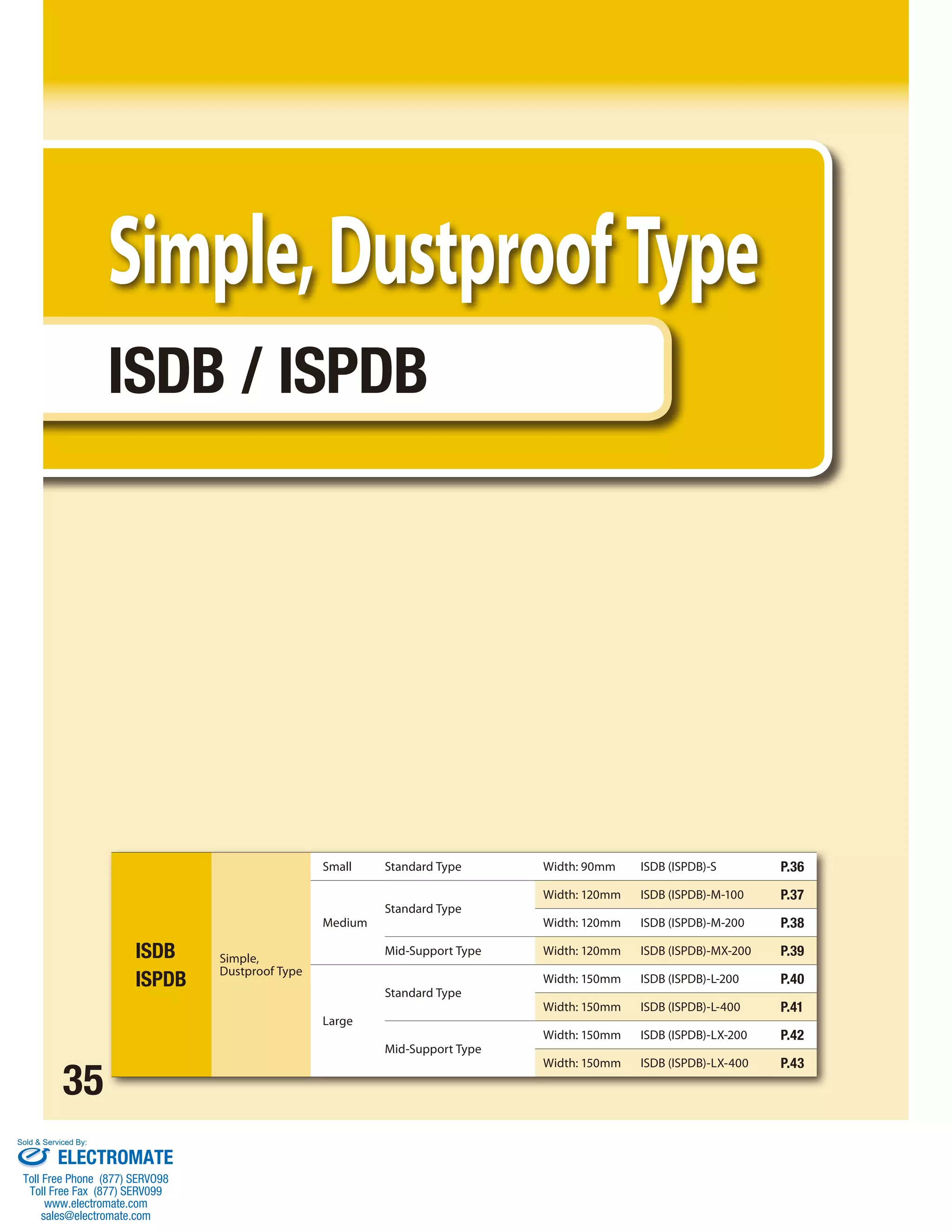
![Single-axis robot/Small, dustproof type/Actuator width: 90mm/60W
Straight shape
Single-axis robot/Small, dustproof type/Actuator width: 90mm/60W
Straight shape High precision specification
S 60
Series Type Encoder type Motor type Lead Stroke Applicable controller Cable length Options
N : None
S : 3m
M : 5m
X: Specified length
Refer to the options
table below.
*1.0G=9800mm/sec2
Acceleration (Note 1) Payload (Note 1)
Rated
Horizontal (G) Vertical (G) Horizontal (kg) Vertical (kg)** thrust (N)
Rated Maximum Rated Maximum Rated
acceleration
Maximum
acceleration
Rated
acceleration
Maximum
acceleration
T1: XSEL-J/K
T2: SCON
SSEL
XSEL-P/Q
1~960 0.4 1.0 0.4 0.8 13 4.5 3 2 53.1
ISDB-S
ISPDB-S
100: 100mm
800: 800mm
(in 50mm increments)
ISDB: Standard
specification
ISPDB: High precision
specification
A: Absolute
specification
I: Incremental
specification
60: 60W 16 : 16mm
8 : 8mm
4 : 4mm
Model
Specification
Items
* Refer to P. 10 for the details of items comprising the model number.
ISDB[ISPDB]-S- ① -60-8- ② - ③ - ④ - ⑤ 8 1~480 0.4 0.7 0.4 0.6 27 12 6 5 106.1
ISDB[ISPDB]-S- ① -60-4- ② - ③ - ④ - ⑤ 4 1~240 0.2 0.5 0.2 0.4 55 30 14 12 212.3
* In the above model numbers, indicates the encoder type, indicates the stroke, indicates the applicable controller, indicates the cable length, and indicates the option(s).
** If the guide with ball retention mechanism (RT) is used, the vertical payload decreases by 0.5kg. (Please also refer to P.9).
Option Common Specifications
Positioning repeatability (Note 2) ±0.01mm [±0.005mm]
Drive method (Note 3) Ball screw ø12mm, rolled C10 [equivalent to rolled C5]
Lost Motion (Note 4) 0.05mm [0.02mm] max.
Dynamic allowable load moment (Note 5) Ma: 28.4N•m Mb: 40.2N•m Mc: 65.7N•m
Overhang load length Ma direction: 450mm max. Mb, Mc directions: 450mm max.
Dynamic straightness (Note 6) 0.02mm/m max.
Base Material: Aluminum, with white alumite treatment
Applicable controller T1: XSEL-J/K T2: XSEL-P/Q, SSEL, SCON
Cable length (Note 7) N: None, S: 3m, M: 5m, X: Specified length
Protection structure IP30
Ambient operating temperature/humidity 0 to 40°C, 85%RH max. (non-condensing)
*1
Connect the motor cable and
encoder cable. Refer to P. 57 for
the cables.
*2
During the home return, the
slider moves to the ME, so pay
attention not to let the slider hit
surrounding parts.
ISDB-S/ISPDB-S 36
Model Number/Specification
Model number Encoder
ISDB[ISPDB]-S- ① -60-16- ② - ③ - ④ - ⑤
Name Model
number
Cable exit from the left A1S ➔P11 Home limit switch L ➔P11
Cable exit from the rear left A1E ➔P11 Home limit switch on the opposite side LL ➔P11
Cable exit from the right A3S ➔P11 Master axis specification LM ➔P12
Cable exit from the rear right A3E ➔P11 Master axis specification (sensor on the opposite side) LLM ➔P12
AQ seal (standard feature) AQ ➔P11 Non-motor side specification NM ➔P12
Brake B ➔P11 Guide with ball retention mechanism RT ➔P12
Creep sensor C ➔P11 Slave axis specification S ➔P12
Creep sensor on the opposite side CL ➔P11 High straightness, precision specification ST ➔P13
4.3
7.3
Reference
page Name Model
1.5 4.5
Detail view of A
Reference surface
A
SE: Stroke End
ME: Mechanical End
90 10 5
70
51
Processing jig holes are provided over
the entire bottom surface of the base.
They are not used for mounting the actuator.
They are plugged with rubber grommets.
Base mounting surface when the guide
is of the high precision specication
15
(38)
84
90
3
6
54.5 (2.5)
74.5
(1)
ME
Motor
output
(W)
Absolute
Incremental 60
Stroke
type
Lead
(mm)
16
Tapered screw for tube (Rc 3/8)
(Buried plug screw, same on the opposite side)
90
Speed
(mm/s)
10 70 10
45 45
Reference
page
Tapered screw for tube (Rc 3/8)
Stroke in
50mm
increments
(mm)
100~800
number
(Buried plug screw, same on the opposite side)
Cable exit from the right (model number: A3S)
Cable exit from the rear right (model number: A3E)
Cable joint connector *1
Grease nipple
for ball screw
Grease nipple for guide
(for greasing the guide on
the mounting surface side)
SE Home
11
+0.012
0 4-ø6H7, depth 10
7.5 100 F D× 200
7 70
8
25
57.5 50
22
B
L
7 (from reference surface)
86
ME*2
Slider center position
(home)
50 75.5
100 25.5
70±0.02
B
5 4
82.5 (without brake)
117.5 (with brake)
154
10
5
86
60±0.02
60
Cable length
(300)
Cable exit from the rear left
(model number: A1E)
Cable exit from the left
(model number: A1S)
ø6
View B
(Grease nipple, same on the opposite side)
Ground wire connection screw
(M3, 2 locations)
60
Reference
surface
2-oblong hole 6H7 depth 10
2-ø6H7, depth 10
4-M6, depth 19
E-M6, depth 17
Stroke 100 150 200 250 300 350 400 450 500 550 600 650 700 750 800
L without brake 382.5 432.5 482.5 532.5 582.5 632.5 682.5 732.5 782.5 832.5 882.5 932.5 982.5 1032.5 1082.5
with brake 417.5 467.5 517.5 567.5 617.5 667.5 717.5 767.5 817.5 867.5 917.5 967.5 1017.5 1067.5 1117.5
B 278 328 378 428 478 528 578 628 678 728 778 828 878 928 978
D 0 0 0 0 1 1 1 1 2 2 2 2 3 3 3
E 8 8 8 8 10 10 10 10 12 12 12 12 14 14 14
F 45 95 145 195 45 95 145 195 45 95 145 195 45 95 145
Mass (kg) 4.1 4.4 4.8 5.1 5.5 5.9 6.2 6.6 7.0 7.3 7.7 8.1 8.4 8.8 9.1
Maximum
speed
(mm/s)
Lead 16 960 920 795 690 610 540 480
Lead 8 480 460 400 345 305 270 240
Lead 4 240 230 200 170 150 135 120
Diagram
(Note 1) Refer to P. 9 for the relationship of acceleration and payload.
(Notes 2, 3, 4) The values in [ ] apply to the ISPDB series. Other specification
values apply commonly to the ISDB and ISPDB.
(Note 5) When the traveling life is 10,000km.
(Note 6) The value of dynamic straightness is when the high straightness,
precision specification (option) is specified.
(Note 7) The maximum cable length is 30m. Specify a desired length in
meters.
(Example. X08 = 8m)
Applicable Controller Specifications
Applicable
Maximum number
Connectable
Controller
of controlled axes
encoder type
Operating
method
Power-supply
voltage
Reference
page
X-SEL-P/Q 6 axes
Absolute/
incremental
Program
Single/three-phase
200 VAC ➔P56
X-SEL-J/K 4 axes
Single-phase
100/200 VAC
➔P56
SSEL 2 axes ➔P56
SCON 1 axis Positioner pulse
train control ➔P56
* Take note that to change the home
direction, the actuator must be
returned to us for adjustment.
■ Dimensions, Mass and Maximum Speed by Stroke *If the brake is equipped, the mass increases by 0.2kg. *The maximum speed (mm/s) varies depending on the stroke.
Sold Serviced By:
ELECTROMATE
Toll Free Phone (877) SERVO98
Toll Free Fax (877) SERV099
www.electromate.com
sales@electromate.com](https://image.slidesharecdn.com/iaiisbsspacatalog-141008213452-conversion-gate01/75/Iai-isb-sspa_catalog-37-2048.jpg)
![Single-axis robot/Medium, dustproof type/Actuator width:
120mm/100W Straight shape
Single-axis robot/Medium, dustproof type/Actuator width:
120mm/100W Straight shape High precision specification
Series Type Encoder type Motor type Lead Stroke Applicable controller Cable length Options
* Refer to P. 10 for the details of items comprising the model number.
Model Number/Specification
Model number Encoder
ISDB[ISPDB]-M- ① -100-30- ② - ③ - ④ - ⑤
*1.0G=9800mm/sec2
ISDB[ISPDB]-M- ① -100-20- ② - ③ - ④ - ⑤ 20 1~1200 0.4 1.0 0.4 1.0 23 8 4 2.5 84.9
ISDB[ISPDB]-M- ① -100-10 - ② - ③ - ④ - ⑤ 10 1~600 0.4 0.7 0.4 0.6 45 20 10 7 169.8
ISDB[ISPDB]-M- ① -100-5- ② - ③ - ④ - ⑤ 5 1~300 0.2 0.5 0.2 0.4 85 45 20 15 339.7
Option Common Specifications
4.3
7.3
1.5 4.5
A
94
Detail view of A
94
69
(2.5)
(1)
6
116
69.5
(54)
22
5 110
120
type
Motor
output
(W)
Lead
(mm)
Stroke in 50mm
increments
(mm)
Absolute
Incremental 100
30
100~1100
22 B
12.5
30
12
72.5
60
120
10 90
F
Acceleration (Note 1) Payload (Note 1)
Horizontal (G) Vertical (G) Horizontal (kg) Vertical (kg)**
Rated Maximum Rated Maximum Rated
1~1800 0.4 1.0 0.4 1.0 15 4 2 1.2 56.6
15
194 5 5
90±0.02
60 102.5
L
15
25
Speed
(mm/s)
D×200 120 42.5
11
55.5
8 5
ME SE
B
10
80±0.02
80
120
90
70
25
107
60 60
7
Rated
thrust (N)
Maximum
acceleration
Rated
acceleration
Maximum
acceleration
Cable exit from the right (model number: A3S)
Cable exit from the rear right (model number: A3E)
Cable joint connector *1
ø6
78
Reference
surface
Processing jig holes are provided over
the entire bottom surface of the base.
They are not used for mounting the
actuator. They are plugged with rubber grommets.
Base mounting surface when the guide
is of the high precision speci€cation
acceleration
107
Cable length
(300)
Slider center position
10 (from reference surface) (home)
Tapered screw for tube (Rc 3/8)
(Buried plug screw, same on the opposite side)
+0.015
0
2-oblong hole 6H7 depth 10
Tapered screw for tube (Rc 3/8)
(Buried plug screw, same on the opposite side) 91 (without brake)
115 (with brake) Ground wire connection screw
(M3, 2 locations)
View B
(Grease nipple,
same on the opposite side)
Home ME*2
Cable exit from the rear left
(model number: A1E)
Cable exit from the left
(model number: A1S)
Grease nipple
for ball screw
Grease nipple for guide
(for greasing the guide on
the mounting surface side)
2-ø8H7, depth 10
4-M6, depth 18 4-M8, depth 19
Stroke
Reference
surface
4-ø8H7, depth 10 E-M8, depth 20
37 ISDB-M-100/ISPDB-M-100
Positioning repeatability (Note 2) ±0.01mm [±0.005mm]
Drive method (Note 3) Ball screw ø16mm, rolled C10 [equivalent to rolled C5]
Lost Motion (Note 4) 0.05mm [0.02mm] max.
Dynamic allowable load moment (Note 5) Ma: 69.6N•m Mb: 99.0N•m Mc: 161.7N•m
Overhang load length Ma direction: 600mm max. Mb, Mc directions: 600mm max.
Dynamic straightness (Note 6) 0.02mm/m max.
Base Material: Aluminum, with white alumite treatment
Applicable controller T1: XSEL-J/K T2: XSEL-P/Q, SSEL, SCON
Cable length (Note 7) N: None, S: 3m, M: 5m, X: Specified length
Protection structure IP30
Ambient operating temperature/humidity 0 to 40°C, 85%RH max. (non-condensing)
*1
Connect the motor cable and
encoder cable. Refer to P. 57 for
the cables.
*2
During the home return, the
slider moves to the ME, so pay
attention not to let the slider
hit surrounding parts.
Stroke 100 150 200 250 300 350 400 450 500 550 600 650 700 750 800 850 900 950 1000 1050 1100
L without brake 430 480 530 580 630 680 730 780 830 880 930 980 1030 1080 1130 1180 1230 1280 1330 1380 1430
with brake 454 504 554 604 654 704 754 804 854 904 954 1004 1054 1104 1154 1204 1254 1304 1354 1404 1454
B 317 367 417 467 517 567 617 667 717 767 817 867 917 967 1017 1067 1117 1167 1217 1267 1317
D 0 0 0 0 1 1 1 1 2 2 2 2 3 3 3 3 4 4 4 4 5
E 8 8 8 8 10 10 10 10 12 12 12 12 14 14 14 14 16 16 16 16 18
F 22 72 122 172 22 72 122 172 22 72 122 172 22 72 122 172 22 72 122 172 22
Mass (kg) 7.5 8.1 8.8 9.4 10.0 10.7 11.3 11.9 12.6 13.2 13.8 14.5 15.1 15.7 16.4 17.0 17.6 18.3 18.9 19.5 20.2
Maximum
speed
(mm/s)
Lead 30 1800 1630 1440 1280 1150 1035 935 850 780 715 660
Lead 20 1200 1085 960 855 765 690 625 570 520 475 440
Lead 10 600 545 480 430 380 345 310 285 260 240 220
Lead 5 300 270 240 215 190 170 155 140 130 120 110
Diagram
SE: Stroke End
ME: Mechanical End
* Take note that to change the home
direction, the actuator must be
returned to us for adjustment.
■ Dimensions, Mass and Maximum Speed by Stroke *If the brake is equipped, the mass increases by 0.3kg. *The maximum speed (mm/s) varies depending on the stroke.
(Note 1) Refer to P. 9 for the relationship of acceleration and payload.
(Notes 2, 3, 4) The values in [ ] apply to the ISPDB series. Other specification
values apply commonly to the ISDB and ISPDB.
(Note 5) When the traveling life is 10,000km.
(Note 6) The value of dynamic straightness is when the high straightness,
precision specification (option) is specified.
(Note 7) The maximum cable length is 30m. Specify a desired length in
meters.
(Example. X08 = 8m)
Applicable Controller Specifications
Applicable
Maximum number
Connectable
Controller
of controlled axes
encoder type
Operating
method
Power-supply
voltage
Reference
page
X-SEL-P/Q 6 axes
Absolute/
incremental
Program
Single/three-phase
200 VAC ➔P56
X-SEL-J/K 4 axes
Single-phase
100/200 VAC
➔P56
SSEL 2 axes ➔P56
SCON 1 axis Positioner pulse
train control ➔P56
ISDB-M-100
ISPDB-M-100
100: 100mm
1100: 1100mm
(in 50mm increments)
ISDB: Standard
specification
ISPDB: High precision
specification
A: Absolute
specification
I: Incremental
specification
100: 100W 30 : 30mm
20: 20mm
10: 10mm
5 : 5mm
Model
Specification
Items
M 100
T1: XSEL-J/K
T2: SCON
SSEL
XSEL-P/Q
N : None
S : 3m
M : 5m
X: Specified length
Refer to the options
table below.
* In the above model numbers, indicates the encoder type, indicates the stroke, indicates the applicable controller, indicates the cable length, and indicates the option(s).
** If the guide with ball retention mechanism (RT) is used, the vertical payload decreases by 0.5kg. (Please also refer to P.9).
Name Model
number
Reference
page Name Model
number
Reference
page
Cable exit from the left A1S ➔P11 Home limit switch L ➔P11
Cable exit from the rear left A1E ➔P11 Home limit switch on the opposite side LL ➔P11
Cable exit from the right A3S ➔P11 Master axis specification LM ➔P12
Cable exit from the rear right A3E ➔P11 Master axis specification (sensor on the opposite side) LLM ➔P12
AQ seal (standard feature) AQ ➔P11 Non-motor side specification NM ➔P12
Brake B ➔P11 Guide with ball retention mechanism RT ➔P12
Creep sensor C ➔P11 Slave axis specification S ➔P12
Creep sensor on the opposite side CL ➔P11 High straightness, precision specification ST ➔P13
Sold Serviced By:
ELECTROMATE
Toll Free Phone (877) SERVO98
Toll Free Fax (877) SERV099
www.electromate.com
sales@electromate.com](https://image.slidesharecdn.com/iaiisbsspacatalog-141008213452-conversion-gate01/75/Iai-isb-sspa_catalog-38-2048.jpg)
![Single-axis robot/Medium, dustproof type/Actuator width: 120mm/200W
Straight shape
Single-axis robot/Medium, dustproof type/Actuator width: 120mm/200W
Straight shape High precision specification
Series Type Encoder type Motor type Lead Stroke Applicable controller Cable length Options
* Refer to P. 10 for the details of items comprising the model number.
Model Number/Specification
*In the above model numbers, indicates the encoder type, indicates the stroke, indicates the applicable controller, indicates the cable length, and indicates the option(s).
4.3
7.3
1.5 4.5
Detail view of A
Reference
surface
2-oblong hole 8H7 depth 10
11
Processing jig holes are provided over
the entire bottom surface of the base.
Reference
They are not used for mounting the
surface
actuator. They are plugged with rubber grommets. 12.5 120 F
A
94
116
94
69
(2.5)
(1)
6
110
5
120
69.5
(54)
22
Base mounting surface when the guide
is of the high precision specication
30
72.5
90
12
10
60
+0.015
0
*1.0G=9800mm/sec2
120
15 90 15
25 70 25
2-ø8H7, depth 10
4-M8, depth 18
194 5 5
Cable exit from the rear left
(model number: A1E)
Cable exit from the left
(model number: A1S)
4-ø8H7, depth 10 E-M8, depth 20
102.5
90±0.02
60
D×200 120 42.5
8 5
ME SE
22
55.5
L
B
B
10
80
60 60
7
107
Cable exit from the right (model number: A3S)
Cable exit from the rear right (model number: A3E)
ø6
Grease nipple
for ball screw
Grease nipple for guide
(for greasing the guide on
the mounting surface side)
(Grease nipple,
same on the opposite side)
78
Stroke
Tapered screw for tube (Rc 3/8)
(Buried plug screw, same on the opposite side)
4-M6, depth 18
80±0.02
Home ME*2
Cable length
(300)
Cable joint connector *1
View B
Ground wire connection screw
(M3, 2 locations)
106 (without brake)
141 (with brake)
Tapered screw for tube (Rc 3/8)
(Buried plug screw, same on the opposite side)
10 (from reference surface)
107
Slider center position
(home)
ISDB-M-200
ISPDB-M-200
*1
Connect the motor cable and
encoder cable. Refer to P. 57 for
the cables.
*2
During the home return, the
slider moves to the ME, so pay
attention not to let the slider hit
surrounding parts.
*If the brake is equipped, the mass increases by 0.4kg. *The maximum speed (mm/s) varies depending on the stroke.
■ Dimensions, Mass and Maximum Speed by Stroke
Stroke 100 150 200 250 300 350 400 450 500 550 600 650 700 750 800 850 900 950 1000 1050 1100
L without brake 445 495 545 595 645 695 745 795 845 895 945 995 1045 1095 1145 1195 1245 1295 1345 1395 1445
with brake 480 530 580 630 680 730 780 830 880 930 980 1030 1080 1130 1180 1230 1280 1330 1380 1430 1480
B 317 367 417 467 517 567 617 667 717 767 817 867 917 967 1017 1067 1117 1167 1217 1267 1317
D 0 0 0 0 1 1 1 1 2 2 2 2 3 3 3 3 4 4 4 4 5
E 8 8 8 8 10 10 10 10 12 12 12 12 14 14 14 14 16 16 16 16 18
F 22 72 122 172 22 72 122 172 22 72 122 172 22 72 122 172 22 72 122 172 22
Mass (kg) 7.9 8.5 9.2 9.8 10.4 11.1 11.7 12.3 13.0 13.6 14.2 14.9 15.5 16.1 16.8 17.4 18.0 18.7 19.3 19.9 20.6
ISDB-M-200/ISPDB-M-200 38
Maximum
speed
(mm/s)
Lead 30 1800 1630 1440 1280 1150 1035 935 850 780 715 660
Lead 20 1200 1085 960 855 765 690 625 570 520 475 440
Lead 10 600 545 480 430 380 345 310 285 260 240 220
Lead 5 300 270 240 215 190 170 155 140 130 120 110
Option
Diagram
SE: Stroke End
ME: Mechanical End
Applicable Controller Specifications
Applicable
Maximum number
Connectable
Controller
of controlled axes
encoder type
Operating
method
Power-supply
voltage
Reference
page
X-SEL-P/Q 6 axes
Absolute/
incremental
Program
Single/three-phase
200 VAC ➔P56
X-SEL-J/K 4 axes
Single-phase
100/200 VAC
➔P56
SSEL 2 axes ➔P56
SCON 1 axis Positioner pulse
train control ➔P56
Common Specifications
Model number Encoder
type
Motor
output
(W)
Lead
(mm)
Stroke in 50mm
increments
(mm)
Speed
(mm/s)
Acceleration (Note 1) Payload (Note 1)
Rated
thrust (N)
Horizontal (G) Vertical (G) Horizontal (kg) Vertical (kg)
Rated Maximum Rated Maximum Rated
acceleration
Maximum
acceleration
Rated
acceleration
Maximum
acceleration
ISDB[ISPDB]-M- ① -200-30- ② - ③ - ④ - ⑤
Absolute
Incremental 200
30
100~1100
1~1800 0.4 1.0 0.4 1.0 30 12 6 3 113.9
ISDB[ISPDB]-M- ① -200-20- ② - ③ - ④ - ⑤ 20 1~1200 0.4 1.0 0.4 1.0 45 16 10 5 170.9
ISDB[ISPDB]-M- ① -200-10 - ② - ③ - ④ - ⑤ 10 1~600 0.4 0.7 0.4 0.6 90 40 20 15 341.8
ISDB[ISPDB]-M- ① -200-5- ② - ③ - ④ - ⑤ 5 1~300 0.2 0.5 0.2 0.4 110 80 40 30 683.6
Positioning repeatability (Note 2) ±0.01mm [±0.005mm]
Drive method (Note 3) Ball screw ø16mm, rolled C10 [equivalent to rolled C5]
Lost Motion (Note 4) 0.05mm [0.02mm] max.
Dynamic allowable load moment (Note 5) Ma: 69.6N•m Mb: 99.0N•m Mc: 161.7N•m
Overhang load length Ma direction: 600mm max. Mb, Mc directions: 600mm max.
Dynamic straightness (Note 6) 0.02mm/m max.
Base Material: Aluminum, with white alumite treatment
Applicable controller T1: XSEL-J/K T2: XSEL-P/Q, SSEL, SCON
Cable length (Note 7) N: None, S: 3m, M: 5m, X: Specified length
Protection structure IP30
Ambient operating temperature/humidity 0 to 40°C, 85%RH max. (non-condensing)
* Take note that to change the home
direction, the actuator must be
returned to us for adjustment.
(Note 1) Refer to P. 9 for the relationship of acceleration and payload.
(Notes 2, 3, 4) The values in [ ] apply to the ISPDB series. Other specification
values apply commonly to the ISDB and ISPDB.
(Note 5) When the traveling life is 10,000km.
(Note 6) The value of dynamic straightness is when the high straightness,
precision specification (option) is specified.
(Note 7) The maximum cable length is 30m. Specify a desired length in
meters.
(Example. X08 = 8m)
100: 100mm
1100: 1100mm
(in 50mm increments)
ISDB: Standard
specification
ISPDB: High precision
specification
A: Absolute
specification
I: Incremental
specification
200: 200W 30 : 30mm
20: 20mm
10: 10mm
5 : 5mm
Model
Specification
Items
M 200
T1: XSEL-J/K
T2: SCON
SSEL
XSEL-P/Q
N : None
S : 3m
M : 5m
X: Specified length
Refer to the options
table below.
Name Model
number
Reference
page Name Model
number
Reference
page
Cable exit from the left A1S ➔P11 Home limit switch L ➔P11
Cable exit from the rear left A1E ➔P11 Home limit switch on the opposite side LL ➔P11
Cable exit from the right A3S ➔P11 Master axis specification LM ➔P12
Cable exit from the rear right A3E ➔P11 Master axis specification (sensor on the opposite side) LLM ➔P12
AQ seal (standard feature) AQ ➔P11 Non-motor side specification NM ➔P12
Brake B ➔P11 Guide with ball retention mechanism RT ➔P12
Creep sensor C ➔P11 Slave axis specification S ➔P12
Creep sensor on the opposite side CL ➔P11 High straightness, precision specification ST ➔P13
Sold Serviced By:
ELECTROMATE
Toll Free Phone (877) SERVO98
Toll Free Fax (877) SERV099
www.electromate.com
sales@electromate.com](https://image.slidesharecdn.com/iaiisbsspacatalog-141008213452-conversion-gate01/75/Iai-isb-sspa_catalog-39-2048.jpg)
![Single-axis robot/Medium, dustproof, mid-support type/Actuator
width: 120mm/200W Straight shape
Single-axis robot/Medium, dustproof, mid-support type/Actuator
width: 120mm/200W Straight shape High precision specification
Series Type Encoder type Motor type Lead Stroke Applicable controller Cable length Options
* Refer to P. 10 for the details of items comprising the model number.
Model Number/Specification
*In the above model numbers, indicates the encoder type, indicates the stroke, indicates the applicable controller, indicates the cable length, and indicates the option(s).
7.3
1.5 4.5
4.3
5
116
94
69
(54)
110
120
22
A
69.5 (2.5)
94
6
Processing jig holes are provided
over the entire bottom surface of
the base. They are not used for
mounting the actuator. They are
plugged with rubber grommets.
■ Dimensions, Mass and Maximum Speed by Stroke
ISDB-MX-200/ISPDB-MX-200 39
ME SE
11
120.5
30
+0.015
0
60.5 120 D×200
90
12
10
60
*1.0G=9800mm/sec2
15 90 15
60 60
194 5 53
Home ME*2
4-ø8H7, depth 10 E-M8, depth 20
150.5 60
F 120 90.5
56 5
L
22 B
B
10
80
155
25 70 25
7
ø6
Grease nipple for guide
(for greasing the guide on
the mounting surface side)
78
Detail view of A
Reference
surface
Reference
surface
Base mounting surface when the guide
is of the high precision speci‚cation
2-oblong hole 8H7 depth 10
10 (from reference surface)
155
Slider center position (home)
90±0.02
106
(without brake)
141 (with brake)
Tapered screw for tube (Rc 3/8)
(Buried plug screw, same on the opposite side)
Stroke
Tapered screw for tube (Rc 3/8)
(Buried plug screw, same on the opposite side)
4-M6, depth 18
80±0.02
Cable length
(300)
Cable exit from the left
(model number: A1S)
Cable exit
from the rear left
(model number: A1E)
Grease
nipple for
ball screw
View B
(Grease nipple,
same on the opposite side)
Ground wire
connection screw
(M3, 2 locations)
2-ø8H7, depth 10
4-M8, depth 18
Cable exit from the right
(model number: A3S)
Cable exit from the rear right
(model number: A3E)
Cable joint connector *1
*1
Connect the motor
cable and encoder
cable. Refer to P. 57
for the cables.
*2
During the home
return, the slider
moves to the ME, so
pay attention not to
let the slider hit
surrounding parts.
*If the brake is equipped, the mass increases by 0.5kg. *The maximum speed (mm/s) varies depending on the stroke.
Stroke 800 900 1000 1100 1200 1300 1400 1500 1600
L without brake 1241 1341 1441 1541 1641 1741 1841 1941 2041
with brake 1276 1376 1476 1576 1676 1776 1876 1976 2076
B 1113 1213 1313 1413 1513 1613 1713 1813 1913
D 3 3 4 4 5 5 6 6 7
E 14 14 16 16 18 18 20 20 22
F 122 222 122 222 122 222 122 222 122
Mass (kg) 18.3 19.6 20.9 22.2 23.4 24.7 26.0 27.3 28.6
Maximum
speed (mm/s)
Lead 30 1800 1650 1500 1425 1200 1050
Lead 20 1200 1100 1000 950 800 700
Option
Diagram
SE: Stroke End
ME: Mechanical End
Applicable Controller Specifications
Applicable
Maximum number
Connectable
Controller
of controlled axes
encoder type
Operating
method
Power-supply
voltage
Reference
page
X-SEL-P/Q 6 axes
Absolute/
incremental
Program
Single/three-phase
200 VAC ➔P56
X-SEL-J/K 4 axes
Single-phase
100/200 VAC
➔P56
SSEL 2 axes ➔P56
SCON 1 axis Positioner pulse
train control ➔P56
Common Specifications
Positioning repeatability (Note 2) ±0.01mm [±0.005mm]
Drive method (Note 3) Ball screw ø16mm, rolled C10 [equivalent to rolled C5]
Lost Motion (Note 4) 0.05mm [0.02mm] max.
Dynamic allowable load moment (Note 5) Ma: 69.6N•m Mb: 99.0N•m Mc: 161.7N•m
Overhang load length Ma direction: 600mm max. Mb, Mc directions: 600mm max.
Dynamic straightness (Note 6) 0.02mm/m max.
Base Material: Aluminum, with white alumite treatment
Applicable controller T1: XSEL-J/K T2: XSEL-P/Q, SSEL, SCON
Cable length (Note 7) N: None, S: 3m, M: 5m, X: Specified length
Protection structure IP30
Ambient operating temperature/humidity 0 to 40°C, 85%RH max. (non-condensing)
* Take note that to change the home
direction, the actuator must be
returned to us for adjustment.
Model number Encoder
type
Motor
output
(W)
Lead
(mm)
Stroke in100mm
increments
(mm)
Speed
(mm/s)
Acceleration (Note 1) Payload (Note 1)
Rated
Horizontal (G) Vertical (G) Horizontal (kg) Vertical (kg) thrust (N)
Rated Maximum Rated Maximum Rated
acceleration
Maximum
acceleration
Rated
acceleration
Maximum
acceleration
ISDB[ISPDB]-MX- ① -200-30- ② - ③ - ④ - ⑤ Absolute
Incremental 200
30
800~1600
1~1800 0.4 Designed
exclusively for
horizontal use
30 Designed
exclusively for
horizontal use
113.9
ISDB[ISPDB]-MX- ① -200-20- ② - ③ - ④ - ⑤ 20 1~1200 0.4 45 170.9
(Note 1) Refer to P. 9 for the relationship of acceleration and payload.
(Notes 2, 3, 4) The values in [ ] apply to the ISPDB series. Other specification
values apply commonly to the ISDB and ISPDB.
(Note 5) When the traveling life is 10,000km.
(Note 6) The value of dynamic straightness is when the high straightness,
precision specification (option) is specified.
(Note 7) The maximum cable length is 30m. Specify a desired length in
meters.
(Example. X08 = 8m)
ISDB-MX-200
ISPDB-MX-200
ISDB: Standard
specification
ISPDB: High precision
specification
A: Absolute
specification
I: Incremental
specification
200: 200W 30 : 30mm
20: 20mm
Model
Specification
Items
MX 200
T1: XSEL-J/K
T2: SCON
SSEL
XSEL-P/Q
N : None
S : 3m
M : 5m
X: Specified length
Refer to the options
table below.
800: 800mm
1600: 1600mm
(in 100mm increments)
Name Model
number
Reference
page Name Model
number
Reference
page
Cable exit from the left A1S ➔P11 Home limit switch L ➔P11
Cable exit from the rear left A1E ➔P11 Home limit switch on the opposite side LL ➔P11
Cable exit from the right A3S ➔P11 Master axis specification LM ➔P12
Cable exit from the rear right A3E ➔P11 Master axis specification (sensor on the opposite side) LLM ➔P12
AQ seal (standard feature) AQ ➔P11 Non-motor side specification NM ➔P12
Brake B ➔P11 Guide with ball retention mechanism RT ➔P12
Creep sensor C ➔P11 Slave axis specification S ➔P12
Creep sensor on the opposite side CL ➔P11 High straightness, precision specification ST ➔P13
Sold Serviced By:
ELECTROMATE
Toll Free Phone (877) SERVO98
Toll Free Fax (877) SERV099
www.electromate.com
sales@electromate.com](https://image.slidesharecdn.com/iaiisbsspacatalog-141008213452-conversion-gate01/75/Iai-isb-sspa_catalog-40-2048.jpg)
![Single-axis robot/Large, dustproof type/Actuator width: 150mm/200W
Straight shape
Single-axis robot/Large, dustproof type/Actuator width: 150mm/200W
Straight shape High precision specification
Series Type Encoder type Motor type Lead Stroke Applicable controller Cable length Options
*1.0G=9800mm/sec2
Acceleration (Note 1) Payload (Note 1)
Cable length
(300)
ø6
Grease nipple for guide
(for greasing the guide on
the mounting surface side)
*1
Connect the motor cable
and encoder cable. Refer
to P. 57 for the cables.
*2
During the home return,
the slider moves to the ME,
so pay attention not to let
the slider hit surrounding
parts.
ISDB-L-200/ISPDB-L-200 40
* Refer to P. 10 for the details of items comprising the model number.
Model number Encoder
7.3
1.5 4.5
4.3
A
112
143
121
93
6 (3)
140
150
5
81.5
(74)
22
(1.5)
Reference
surface
ME SE
Reference
surface
Processing jig holes are provided
over the entire bottom surface of
the base. They are not used for
mounting the actuator. They are
plugged with rubber grommets.
Base mounting surface when the guide
is of the high precision specication
100
10
10
60 50
120
25
12
122
75 75
224 5 5
75 99.5
117
(without brake)
151 (with brake)
Stroke in 50mm
increments
(mm)
Speed
(mm/s)
D×200 150 24.5
type
F
19 5
22
11
B
L
B
12
150
15 15
120
30 90 30
8
105 ±0.02
105
93
Detail view of A
Lead
(mm)
Stroke
Motor
output
(W)
Tapered screw for tube (Rc 3/8)
(Buried plug screw, same on the opposite side)
+0.015
0
2-oblong hole 8H7 depth 10
10 (from reference surface)
122
Slider center position
(home)
Tapered screw for tube (Rc 3/8)
(Buried plug screw, same on the opposite side)
4-ø8H7, depth 10
E-M8, depth 20
120±0.02
Home ME*2
Ground wire
connection screw
(M4, 2 locations)
Cable exit from the left
(model number: A1S)
Cable exit from the rear left
(model number: A1E)
Grease nipple
for ball screw
View B
(Grease nipple, same on the opposite side)
2-ø8H7, depth 10
8-M8, depth 20
Cable exit from the right
(model number: A3S)
Cable exit from the rear right
(model number: A3E)
Cable joint connector *1
Model Number/Specification
Option Common Specifications
Rated
Horizontal (G) Vertical (G) Horizontal (kg) Vertical (kg)** thrust (N)
Rated Maximum Rated Maximum Rated
acceleration
Maximum
acceleration
Rated
acceleration
Maximum
acceleration
ISDB[ISPDB]-L- ① -200-40- ② - ③ - ④ - ⑤
Absolute
Incremental 200
40
100~1300
1~1800 0.4 1.0 0.4 1.0 15 7 2.5 2 85.5
ISDB[ISPDB]-L- ① -200-20- ② - ③ - ④ - ⑤ 20 1~1200 0.4 1.0 0.4 1.0 45 15 9 5 170.9
ISDB[ISPDB]-L- ① -200-10 - ② - ③ - ④ - ⑤ 10 1~600 0.4 0.7 0.4 0.6 90 40 20 14 341.8
Positioning repeatability (Note 2) ±0.01mm [±0.005mm]
Drive method (Note 3) Ball screw ø20mm, rolled C10 [equivalent to rolled C5]
Lost Motion (Note 4) 0.05mm [0.02mm] max.
Dynamic allowable load moment (Note 5) Ma: 104.9N•m Mb: 149.9N•m Mc: 248.9N•m
Overhang load length Ma direction: 750mm max. Mb, Mc directions: 750mm max.
Dynamic straightness (Note 6) 0.02mm/m max.
Base Material: Aluminum, with white alumite treatment
Applicable controller T1: XSEL-J/K T2: XSEL-P/Q, SSEL, SCON
Cable length (Note 7) N: None, S: 3m, M: 5m, X: Specified length
Protection structure IP30
Ambient operating temperature/humidity 0 to 40°C, 85%RH max. (non-condensing)
Diagram
SE: Stroke End
ME: Mechanical End
■ Dimensions, Mass and Maximum Speed by Stroke
* Take note that to change the home
direction, the actuator must be
returned to us for adjustment.
Applicable Controller Specifications
Applicable
Maximum number
Connectable
Controller
of controlled axes
encoder type
Operating
method
Power-supply
voltage
Reference
page
X-SEL-P/Q 6 axes
Absolute/
incremental
Program
Single/three-phase
200 VAC ➔P56
X-SEL-J/K 4 axes
Single-phase
100/200 VAC
➔P56
SSEL 2 axes ➔P56
SCON 1 axis Positioner pulse
train control ➔P56
*If the brake is equipped, the mass increases by 0.5kg. *The maximum speed (mm/s) varies depending on the stroke.
Stroke 100 150 200 250 300 350 400 450 500 550 600 650 700 750 800 850 900 950 1000 1050 1100 1150 1200 1250 1300
L without brake 497 547 597 647 697 747 797 847 897 947 997 1047 1097 1147 1197 1247 1297 1347 1397 1447 1497 1547 1597 1647 1697
with brake 531 581 631 681 731 781 831 881 931 981 1031 1081 1131 1181 1231 1281 1331 1381 1431 1481 1531 1581 1631 1681 1731
B 358 408 458 508 558 608 658 708 758 808 858 908 958 1008 1058 1108 1158 1208 1258 1308 1358 1408 1458 1508 1558
D 0 0 0 1 1 1 1 2 2 2 2 3 3 3 3 4 4 4 4 5 5 5 5 6 6
E 8 8 8 10 10 10 10 12 12 12 12 14 14 14 14 16 16 16 16 18 18 18 18 20 20
F 73.5 123.5 173.5 23.5 73.5 123.5 173.5 23.5 73.5 123.5 173.5 23.5 73.5 123.5 173.5 23.5 73.5 123.5 173.5 23.5 73.5 123.5 173.5 23.5 73.5
Mass (kg) 11.8 12.7 13.6 14.4 15.3 16.2 17.0 17.9 18.8 19.6 20.5 21.4 22.3 23.1 24.0 24.9 25.7 26.6 27.5 28.3 29.2 30.1 31.0 31.8 32.7
Maximum
speed
(mm/s)
Lead 40 1800 1700 1540 1410 1290 1185 1095 1015 940 875 815
Lead 20 1200 1165 1045 940 850 770 705 645 595 545 505 470 440 410
Lead 10 600 585 520 470 425 385 350 320 295 275 255 235 220 205
(Note 1) Refer to P. 9 for the relationship of acceleration and payload.
(Notes 2, 3, 4) The values in [ ] apply to the ISPDB series. Other specification
values apply commonly to the ISDB and ISPDB.
(Note 5) When the traveling life is 10,000km.
(Note 6) The value of dynamic straightness is when the high straightness,
precision specification (option) is specified.
(Note 7) The maximum cable length is 30m. Specify a desired length in
meters.
(Example. X08 = 8m)
ISDB-L-200
ISPDB-L-200
100: 100mm
1300: 1300mm
(in 50mm increments)
ISDB: Standard
specification
ISPDB: High precision
specification
A: Absolute
specification
I: Incremental
specification
200: 200W 40 : 40mm
20 : 20mm
10: 10mm
Model
Specification
Items
L 200
T1: XSEL-J/K
T2: SCON
SSEL
XSEL-P/Q
N : None
S : 3m
M : 5m
X: Specified length
Refer to the options
table below.
* In the above model numbers, indicates the encoder type, indicates the stroke, indicates the applicable controller, indicates the cable length, and indicates the option(s).
** If the guide with ball retention mechanism (RT) is used, the vertical payload decreases by 1.0kg. (Please also refer to P.9).
Name Model
number
Reference
page Name Model
number
Reference
page
Cable exit from the left A1S ➔P11 Home limit switch L ➔P11
Cable exit from the rear left A1E ➔P11 Home limit switch on the opposite side LL ➔P11
Cable exit from the right A3S ➔P11 Master axis specification LM ➔P12
Cable exit from the rear right A3E ➔P11 Master axis specification (sensor on the opposite side) LLM ➔P12
AQ seal (standard feature) AQ ➔P11 Non-motor side specification NM ➔P12
Brake B ➔P11 Guide with ball retention mechanism RT ➔P12
Creep sensor C ➔P11 Slave axis specification S ➔P12
Creep sensor on the opposite side CL ➔P11 High straightness, precision specification ST ➔P13
Sold Serviced By:
ELECTROMATE
Toll Free Phone (877) SERVO98
Toll Free Fax (877) SERV099
www.electromate.com
sales@electromate.com](https://image.slidesharecdn.com/iaiisbsspacatalog-141008213452-conversion-gate01/75/Iai-isb-sspa_catalog-41-2048.jpg)
![ISDB-L-400
ISPDB-L-400
Single-axis robot/Large, dustproof type/Actuator width: 150mm/400W
Straight shape
Single-axis robot/Large, dustproof type/Actuator width: 150mm/400W
Straight shape High precision specification
Series Type Encoder type Motor type Lead Stroke Applicable controller Cable length Options
ISDB: Standard
specification
ISPDB: High precision
specification
* Refer to P. 10 for the details of items comprising the model number.
Model number Encoder
*In the above model numbers, indicates the encoder type, indicates the stroke, indicates the applicable controller, indicates the cable length, and indicates the option(s).
7.3
1.5 4.5
4.3
6 (3)
A
112
143
121
93
(74)
140
5
150
81.5
Processing jig holes are provided
over the entire bottom surface of
the base. They are not used for
mounting the actuator. They are
plugged with rubber grommets.
41 ISDB-L-400/ISPDB-L-400
22
(1.5)
Reference
surface
A: Absolute
specification
I: Incremental
specification
19 5
ME SE
Reference
surface
Base mounting surface when the guide
is of the high precision specication
22
11
100: 100mm
1300: 1300mm
(in 50mm increments)
Stroke in 50mm
increments
(mm)
B
L
400: 400W 40 : 40mm
20 : 20mm
10: 10mm
type
Motor
output
(W)
Lead
(mm)
Tapered screw for tube (Rc 3/8)
(Buried plug screw, same on the opposite side)
100 F
10
10
60 50
120
25
12
*1.0G=9800mm/sec2
Acceleration (Note 1) Payload (Note 1)
150
120
90
122
15 15
30 30
75 75
224 5 5
B
8
Home ME*2
75 99.5
12
105
Speed
(mm/s)
D×200 150 24.5
Cable exit from the right
(model number: A3S)
Cable exit from the rear right
(model number: A3E)
Cable joint connector *1
93
Detail view of A
2-oblong hole 8H7+0.015 depth 10
0
Stroke
Tapered screw for tube (Rc 3/8)
(Buried plug screw, same on the opposite side) 139 (without brake)
173 (with brake)
120±0.02
10 (from reference surface)
122
Cable length
(300)
Slider center position
(home)
4-ø8H7, depth 10
E-M8, depth 20
105±0.02
2-ø8H7, depth 10
8-M8, depth 20
Cable exit from the left
(model number: A1S)
Cable exit from
the rear left
(model number: A1E)
ø6
Grease nipple
for ball screw
Grease nipple for guide
(for greasing the guide on
the mounting surface side)
View B
(Grease nipple, same on the opposite side)
Ground wire
connection screw
(M4, 2 locations)
*1
Connect the motor cable
and encoder cable. Refer
to P. 57 for the cables.
*2
During the home return,
the slider moves to the ME,
so pay attention not to let
the slider hit surrounding
parts.
Stroke 100 150 200 250 300 350 400 450 500 550 600 650 700 750 800 850 900 950 1000 1050 1100 1150 1200 1250 1300
L without brake 519 569 619 669 719 769 819 869 919 969 1019 1069 1119 1169 1219 1269 1319 1369 1419 1469 1519 1569 1619 1669 1719
with brake 553 603 653 703 753 803 853 903 953 1003 1053 1103 1153 1203 1253 1303 1353 1403 1453 1503 1553 1603 1653 1703 1753
B 358 408 458 508 558 608 658 708 758 808 858 908 958 1008 1058 1108 1158 1208 1258 1308 1358 1408 1458 1508 1558
D 0 0 0 1 1 1 1 2 2 2 2 3 3 3 3 4 4 4 4 5 5 5 5 6 6
E 8 8 8 10 10 10 10 12 12 12 12 14 14 14 14 16 16 16 16 18 18 18 18 20 20
F 73.5 123.5 173.5 23.5 73.5 123.5 173.5 23.5 73.5 123.5 173.5 23.5 73.5 123.5 173.5 23.5 73.5 123.5 173.5 23.5 73.5 123.5 173.5 23.5 73.5
Mass (kg) 12.2 13.1 14.0 14.8 15.7 16.6 17.4 18.3 19.2 20.0 20.9 21.8 22.7 23.5 24.4 25.3 26.1 27.0 27.9 28.7 29.6 30.5 31.4 32.2 33.1
Maximum
speed
(mm/s)
Lead 40 1800 1700 1540 1410 1290 1185 1095 1015 940 875 815
Lead 20 1200 1165 1045 940 850 770 705 645 595 545 505 470 440 410
Lead 10 600 585 520 470 425 385 350 320 295 275 255 235 220 205
Model
Specification
Items
L 400
T1: XSEL-J/K
T2: SCON
SSEL
XSEL-P/Q
N : None
S : 3m
M : 5m
X: Specified length
Refer to the options
table below.
Model Number/Specification
Option Common Specifications
Rated
Horizontal (G) Vertical (G) Horizontal (kg) Vertical (kg) thrust (N)
Rated Maximum Rated Maximum Rated
acceleration
Maximum
acceleration
Rated
acceleration
Maximum
acceleration
ISDB[ISPDB]-L- ① -400-40- ② - ③ - ④ - ⑤
Absolute
Incremental 400
40
100~1300
1~1800 0.4 1.0 0.4 1.0 40 17 8 5 169.6
ISDB[ISPDB]-L- ① -400-20- ② - ③ - ④ - ⑤ 20 1~1200 0.4 1.0 0.4 1.0 90 30 20 10 339.1
ISDB[ISPDB]-L- ① -400-10 - ② - ③ - ④ - ⑤ 10 1~600 0.4 0.7 0.4 0.6 120 60 40 30 678.3
Positioning repeatability (Note 2) ±0.01mm [±0.005mm]
Drive method (Note 3) Ball screw ø20mm, rolled C10 [equivalent to rolled C5]
Lost Motion (Note 4) 0.05mm [0.02mm] max.
Dynamic allowable load moment (Note 5) Ma: 104.9N•m Mb: 149.9N•m Mc: 248.9N•m
Overhang load length Ma direction: 750mm max. Mb, Mc directions: 750mm max.
Dynamic straightness (Note 6) 0.02mm/m max.
Base Material: Aluminum, with white alumite treatment
Applicable controller T1: XSEL-J/K T2: XSEL-P/Q, SSEL, SCON
Cable length (Note 7) N: None, S: 3m, M: 5m, X: Specified length
Protection structure IP30
Ambient operating temperature/humidity 0 to 40°C, 85%RH max. (non-condensing)
Diagram
SE: Stroke End
ME: Mechanical End
■ Dimensions, Mass and Maximum Speed by Stroke
* Take note that to change the home
direction, the actuator must be
returned to us for adjustment.
*If the brake is equipped, the mass increases by 0.5kg. *The maximum speed (mm/s) varies depending on the stroke.
(Note 1) Refer to P. 9 for the relationship of acceleration and payload.
(Notes 2, 3, 4) The values in [ ] apply to the ISPDB series. Other specification
values apply commonly to the ISDB and ISPDB.
(Note 5) When the traveling life is 10,000km.
(Note 6) The value of dynamic straightness is when the high straightness,
precision specification (option) is specified.
(Note 7) The maximum cable length is 30m. Specify a desired length in
meters.
(Example. X08 = 8m)
Name Model
number
Reference
page Name Model
number
Reference
page
Cable exit from the left A1S ➔P11 Home limit switch L ➔P11
Cable exit from the rear left A1E ➔P11 Home limit switch on the opposite side LL ➔P11
Cable exit from the right A3S ➔P11 Master axis specification LM ➔P12
Cable exit from the rear right A3E ➔P11 Master axis specification (sensor on the opposite side) LLM ➔P12
AQ seal (standard feature) AQ ➔P11 Non-motor side specification NM ➔P12
Brake B ➔P11 Guide with ball retention mechanism RT ➔P12
Creep sensor C ➔P11 Slave axis specification S ➔P12
Creep sensor on the opposite side CL ➔P11 High straightness, precision specification ST ➔P13
Applicable Controller Specifications
Applicable
Maximum number
Connectable
Controller
of controlled axes
encoder type
Operating
method
Power-supply
voltage
Reference
page
X-SEL-P/Q 6 axes
Absolute/
incremental
Program
Single/three-phase
200 VAC ➔P56
X-SEL-J/K 4 axes Single-phase
100/200 VAC
➔P56
SSEL 2 axes ➔P56
SCON 1 axis Positioner pulse
train control
Single-phase
200 VAC ➔P56
Sold Serviced By:
ELECTROMATE
Toll Free Phone (877) SERVO98
Toll Free Fax (877) SERV099
www.electromate.com
sales@electromate.com](https://image.slidesharecdn.com/iaiisbsspacatalog-141008213452-conversion-gate01/75/Iai-isb-sspa_catalog-42-2048.jpg)
![Single-axis robot/Large, dustproof, mid-support type/Actuator width:
150mm/200W Straight shape
Single-axis robot/Large, dustproof, mid-support type/Actuator width:
150mm/200W Straight shape High precision specification
Series Type Encoder type Motor type Lead Stroke Applicable controller Cable length Options
* Refer to P. 10 for the details of items comprising the model number.
Model Number/Specification
Model number Encoder
*1.0G=9800mm/sec2
*In the above model numbers, indicates the encoder type, indicates the stroke, indicates the applicable controller, indicates the cable length, and indicates the option(s).
Option Common Specifications
1.5 4.5
150
Cable exit from the right
(model number: A3S)
Cable exit from the rear right
(model number: A3E)
Cable joint connector *1
93 120 15 15
30 90 30
75 75
ø6
ISDB-LX-200/ISPDB-LX-200 42 4.3
7.3
112
6
A
143
121
5 140
150
81.5
(74)
22
(3)
93
Reference
surface
11
Stroke
22 B
Processing jig holes are provided
over the entire bottom surface of
the base. They are not used for
mounting the actuator. They are
plugged with rubber grommets. Reference
surface
Base mounting surface when the guide
is of the high precision specication
65 5
ME SE
100 F
10
56
106 50
120
12 25
L
117
(without brake)
151 (with brake)
4-ø8H7, depth 10
75 145.5
D×200 150
E-M8, depth 20
70.5
B
5 51
12
224
168
8
105±0.02
105
Detail view of A
2-oblong hole 8H7+0.015depth 10
0
10 (from reference surface)
120±0.02
168
Slider center position(home)
Tapered screw for tube (Rc 3/8)
(Buried plug screw, same on the opposite side)
Tapered screw for tube (Rc 3/8)
(Buried plug screw, same on the opposite side)
Home ME*2
Ground wire connection screw
(M4, 2 locations)
2-ø8H7, depth 10
8-M8, depth 20
Cable length
(300)
Cable exit from the left
(model number: A1S)
Cable exit from
the rear left
(model number: A1E)
Grease nipple
for ball screw
Grease nipple for guide
(for greasing the guide on
the mounting surface side)
View B
(Grease nipple,
same on the opposite side)
■ Dimensions, Mass and Maximum Speed by Stroke
*If the brake is equipped, the mass increases by 0.5kg. *The maximum speed (mm/s) varies depending on the stroke.
Stroke 1000 1100 1200 1300 1400 1500 1600
L without brake 1489 1589 1689 1789 1889 1989 2089
with brake 1523 1623 1723 1823 1923 2023 2123
B 1350 1450 1550 1650 1750 1850 1950
D 4 5 5 6 6 7 7
E 16 18 18 20 20 22 22
F 173.5 73.5 173.5 73.5 173.5 73.5 173.5
Mass (kg) 29.7 31.4 33.2 35.0 36.7 38.5 40.2
Maximum
speed (mm/s)
Lead 30 1800 1660
Lead 20 1200 1150 1000 950 830
Diagram
SE: Stroke End
ME: Mechanical End
type
Motor
output
(W)
Lead
(mm)
Stroke in 100mm
increments
(mm)
Speed
(mm/s)
Acceleration (Note 1) Payload (Note 1)
Rated
Horizontal (G) Vertical (G) Horizontal (kg) Vertical (kg) thrust (N)
Rated Maximum Rated Maximum Rated
acceleration
Maximum
acceleration
Rated
acceleration
Maximum
acceleration
ISDB[ISPDB]-LX- ① -200-40- ② - ③ - ④ - ⑤ Absolute
Incremental 200
40
1000~1600
1~1800 0.4 Designed
exclusively for
horizontal use
15 Designed
exclusively for
horizontal use
85.5
ISDB[ISPDB]-LX- ① -200-20- ② - ③ - ④ - ⑤ 20 1~1200 0.4 45 170.9
Positioning repeatability (Note 2) ±0.01mm [±0.005mm]
Drive method (Note 3) Ball screw ø16mm, rolled C10 [equivalent to rolled C5]
Lost Motion (Note 4) 0.05mm [0.02mm] max.
Dynamic allowable load moment (Note 5) Ma: 104.9N•m Mb: 149.9N•m Mc: 248.9N•m
Overhang load length Ma direction: 750mm max. Mb, Mc directions: 750mm max.
Dynamic straightness (Note 6) 0.02mm/m max.
Base Material: Aluminum, with white alumite treatment
Applicable controller T1: XSEL-J/K T2: XSEL-P/Q, SSEL, SCON
Cable length (Note 7) N: None, S: 3m, M: 5m, X: Specified length
Protection structure IP30
Ambient operating temperature/humidity 0 to 40°C, 85%RH max. (non-condensing)
Applicable Controller Specifications
Applicable
Maximum number
Connectable
Controller
of controlled axes
encoder type
Operating
method
Power-supply
voltage
Reference
page
X-SEL-P/Q 6 axes
Absolute/
incremental
Program
Single/three-phase
200 VAC ➔P56
X-SEL-J/K 4 axes
Single-phase
100/200 VAC
➔P56
SSEL 2 axes ➔P56
SCON 1 axis Positioner pulse
train control ➔P56
*1
Connect the motor
cable and encoder
cable. Refer to P. 57
for the cables.
*2
During the home
return, the slider
moves to the ME, so
pay attention not to
let the slider hit
surrounding parts.
(Note 1) Refer to P. 9 for the relationship of acceleration and payload.
(Notes 2, 3, 4) The values in [ ] apply to the ISPDB series. Other specification
values apply commonly to the ISDB and ISPDB.
(Note 5) When the traveling life is 10,000km.
(Note 6) The value of dynamic straightness is when the high straightness,
precision specification (option) is specified.
(Note 7) The maximum cable length is 30m. Specify a desired length in
meters.
(Example. X08 = 8m)
* Take note that to change the home
direction, the actuator must be
returned to us for adjustment.
ISDB-LX-200
ISPDB-LX-200
1000: 1000mm
1600: 1600mm
(in 100mm increments)
ISDB: Standard
specification
ISPDB: High precision
specification
A: Absolute
specification
I: Incremental
specification
200: 200W 40: 40mm
20: 20mm
Model
Specification
Items
LX 200
T1: XSEL-J/K
T2: SCON
SSEL
XSEL-P/Q
N : None
S : 3m
M : 5m
X: Specified length
Refer to the options
table below.
Name Model
number
Reference
page Name Model
number
Reference
page
Cable exit from the left A1S ➔P11 Home limit switch L ➔P11
Cable exit from the rear left A1E ➔P11 Home limit switch on the opposite side LL ➔P11
Cable exit from the right A3S ➔P11 Master axis specification LM ➔P12
Cable exit from the rear right A3E ➔P11 Master axis specification (sensor on the opposite side) LLM ➔P12
AQ seal (standard feature) AQ ➔P11 Non-motor side specification NM ➔P12
Brake B ➔P11 Guide with ball retention mechanism RT ➔P12
Creep sensor C ➔P11 Slave axis specification S ➔P12
Creep sensor on the opposite side CL ➔P11 High straightness, precision specification ST ➔P13
Sold Serviced By:
ELECTROMATE
Toll Free Phone (877) SERVO98
Toll Free Fax (877) SERV099
www.electromate.com
sales@electromate.com](https://image.slidesharecdn.com/iaiisbsspacatalog-141008213452-conversion-gate01/75/Iai-isb-sspa_catalog-43-2048.jpg)
![Single-axis robot/Large, dustproof, mid-support type/Actuator width:
150mm/400W Straight shape
Single-axis robot/Large, dustproof, mid-support type/Actuator width:
150mm/400W Straight shape High precision specification
Series Type Encoder type Motor type Lead Stroke Applicable controller Cable length Options
* Refer to P. 10 for the details of items comprising the model number.
Model Number/Specification
*1.0G=9800mm/sec2
*In the above model numbers, indicates the encoder type, indicates the stroke, indicates the applicable controller, indicates the cable length, and indicates the option(s).
Option Common Specifications
1.5 4.5
4.3
7.3
Detail view of A
A
(3)
112
81.5
6
Reference
surface
143
121
93
(74)
5 140
150
22
Processing jig holes are provided
over the entire bottom surface of
the base. They are not used for
mounting the actuator. They are
plugged with rubber grommets.
65 5
ME SE
11
Reference
surface
Base mounting surface when the guide
is of the high precision specication
■ Dimensions, Mass and Maximum Speed by Stroke
43 ISDB-LX-400/ISPDB-LX-400
100
10
56
106 50
120
25
12
2-oblong hole 8H7+0.015depth 10
0
150
15 120 15
30 90 30
10 (from reference surface)
5 51
4-ø8H7, depth 10
75 75
B
75 145.5
E-M8, depth 20
D×200 150 70.5
Cable exit from the right
(model number: A3S)
Cable exit from the rear right
(model number: A3E)
Cable joint connector *1
Cable exit from
the rear left
(model number: A1E)
168
Slider center position (home)
B
L
22
Stroke
Tapered screw for tube (Rc 3/8)
(Buried plug screw, same on the opposite side)
Tapered screw for tube (Rc 3/8)
(Buried plug screw, same on the opposite side)
12
224
Home ME*2
93
139
(without brake)
173 (with brake) Ground wire connection screw
(M4, 2 locations)
8
105±0.02
105
168
2-ø8H7, depth 10
8-M8, depth 20
ø6
Cable length
(300)
Cable exit from the left
(model number: A1S)
Grease nipple
for ball screw
Grease nipple for guide
(for greasing the guide on
the mounting surface side)
View B
(Grease nipple,
same on the opposite side)
F
120±0.02
*If the brake is equipped, the mass increases by 0.5kg. *The maximum speed (mm/s) varies depending on the stroke.
Stroke 1000 1100 1200 1300 1400 1500 1600
L without brake 1511 1611 1711 1811 1911 2011 2111
with brake 1545 1645 1745 1845 1945 2045 2145
B 1350 1450 1550 1650 1750 1850 1950
D 4 5 5 6 6 7 7
E 16 18 18 20 20 22 22
F 173.5 73.5 173.5 73.5 173.5 73.5 173.5
Mass (kg) 30.1 31.8 33.6 35.4 37.1 38.9 40.6
Maximum
speed (mm/s)
Lead 30 1800 1660
Lead 20 1200 1150 1000 950 830
Diagram
SE: Stroke End
ME: Mechanical End
*1
Connect the motor
cable and encoder
cable. Refer to P. 57
for the cables.
*2
During the home
return, the slider
moves to the ME, so
pay attention not to
let the slider hit
surrounding parts.
* Take note that to change the home
direction, the actuator must be
returned to us for adjustment.
Model number Encoder
type
Motor
output
(W)
Lead
(mm)
Stroke in 100mm
increments
(mm)
Speed
(mm/s)
Acceleration (Note 1) Payload (Note 1)
Rated
Horizontal (G) Vertical (G) Horizontal (kg) Vertical (kg) thrust (N)
Rated Maximum Rated Maximum Rated
acceleration
Maximum
acceleration
Rated
acceleration
Maximum
acceleration
ISDB[ISPDB]-LX- ① -400-40- ② - ③ - ④ - ⑤ Absolute
Incremental 400
40
1000~1600
1~1800 0.4 Designed
exclusively for
horizontal use
40 Designed
exclusively for
horizontal use
169.6
ISDB[ISPDB]-LX- ① -400-20- ② - ③ - ④ - ⑤ 20 1~1200 0.4 90 339.1
Positioning repeatability (Note 2) ±0.01mm [±0.005mm]
Drive method (Note 3) Ball screw ø20mm, rolled C10 [equivalent to rolled C5]
Lost Motion (Note 4) 0.05mm [0.02mm] max.
Dynamic allowable load moment (Note 5) Ma: 104.9N•m Mb: 149.9N•m Mc: 248.9N•m
Overhang load length Ma direction: 750mm max. Mb, Mc directions: 750mm max.
Dynamic straightness (Note 6) 0.02mm/m max.
Base Material: Aluminum, with white alumite treatment
Applicable controller T1: XSEL-J/K T2: XSEL-P/Q, SSEL, SCON
Cable length (Note 7) N: None, S: 3m, M: 5m, X: Specified length
Protection structure IP30
Ambient operating temperature/humidity 0 to 40°C, 85%RH max. (non-condensing)
Applicable Controller Specifications
Applicable
Maximum number
Connectable
Controller
of controlled axes
encoder type
Operating
method
Power-supply
voltage
Reference
page
X-SEL-P/Q 6 axes
Absolute/
incremental
Program
Single/three-phase
200 VAC ➔P56
X-SEL-J/K 4 axes Single-phase
100/200 VAC
➔P56
SSEL 2 axes ➔P56
SCON 1 axis Positioner pulse
train control
Single-phase
200 VAC ➔P56
ISDB-LX-400
ISPDB-LX-400
1000: 1000mm
1600: 1600mm
(in 100mm increments)
ISDB: Standard
specification
ISPDB: High precision
specification
A: Absolute
specification
I: Incremental
specification
400: 400W 40: 40mm
20: 20mm
Model
Specification
Items
LX 400
T1: XSEL-J/K
T2: SCON
SSEL
XSEL-P/Q
N : None
S : 3m
M : 5m
X: Specified length
Refer to the options
table below.
(Note 1) Refer to P. 9 for the relationship of acceleration and payload.
(Notes 2, 3, 4) The values in [ ] apply to the ISPDB series. Other specification
values apply commonly to the ISDB and ISPDB.
(Note 5) When the traveling life is 10,000km.
(Note 6) The value of dynamic straightness is when the high straightness,
precision specification (option) is specified.
(Note 7) The maximum cable length is 30m. Specify a desired length in
meters.
(Example. X08 = 8m)
Name Model
number
Reference
page Name Model
number
Reference
page
Cable exit from the left A1S ➔P11 Home limit switch L ➔P11
Cable exit from the rear left A1E ➔P11 Home limit switch on the opposite side LL ➔P11
Cable exit from the right A3S ➔P11 Master axis specification LM ➔P12
Cable exit from the rear right A3E ➔P11 Master axis specification (sensor on the opposite side) LLM ➔P12
AQ seal (standard feature) AQ ➔P11 Non-motor side specification NM ➔P12
Brake B ➔P11 Guide with ball retention mechanism RT ➔P12
Creep sensor C ➔P11 Slave axis specification S ➔P12
Creep sensor on the opposite side CL ➔P11 High straightness, precision specification ST ➔P13
Sold Serviced By:
ELECTROMATE
Toll Free Phone (877) SERVO98
Toll Free Fax (877) SERV099
www.electromate.com
sales@electromate.com](https://image.slidesharecdn.com/iaiisbsspacatalog-141008213452-conversion-gate01/75/Iai-isb-sspa_catalog-44-2048.jpg)
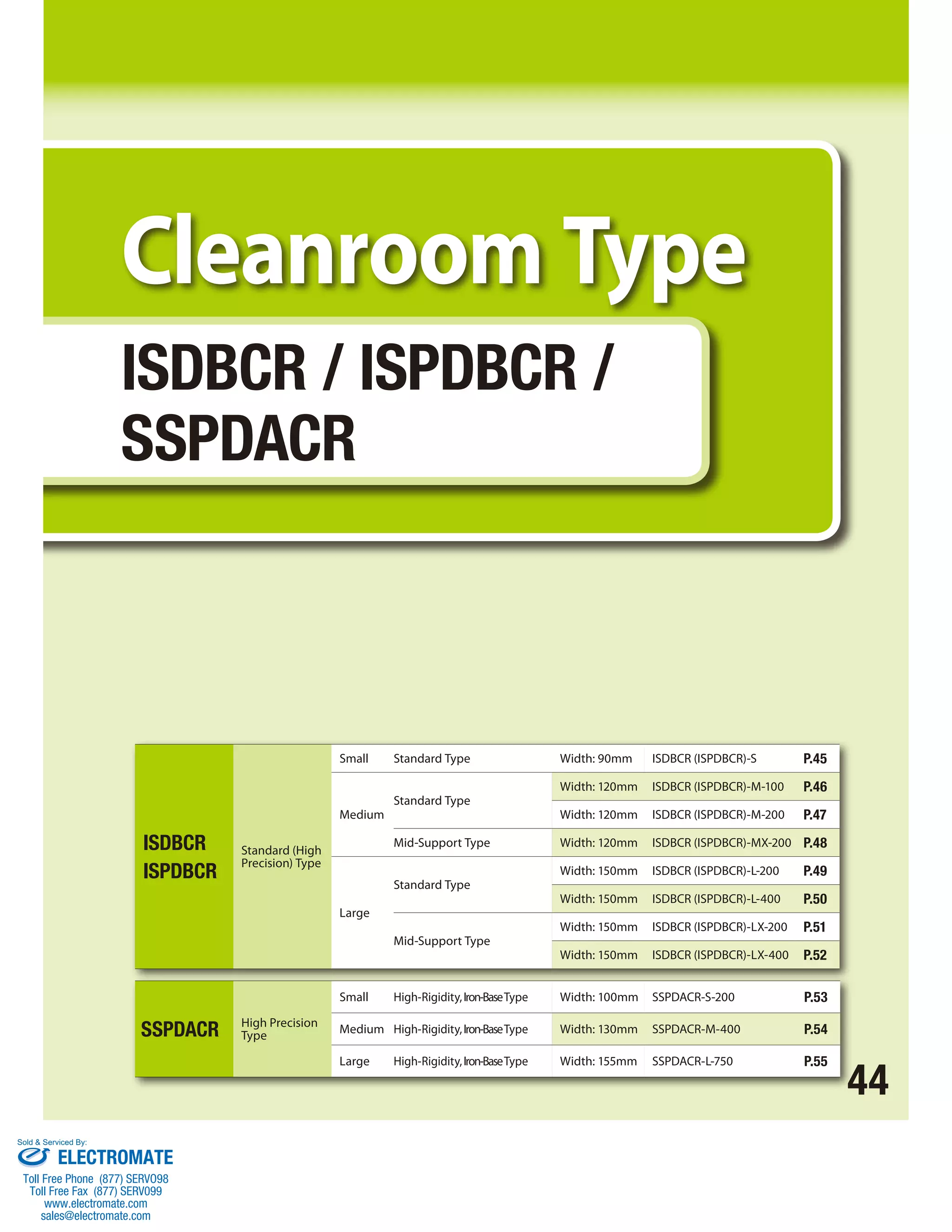
![Single-axis robot for cleanroom/Small/Actuator width: 90mm/60 W
Straight shape
Single-axis robot for cleanroom/Small/Actuator width: 90mm/60 W
Straight shape High precision specification
Series Type Encoder type Motor type Lead Stroke Applicable controller Cable length Options
* Refer to P. 10 for the details of items comprising the model number.
Model Number/Specification
Model number Encoder
type
Motor
output
(W)
Lead
(mm)
Stroke in
50mm
increments
(mm)
*1.0G=9800mm/sec2
Option Common Specifications
54.5 (2.5)
90
70
51
Processing jig holes are provided over the
entire bottom surface of the base. They are
not used for mounting the actuator.
They are plugged with rubber grommets. 7.5 100 F
■ Dimensions, Mass and Maximum Speed by Stroke
45 ISDBCR-S/ISPDBCR-S
1.5 4.5
7.3
4.3
Detail view of A
A
15
(38)
84
90 (32.5)
(53.5)
3
6
74.5
(1)
Reference
surface
Reference
surface
Base mounting surface when the guide
is of the high precision specication
7 70
8
25
57.5 50
10 5
22 B
L
ME SE
Positioning repeatability (Note 2) ±0.01mm [±0.005mm]
Drive method (Note 3) Ball screw ø12mm, rolled C10 [equivalent to rolled C5]
Lost Motion (Note 4) 0.05mm [0.02mm] max.
Dynamic allowable load moment (Note 5) Ma: 28.4N•m Mb: 40.2N•m Mc: 65.7N•m
Overhang load length Ma direction: 450mm max. Mb, Mc directions: 450mm max.
Dynamic straightness (Note 6) 0.02mm/m max.
Base Material: Aluminum, with white alumite treatment
Applicable controller T1: XSEL-J/K T2: XSEL-P/Q, SSEL, SCON
Cable length (Note 7) N: None, S: 3m, M: 5m, X: Specified length
Grease Low dust-raising grease (for ball screw and guide)
Cleanliness degree Class 10 (0.1μm per 1cf)
Suction tube joint Quick connect joint, applicable tube outer diameter ø12mm
90
86
10 70 10
45 45
60±0.02 5
154 5 4
Home ME*2
82.5 (without brake)
117.5 (with brake)
4-ø6H7, depth 10
50 75.5
100 25.5
70±0.02
60
7 (from reference surface)
D×200
Cable exit from
the rear left
(model number: A1E)
E-M6, depth 17
86
Slider center position
(home)
Stroke
2-oblong hole 6H7+0.012 depth 10
0
B
(38.5)
Air tube joint
Applicable tube outer diameter ø12 (inner diameterø8)
(Buried plug screw on the opposite side: Rc 3/8)
2-ø6H7, depth 10
4-M6, depth 19
Cable exit from the right
(model number: A3S)
Cable exit from the rear right
(model number: A3E)
Cable joint connector *1
Cable length
(300)
ø6
Cable exit from the left
(model number: A1S)
Grease nipple
for ball screw
Grease nipple for guide
(for greasing the guide on
the mounting surface side)
View B
(Grease nipple,
same on the opposite side)
Joint installation position: Standard
Joint installation position: Opposite side
Ground wire connection screw
(M3, 2 locations)
60
*1
Connect the motor cable and encoder
cable. Refer to P. 57 for the cables.
*2
During the home return, the slider
moves to the ME, so pay attention not
to let the slider hit surrounding parts.
* Take note that to change the home
direction, the actuator must be
returned to us for adjustment.
Stroke 100 150 200 250 300 350 400 450 500 550 600 650 700 750 800
L without brake 382.5 432.5 482.5 532.5 582.5 632.5 682.5 732.5 782.5 832.5 882.5 932.5 982.5 1032.5 1082.5
with brake 417.5 467.5 517.5 567.5 617.5 667.5 717.5 767.5 817.5 867.5 917.5 967.5 1017.5 1067.5 1117.5
B 278 328 378 428 478 528 578 628 678 728 778 828 878 928 978
D 0 0 0 0 1 1 1 1 2 2 2 2 3 3 3
E 8 8 8 8 10 10 10 10 12 12 12 12 14 14 14
F 45 95 145 195 45 95 145 195 45 95 145 195 45 95 145
Mass (kg) 4.2 4.5 4.9 5.2 5.6 6.0 6.3 6.7 7.0 7.4 7.8 8.1 8.5 8.9 9.2
Maximum
speed
(mm/s)
Lead 16 960 920 795 690 610 540 480
Lead 8 480 460 400 345 305 270 240
Lead 4 240 230 200 170 150 135 120
Diagram
SE: Stroke End
ME: Mechanical End
(Note 1) Refer to P. 9 for the relationship of acceleration and payload.
(Notes 2, 3, 4) The values in [ ] apply to the ISPDBCR series. Other
specification values apply commonly to the ISDBCR and ISPDBCR.
(Note 5) When the traveling life is 10,000km.
(Note 6) The value of dynamic straightness is when the high straightness,
precision specification (option) is specified.
(Note 7) The maximum cable length is 30m. Specify a desired length in
meters.
(Example. X08 = 8m)
Applicable Controller Specifications
Applicable
Maximum number
Connectable
Controller
of controlled axes
encoder type
Operating
method
Power-supply
voltage
Reference
page
X-SEL-P/Q 6 axes
Absolute/
incremental
Program
Single/three-phase
200 VAC ➔P56
X-SEL-J/K 4 axes
Single-phase
100/200 VAC
➔P56
SSEL 2 axes ➔P56
SCON 1 axis Positioner pulse
train control ➔P56
Speed
(mm/s)
Acceleration (Note 1) Payload (Note 1)
Rated
thrust
(N)
Suction
flow rate
(N /min)
Horizontal (G) Vertical (G) Horizontal (kg) Vertical (kg)**
Rated Maximum Rated Maximum Rated
acceleration
Maximum
acceleration
Rated
acceleration
Maximum
acceleration
ISDBCR[ISPDBCR]-S- ① -60-16- ② - ③ - ④ - ⑤
Absolute
Incremental 60
16
100~800
1~960 0.4 1.0 0.4 0.8 13 4.5 3 2 53.1 60
ISDBCR[ISPDBCR]-S- ① -60-8- ② - ③ - ④ - ⑤ 8 1~480 0.4 0.7 0.4 0.6 27 12 6 5 106.1 30
ISDBCR[ISPDBCR]-S- ① -60-4- ② - ③ - ④ - ⑤ 4 1~240 0.2 0.5 0.2 0.4 55 30 14 12 212.3 15
*If the brake is equipped, the mass increases by 0.2kg. *The maximum speed (mm/s) varies depending on the stroke.
ISDBCR-S
ISPDBCR-S
100: 100mm
800: 800mm
(in 50mm increments)
ISDBCR: Standard
specification
ISPDBCR: High precision
specification
A: Absolute
specification
I: Incremental
specification
60: 60W 16 : 16mm
8 : 8mm
4 : 4mm
Model
Specification
Items
S 60
T1: XSEL-J/K
T2: SCON
SSEL
XSEL-P/Q
N : None
S : 3m
M : 5m
X: Specified length
Refer to the options
table below.
* In the above model numbers, indicates the encoder type, indicates the stroke, indicates the applicable controller, indicates the cable length, and indicates the option(s).
** If the guide with ball retention mechanism (RT) is used, the vertical payload decreases by 0.5kg. (Please also refer to P.9).
Name Model
number
Reference
page Name Model
number
Reference
page
Cable exit from the left A1S ➔P11 Home limit switch L ➔P11
Cable exit from the rear left A1E ➔P11 Home limit switch on the opposite side LL ➔P11
Cable exit from the right A3S ➔P11 Master axis specification LM ➔P12
Cable exit from the rear right A3E ➔P11 Master axis specification (sensor on the opposite side) LLM ➔P12
AQ seal (standard feature) AQ ➔P11 Non-motor side specification NM ➔P12
Brake B ➔P11 Guide with ball retention mechanism RT ➔P12
Creep sensor C ➔P11 Slave axis specification S ➔P12
Creep sensor on the opposite side CL ➔P11 High straightness, precision specification ST ➔P13
Suction tube joint on the opposite side VR ➔P12
Sold Serviced By:
ELECTROMATE
Toll Free Phone (877) SERVO98
Toll Free Fax (877) SERV099
www.electromate.com
sales@electromate.com](https://image.slidesharecdn.com/iaiisbsspacatalog-141008213452-conversion-gate01/75/Iai-isb-sspa_catalog-46-2048.jpg)
![ISDBCR-M-100
ISPDBCR-M-100
Single-axis robot for cleanroom/Medium/Actuator width:
120mm/100W Straight shape
Single-axis robot for cleanroom/Medium/Actuator width:
120mm/100W Straight shape High precision specification
Series Type Encoder type Motor type Lead Stroke Applicable controller Cable length Options
ISDBCR: Standard
specification
ISPDBCR: High precision
specification
* Refer to P. 10 for the details of items comprising the model number.
Model Number/Specification
Model number Encoder
type
Motor
output
(W)
Lead
(mm)
Stroke in
50mm
increments
(mm)
*1.0G=9800mm/sec2
* In the above model numbers, indicates the encoder type, indicates the stroke, indicates the applicable controller, indicates the cable length, and indicates the option(s).
** If the guide with ball retention mechanism (RT) is used, the vertical payload decreases by 0.5kg. (Please also refer to P.9).
Option Common Specifications
1.5 4.5
15 90 15
ø6
100: 100mm
1100: 1100mm
(in 50mm increments)
A: Absolute
specification
I: Incremental
specification
100: 100W 30 : 30mm
20 : 20mm
10 : 10mm
5 : 5mm
SE: Stroke End
ME: Mechanical End
ISDBCR-M-100/ISPDBCR-M-100 46 7.3
4.3
Diagram
94
Detail view of A
116
94
69
(2.5)
(1)
6
110
5
120
(66)
69.5
(54)
ME SE
(32.5)
22
Reference
surface
Reference
surface
Processing jig holes are provided over the
entire bottom surface of the base. They
are not used for mounting the actuator.
They are plugged with rubber grommets.
Base mounting surface when the guide
is of the high precision specication
2-oblong hole 8H7 +0.015depth 10
0
30
72.5
12.5 120 F D×200
90
12
10
60
10 (from reference surface)
107
194 5 5
Home ME*2
(38.5)
Slider center position (home)
90±0.02
60 102.5
120 42.5
E-M8, depth 20
4-ø8H7, depth 10
8 5
22
Stroke
B
L
91 (without brake)
115 (with brake)
B
80±0.02
80
120
25 70 25
60 60
7
107
4-M6, depth 18
2-ø8H7, depth 10
4-M8, depth 18
Cable exit from the right
(model number: A3S)
Cable exit from the rear right
(model number: A3E)
Cable joint connector *1
Cable length
(300)
Cable exit from the rear left
(model number: A1E)
Cable exit from the left
(model number: A1S)
Air tube joint
Applicable tube outer diameter ø12 (inner diameter ø8)
(Buried plug screw on the opposite side: Rc 3/8)
Ground wire connection screw
(M3, 2 locations)
Grease nipple
for ball screw
Grease nipple for guide
(for greasing the guide on
the mounting surface side)
View B
(Grease nipple,
same on the opposite side)
Joint installation position: Standard
Joint installation position: Opposite side
78
A
*1
Connect the motor cable and encoder
cable. Refer to P. 57 for the cables.
*2
During the home return, the slider
moves to the ME, so pay attention not
to let the slider hit surrounding parts.
Stroke 100 150 200 250 300 350 400 450 500 550 600 650 700 750 800 850 900 950 1000 1050 1100
L without brake 430 480 530 580 630 680 730 780 830 880 930 980 1030 1080 1130 1180 1230 1280 1330 1380 1430
with brake 454 504 554 604 654 704 754 804 854 904 954 1004 1054 1104 1154 1204 1254 1304 1354 1404 1454
B 317 367 417 467 517 567 617 667 717 767 817 867 917 967 1017 1067 1117 1167 1217 1267 1317
D 0 0 0 0 1 1 1 1 2 2 2 2 3 3 3 3 4 4 4 4 5
E 8 8 8 8 10 10 10 10 12 12 12 12 14 14 14 14 16 16 16 16 18
F 22 72 122 172 22 72 122 172 22 72 122 172 22 72 122 172 22 72 122 172 22
Mass (kg) 7.6 8.2 8.8 9.5 10.1 10.7 11.3 12.0 12.6 13.2 13.9 14.5 15.1 15.7 16.4 17.0 17.6 18.2 18.9 19.5 20.1
Maximum
speed
(mm/s)
Lead 30 1800 1630 1440 1280 1150 1035 935 850 780 715 660
Lead 20 1200 1085 960 855 765 690 625 570 520 475 440
Lead 10 600 545 480 430 380 345 310 285 260 240 220
Lead 5 300 270 240 215 190 170 155 140 130 120 110
Model
Specification
Items
M 100
T1: XSEL-J/K
T2: SCON
SSEL
XSEL-P/Q
N : None
S : 3m
M : 5m
X: Specified length
Refer to the options
table below.
Positioning repeatability (Note 2) ±0.01mm [±0.005mm]
Drive method (Note 3) Ball screw ø16mm, rolled C10 [equivalent to rolled C5]
Lost Motion (Note 4) 0.05mm [0.02mm] max.
Dynamic allowable load moment (Note 5) Ma: 69.6N•m Mb: 99.0N•m Mc: 161.7N•m
Overhang load length Ma direction: 600mm max. Mb, Mc directions: 600mm max.
Dynamic straightness (Note 6) 0.02mm/m max.
Base Material: Aluminum, with white alumite treatment
Applicable controller T1: XSEL-J/K T2: XSEL-P/Q, SSEL, SCON
Cable length (Note 7) N: None, S: 3m, M: 5m, X: Specified length
Grease Low dust-raising grease (for ball screw and guide)
Cleanliness degree Class 10 (0.1μm per 1cf)
Suction tube joint Quick connect joint, applicable tube outer diameter ø12mm
■ Dimensions, Mass and Maximum Speed by Stroke
* Take note that to change the
home direction, the actuator must
be returned to us for adjustment.
Applicable Controller Specifications
Applicable
Maximum number
Connectable
Controller
of controlled axes
encoder type
Operating
method
Power-supply
voltage
Reference
page
X-SEL-P/Q 6 axes
Absolute/
incremental
Program
Single/three-phase
200 VAC ➔P56
X-SEL-J/K 4 axes
Single-phase
100/200 VAC
➔P56
SSEL 2 axes ➔P56
SCON 1 axis Positioner pulse
train control ➔P56
Speed
(mm/s)
Acceleration (Note 1) Payload (Note 1) Rated
thrust
(N)
Suction
flow rate
(N /min)
Horizontal (G) Vertical (G) Horizontal (kg) Vertical (kg)**
Rated Maximum Rated Maximum Rated
acceleration
Maximum
acceleration
Rated
acceleration
Maximum
acceleration
ISDBCR[ISPDBCR]-M- ① -100-30- ② - ③ - ④ - ⑤
Absolute
Incremental 100
30
100~1100
1~1800 0.4 1.0 0.4 1.0 15 4 2 1.2 56.6 180
ISDBCR[ISPDBCR]-M- ① -100-20- ② - ③ - ④ - ⑤ 20 1~1200 0.4 1.0 0.4 1.0 23 8 4 2.5 84.9 120
ISDBCR[ISPDBCR]-M- ① -100-10- ② - ③ - ④ - ⑤ 10 1~600 0.4 0.7 0.4 0.6 45 20 10 7 169.8 50
ISDBCR[ISPDBCR]-M- ① -100-5- ② - ③ - ④ - ⑤ 5 1~300 0.2 0.5 0.2 0.4 85 45 20 15 339.7 20
*If the brake is equipped, the mass increases by 0.3kg. *The maximum speed (mm/s) varies depending on the stroke.
(Note 1) Refer to P. 9 for the relationship of acceleration and payload.
(Notes 2, 3, 4) The values in [ ] apply to the ISPDBCR series. Other
specification values apply commonly to the ISDBCR and ISPDBCR.
(Note 5) When the traveling life is 10,000km.
(Note 6) The value of dynamic straightness is when the high straightness,
precision specification (option) is specified.
(Note 7) The maximum cable length is 30m. Specify a desired length in
meters.
(Example. X08 = 8m)
Name Model
number
Reference
page Name Model
number
Reference
page
Cable exit from the left A1S ➔P11 Home limit switch L ➔P11
Cable exit from the rear left A1E ➔P11 Home limit switch on the opposite side LL ➔P11
Cable exit from the right A3S ➔P11 Master axis specification LM ➔P12
Cable exit from the rear right A3E ➔P11 Master axis specification (sensor on the opposite side) LLM ➔P12
AQ seal (standard feature) AQ ➔P11 Non-motor side specification NM ➔P12
Brake B ➔P11 Guide with ball retention mechanism RT ➔P12
Creep sensor C ➔P11 Slave axis specification S ➔P12
Creep sensor on the opposite side CL ➔P11 High straightness, precision specification ST ➔P13
Suction tube joint on the opposite side VR ➔P12
Sold Serviced By:
ELECTROMATE
Toll Free Phone (877) SERVO98
Toll Free Fax (877) SERV099
www.electromate.com
sales@electromate.com](https://image.slidesharecdn.com/iaiisbsspacatalog-141008213452-conversion-gate01/75/Iai-isb-sspa_catalog-47-2048.jpg)
![Single-axis robot for cleanroom/Medium/Actuator width:
120mm/200W Straight shape
Single-axis robot for cleanroom/Medium/Actuator width:
120mm/200W Straight shape High precision specification
Series Type Encoder type Motor type Lead Stroke Applicable controller Cable length
* Refer to P. 10 for the details of items comprising the model number.
Model Number/Specification
Model number Encoder
type
Motor
output
(W)
Lead
(mm)
Stroke in
50mm
increments
(mm)
*1.0G=9800mm/sec2
*In the above model numbers, indicates the encoder type, indicates the stroke, indicates the applicable controller, indicates the cable length, and indicates the option(s).
Option Common Specifications
1.5 4.5
7.3
4.3
Diagram
6 (2.5)
A
94
Detail view of A
116
94
69
(1)
(54)
110
(66)
22
120 (32.5)
69.5
5
Reference
surface
SE: Stroke End
ME: Mechanical End
ME SE
Processing jig holes are provided over the
entire bottom surface of the base. They
Reference
surface
are not used for mounting the actuator.
They are plugged with rubber grommets. 12.5 120 F
47 ISDBCR-M-200/ISPDBCR-M-200
8 5
22
Stroke
Base mounting surface when the guide
is of the high precision specication
30
72.5
90
12
10
60
2-oblong hole 8H7 +0.015depth 10
0
Positioning repeatability (Note 2) ±0.01mm [±0.005mm]
Drive method (Note 3) Ball screw ø16mm, rolled C10 [equivalent to rolled C5]
Lost Motion (Note 4) 0.05mm [0.02mm] max.
Dynamic allowable load moment (Note 5) Ma: 69.6N•m Mb: 99.0N•m Mc: 161.7N•m
Overhang load length Ma direction: 600mm max. Mb, Mc directions: 600mm max.
Dynamic straightness (Note 6) 0.02mm/m max.
Base Material: Aluminum, with white alumite treatment
Applicable controller T1: XSEL-J/K T2: XSEL-P/Q, SSEL, SCON
Cable length (Note 7) N: None, S: 3m, M: 5m, X: Specified length
Grease Low dust-raising grease (for ball screw and guide)
Cleanliness degree Class 10 (0.1μm per 1cf)
Suction tube joint Quick connect joint, applicable tube outer diameter ø12mm
10 (from reference surface)
D×200
L
B
120
194 5 5
Home ME*2
106 (without brake)
141 (with brake)
107
4-ø8H7, depth 10
Cable exit from the right
(model number: A3S)
Cable exit from the rear right
(model number: A3E)
Slider center position (home)
60 102.5
120 42.5
90±0.02
E-M8, depth 20
(38.5)
B
80±0.02
80
4-M6, depth 18
15 90 15
25 70 25
60 60
7
107
2-ø8H7, depth 10
4-M8, depth 18
Cable length
(300)
ø6
Grease nipple
for ball screw
Grease nipple for guide
(for greasing the guide on
the mounting surface side)
Cable exit from the rear left
(model number: A1E)
Cable exit from the left
View B
(model number: A1S)
(Grease nipple,
same on the opposite side)
Air tube joint
Applicable tube outer diameter ø12 (inner diameter ø8)
(Buried plug screw on the opposite side: Rc 3/8)
Joint installation position: Standard
Joint installation position: Opposite side
Ground wire connection screw
(M3, 2 locations)
78
Cable joint connector *1
■ Dimensions, Mass and Maximum Speed by Stroke
*1
Connect the motor cable and encoder
cable. Refer to P. 57 for the cables.
*2
During the home return, the slider
moves to the ME, so pay attention not
to let the slider hit surrounding parts.
* Take note that to change the home
direction, the actuator must be
returned to us for adjustment.
Stroke 100 150 200 250 300 350 400 450 500 550 600 650 700 750 800 850 900 950 1000 1050 1100
L without brake 445 495 545 595 645 695 745 795 845 895 945 995 1045 1095 1145 1195 1245 1295 1345 1395 1445
with brake 480 530 580 630 680 730 780 830 880 930 980 1030 1080 1130 1180 1230 1280 1330 1380 1430 1480
B 317 367 417 467 517 567 617 667 717 767 817 867 917 967 1017 1067 1117 1167 1217 1267 1317
D 0 0 0 0 1 1 1 1 2 2 2 2 3 3 3 3 4 4 4 4 5
E 8 8 8 8 10 10 10 10 12 12 12 12 14 14 14 14 16 16 16 16 18
F 22 72 122 172 22 72 122 172 22 72 122 172 22 72 122 172 22 72 122 172 22
Mass (kg) 8.0 8.6 9.2 9.9 10.5 11.1 11.7 12.4 13.0 13.6 14.3 14.9 15.5 16.1 16.8 17.4 18.0 18.6 19.3 19.9 20.5
Maximum
speed
(mm/s)
Lead 30 1800 1630 1440 1280 1150 1035 935 850 780 715 660
Lead 20 1200 1085 960 855 765 690 625 570 520 475 440
Lead 10 600 545 480 430 380 345 310 285 260 240 220
Lead 5 300 270 240 215 190 170 155 140 130 120 110
Applicable Controller Specifications
Applicable
Maximum number
Connectable
Controller
of controlled axes
encoder type
Operating
method
Power-supply
voltage
Reference
page
X-SEL-P/Q 6 axes
Absolute/
incremental
Program
Single/three-phase
200 VAC ➔P56
X-SEL-J/K 4 axes
Single-phase
100/200 VAC
➔P56
SSEL 2 axes ➔P56
SCON 1 axis Positioner pulse
train control ➔P56
Speed
(mm/s)
Acceleration (Note 1) Payload (Note 1) Rated
thrust
(N)
Suction
flow rate
(N /min)
Horizontal (G) Vertical (G) Horizontal (kg) Vertical (kg)
Rated Maximum Rated Maximum Rated
acceleration
Maximum
acceleration
Rated
acceleration
Maximum
acceleration
ISDBCR[ISPDBCR]-M- ① -200-30- ② - ③ - ④ - ⑤
Absolute
Incremental 200
30
100~1100
1~1800 0.4 1.0 0.4 1.0 30 12 6 3 113.9 180
ISDBCR[ISPDBCR]-M- ① -200-20- ② - ③ - ④ - ⑤ 20 1~1200 0.4 1.0 0.4 1.0 45 16 10 5 170.9 120
ISDBCR[ISPDBCR]-M- ① -200-10- ② - ③ - ④ - ⑤ 10 1~600 0.4 0.7 0.4 0.6 90 40 20 15 341.8 50
ISDBCR[ISPDBCR]-M- ① -200-5- ② - ③ - ④ - ⑤ 5 1~300 0.2 0.5 0.2 0.4 110 80 40 30 683.6 20
*If the brake is equipped, the mass increases by 0.4kg. *The maximum speed (mm/s) varies depending on the stroke.
(Note 1) Refer to P. 9 for the relationship of acceleration and payload.
(Notes 2, 3, 4) The values in [ ] apply to the ISPDBCR series. Other
specification values apply commonly to the ISDBCR and ISPDBCR.
(Note 5) When the traveling life is 10,000km.
(Note 6) The value of dynamic straightness is when the high straightness,
precision specification (option) is specified.
(Note 7) The maximum cable length is 30m. Specify a desired length in
meters.
(Example. X08 = 8m)
ISDBCR-M-200
ISPDBCR-M-200
Options
100: 100mm
1100: 1100mm
(in 50mm increments)
ISDBCR: Standard
specification
ISPDBCR: High precision
specification
A: Absolute
specification
I: Incremental
specification
200: 200W 30 : 30mm
20 : 20mm
10 : 10mm
5 : 5mm
Model
Specification
Items
M 200
T1: XSEL-J/K
T2: SCON
SSEL
XSEL-P/Q
N : None
S : 3m
M : 5m
X: Specified length
Refer to the options
table below.
Name Model
number
Reference
page Name Model
number
Reference
page
Cable exit from the left A1S ➔P11 Home limit switch L ➔P11
Cable exit from the rear left A1E ➔P11 Home limit switch on the opposite side LL ➔P11
Cable exit from the right A3S ➔P11 Master axis specification LM ➔P12
Cable exit from the rear right A3E ➔P11 Master axis specification (sensor on the opposite side) LLM ➔P12
AQ seal (standard feature) AQ ➔P11 Non-motor side specification NM ➔P12
Brake B ➔P11 Guide with ball retention mechanism RT ➔P12
Creep sensor C ➔P11 Slave axis specification S ➔P12
Creep sensor on the opposite side CL ➔P11 High straightness, precision specification ST ➔P13
Suction tube joint on the opposite side VR ➔P12
Sold Serviced By:
ELECTROMATE
Toll Free Phone (877) SERVO98
Toll Free Fax (877) SERV099
www.electromate.com
sales@electromate.com](https://image.slidesharecdn.com/iaiisbsspacatalog-141008213452-conversion-gate01/75/Iai-isb-sspa_catalog-48-2048.jpg)
![ISDBCR-MX-200
ISPDBCR-MX-200
Single-axis robot for cleanroom/Medium, mid-support type/Actuator
width: 120mm/200 W Straight shape
Single-axis robot for cleanroom/Medium, mid-support type/Actuator
width: 120mm/200W Straight shape High precision specification
Options
Series Type Encoder type Motor type Lead Stroke Applicable controller Cable length
800: 800mm
2000: 2000mm
(in 100mm increments)
ISDBCR: Standard
specification
ISPDBCR: High precision
specification
A: Absolute
specification
I: Incremental
specification
200: 200W 30 : 30mm
20 : 20mm
* Refer to P. 10 for the details of items comprising the model number.
Model Number/Specification
Model number Encoder
type
Motor
output
(W)
Lead
(mm)
Stroke in
100mm
increments
(mm)
*1.0G=9800mm/sec2
*In the above model numbers, indicates the encoder type, indicates the stroke, indicates the applicable controller, indicates the cable length, and indicates the option(s).
Option Common Specifications
120
15 90 15
25 70 25
60 60
Air tube joint
Applicable tube outer diameter ø12 (inner diameter ø8)
(Buried plug screw on the opposite side: Rc 3/8)
Home ME*2
Cable exit from the right
(model number: A3S)
Cable exit from the rear right
(model number: A3E)
Cable joint connector *1
Joint installation position: Standard
Joint installation position:
Opposite side
78
*1
Connect the motor cable
and encoder cable. Refer
to P. 57 for the cables.
*2
During the home return,
the slider moves to the
ME, so pay attention not
to let the slider hit
surrounding parts.
ISDBCR-MX-200/ISPDBCR-MX-200 48
1.5 4.5
7.3
4.3
Detail view of A
Diagram
94
6 (1)
A
5 110
(66)
120 (32.5)
69.5
(54)
22
120
117
93
SE: Stroke End
ME: Mechanical End
57 5
22
ME SE
Processing jig holes are provided
overthe entire bottom surface of
the base. They are not used for
mounting the actuator. They are
plugged with rubber grommets.
Base mounting surface when the guide
is of the high precision specication
120.5
30
60.5 120 F
90
12
10
60
L
B
D×200
2-oblong hole 8H7 +0.015depth 10
0
Stroke
10 (from reference surface)
192 5 54
90±0.02
E-M8, depth 20
4-ø8H7, depth 10
60 150.5
120 90.5
106
(without brake)
141 (with brake)
155
Slider center position (home)
B
(38.5)
105
105±0.02 6
155
4-M6, depth 18
2-ø8H7, depth 10
4-M8, depth 18
Cable length
(300)
Cable exit from
the rear left
(model number: A1E)
Cable exit from the left
(model number: A1S)
›6
Grease nipple
for ball screw
Grease nipple for guide
(for greasing the guide on
the mounting surface side)
View B
(Grease nipple,
same on the opposite side)
Ground wire connection screw
(M3, 2 locations)
Reference
surface
Reference
surface
オプション
Stroke 800 900 1000 1100 1200 1300 1400 1500 1600 1700 1800 1900 2000
L without brake 1241 1341 1441 1541 1641 1741 1841 1941 2041 2141 2241 2341 2441
with brake 1276 1376 1476 1576 1676 1776 1876 1976 2076 2176 2276 2376 2476
B 1113 1213 1313 1413 1513 1613 1713 1813 1913 2013 2113 2213 2313
D 3 3 4 4 5 5 6 6 7 7 8 8 9
E 14 14 16 16 18 18 20 20 22 22 24 24 26
F 122 222 122 222 122 222 122 222 122 222 122 222 122
Mass (kg) 18.5 19.8 21.0 22.3 23.6 24.9 26.2 27.4 28.7 30.0 31.3 32.5 33.8
Maximum
speed (mm/s)
Lead 30 1800 1650 1500 1425 1200 1050 900 825 750 675
Lead 20 1200 1100 1000 950 800 700 600 550 500 450
Model
Specification
Items
MX 200
T1: XSEL-J/K
T2: SCON
SSEL
XSEL-P/Q
N : None
S : 3m
M : 5m
X: Specified length
Refer to the options
table below.
■ Dimensions, Mass and Maximum Speed by Stroke
* Take note that to change the home
direction, the actuator must be
returned to us for adjustment.
Applicable Controller Specifications
Applicable
Maximum number
Connectable
Controller
of controlled axes
encoder type
Operating
method
Power-supply
voltage
Reference
page
X-SEL-P/Q 6 axes
Absolute/
incremental
Program
Single/three-phase
200 VAC ➔P56
X-SEL-J/K 4 axes
Single-phase
100/200 VAC
➔P56
SSEL 2 axes ➔P56
SCON 1 axis Positioner pulse
train control ➔P56
Speed
(mm/s)
Acceleration (Note 1) Payload (Note 1)
Rated
thrust
(N)
Suction
flow rate
(N /min)
Horizontal (G) Vertical (G) Horizontal (kg) Vertical (kg)
Rated Maximum Rated Maximum Rated
acceleration
Maximum
acceleration
Rated
acceleration
Maximum
acceleration
ISDBCR[ISPDBCR]-MX- ① -200-30- ② - ③ - ④ - ⑤ Absolute
Incremental 200
30
800~2000
1~1800 0.4 Designed
exclusively for
horizontal use
30 Designed
exclusively for
horizontal use
113.9 180
ISDBCR[ISPDBCR]-MX- ① -200-20- ② - ③ - ④ - ⑤ 20 1~1200 0.4 45 170.9 120
Positioning repeatability (Note 2) ±0.01mm [±0.005mm]
Drive method (Note 3) Ball screw ø16mm, rolled C10 [equivalent to rolled C5]
Lost Motion (Note 4) 0.05mm [0.02mm] max.
Dynamic allowable load moment (Note 5) Ma: 69.6N•m Mb: 99.0N•m Mc: 161.7N•m
Overhang load length Ma direction: 600mm max. Mb, Mc directions: 600mm max.
Dynamic straightness (Note 6) 0.02mm/m max.
Base Material: Aluminum, with white alumite treatment
Applicable controller T1: XSEL-J/K T2: XSEL-P/Q, SSEL, SCON
Cable length (Note 7) N: None, S: 3m, M: 5m, X: Specified length
Grease Low dust-raising grease (for ball screw and guide)
Cleanliness degree Class 10 (0.1μm per 1cf)
Suction tube joint Quick connect joint, applicable tube outer diameter ø12mm
*If the brake is equipped, the mass increases by 0.5kg. *The maximum speed (mm/s) varies depending on the stroke.
(Note 1) Refer to P. 9 for the relationship of acceleration and payload.
(Notes 2, 3, 4) The values in [ ] apply to the ISPDBCR series. Other
specification values apply commonly to the ISDBCR and ISPDBCR.
(Note 5) When the traveling life is 10,000km.
(Note 6) The value of dynamic straightness is when the high straightness,
precision specification (option) is specified.
(Note 7) The maximum cable length is 30m. Specify a desired length in
meters.
(Example. X08 = 8m)
Name Model
number
Reference
page Name Model
number
Reference
page
Cable exit from the left A1S ➔P11 Home limit switch L ➔P11
Cable exit from the rear left A1E ➔P11 Home limit switch on the opposite side LL ➔P11
Cable exit from the right A3S ➔P11 Master axis specification LM ➔P12
Cable exit from the rear right A3E ➔P11 Master axis specification (sensor on the opposite side) LLM ➔P12
AQ seal (standard feature) AQ ➔P11 Non-motor side specification NM ➔P12
Brake B ➔P11 Guide with ball retention mechanism RT ➔P12
Creep sensor C ➔P11 Slave axis specification S ➔P12
Creep sensor on the opposite side CL ➔P11 High straightness, precision specification ST ➔P13
Suction tube joint on the opposite side VR ➔P12
Sold Serviced By:
ELECTROMATE
Toll Free Phone (877) SERVO98
Toll Free Fax (877) SERV099
www.electromate.com
sales@electromate.com](https://image.slidesharecdn.com/iaiisbsspacatalog-141008213452-conversion-gate01/75/Iai-isb-sspa_catalog-49-2048.jpg)
![ISDBCR-L-200
ISPDBCR-L-200
Single-axis robot for cleanroom/Large/Actuator width:
150mm/200 W Straight shape
Single-axis robot for cleanroom/Large/Actuator width:
150mm/200W Straight shape High precision specification
Series Type Encoder type Motor type Lead Stroke Applicable controller Cable length
* Refer to P. 10 for the details of items comprising the model number.
Model Number/Specification
*1.0G=9800mm/sec2
* In the above model numbers, indicates the encoder type, indicates the stroke, indicates the applicable controller, indicates the cable length, and indicates the option(s).
** If the guide with ball retention mechanism (RT) is used, the vertical payload decreases by 1.0kg. (Please also refer to P.9).
Option Common Specifications
1.5 4.5
4.3
7.3
CAD drawings
are available for
download from
our website.
Reference
surface
Detail view of A
ME SE
10
Processing jig holes are provided over
the entire bottom surface of the base.
Reference
surface
They are not used for mounting the
actuator. They are plugged with rubber grommets. 100
143
121
■ Dimensions, Mass and Maximum Speed by Stroke
49 ISDBCR-L-200/ISPDBCR-L-200
(32.5)
19 5
22
A
112
93
(3)
(1.5)
(77)
6
140
5
150
81.5
(74)
22
Base mounting surface when the guide
is of the high precision specication
10
60 50
120
25
12
B
F D×200
L
2-ø8H7, depth 10
8-M8, depth 20
Air tube joint
Applicable tube outer diameter ø12 (inner diameter ø8)
(Buried plug screw on the opposite side: Rc 3/8) 105±0.02
224 5 5
Home ME*2
Cable exit from the right
(model number: A3S)
Cable exit from the rear right
(model number: A3E)
Cable joint connector *1
Cable exit from
the rear left
(model number: A1E)
Cable exit from the left
(model number: A1S)
117 (without brake)
151 (with brake)
4-ø8H7, depth 10
99.5
120±0.02
150 24.5
75
B
(40.5)
150
120
90
15 15
30 30
8
105
75 75
122
93
Stroke
2-oblong hole 8H7 +0.015depth 10
0
10 (from reference surface)
(300)
Cable length
E-M8, depth 20
122
Slider center position (home)
ø6
Grease nipple
for ball screw
Grease nipple for guide
(for greasing the guide on
the mounting surface side)
View B
(Grease nipple,
same on the opposite side)
Joint installation position: Standard
Joint installation position:
Opposite side
Ground wire connection screw
(M4, 2 locations)
*1
Connect the motor cable
and encoder cable. Refer
to P. 57 for the cables.
*2
During the home return,
the slider moves to the
ME, so pay attention not
to let the slider hit
surrounding parts.
* Take note that to change the home
direction, the actuator must be
returned to us for adjustment.
Stroke 100 150 200 250 300 350 400 450 500 550 600 650 700 750 800 850 900 950 1000 1050 1100 1150 1200 1250 1300
L without brake 497 547 597 647 697 747 797 847 897 947 997 1047 1097 1147 1197 1247 1297 1347 1397 1447 1497 1547 1597 1647 1697
with brake 531 581 631 681 731 781 831 881 931 981 1031 1081 1131 1181 1231 1281 1331 1381 1431 1481 1531 1581 1631 1681 1731
B 358 408 458 508 558 608 658 708 758 808 858 908 958 1008 1058 1108 1158 1208 1258 1308 1358 1408 1458 1508 1558
D 0 0 0 1 1 1 1 2 2 2 2 3 3 3 3 4 4 4 4 5 5 5 5 6 6
E 8 8 8 10 10 10 10 12 12 12 12 14 14 14 14 16 16 16 16 18 18 18 18 20 20
F 73.5 123.5 173.5 23.5 73.5 123.5 173.5 23.5 73.5 123.5 173.5 23.5 73.5 123.5 173.5 23.5 73.5 123.5 173.5 23.5 73.5 123.5 173.5 23.5 73.5
Mass (kg) 11.9 12.7 13.6 14.4 15.3 16.2 17.0 17.9 18.7 19.6 20.4 21.3 22.1 23.0 23.9 24.7 25.6 26.4 27.3 28.1 29.0 29.8 30.7 31.5 32.4
Maximum
speed
(mm/s)
Lead 40 1800 1700 1540 1410 1290 1185 1095 1015 940 875 815
Lead 20 1200 1165 1045 940 850 770 705 645 595 545 505 470 440 410
Lead 10 600 585 520 470 425 385 350 320 295 275 255 235 220 205
Diagram
2D
CAD
SE: Stroke End
ME: Mechanical End
Applicable Controller Specifications
Applicable
Maximum number
Connectable
Controller
of controlled axes
encoder type
Operating
method
Power-supply
voltage
Reference
page
X-SEL-P/Q 6 axes
Absolute/
incremental
Program
Single/three-phase
200 VAC ➔P56
X-SEL-J/K 4 axes
Single-phase
100/200 VAC
➔P56
SSEL 2 axes ➔P56
SCON 1 axis Positioner pulse
train control ➔P56
Options
100: 100mm
1300: 1300mm
(in 50 mm increments)
ISDBCR: Standard
specification
ISPDBCR: High precision
specification
A: Absolute
specification
I: Incremental
specification
200: 200W 40 : 40mm
20 : 20mm
10 : 10mm
Model
Specification
Items
L 200
T1: XSEL-J/K
T2: SCON
SSEL
XSEL-P/Q
N : None
S : 3m
M : 5m
X: Specified length
Refer to the options
table below.
Model number Encoder
type
Motor
output
(W)
Lead
(mm)
Stroke in
50mm
increments
(mm)
Speed
(mm/s)
Acceleration (Note 1) Payload (Note 1)
Rated
thrust
(N)
Suction
flow rate
(N /min)
Horizontal (G) Vertical (G) Horizontal (kg) Vertical (kg)**
Rated Maximum Rated Maximum Rated
acceleration
Maximum
acceleration
Rated
acceleration
Maximum
acceleration
ISDBCR[ISPDBCR]-L- ① -200-40- ② - ③ - ④ - ⑤
Absolute
Incremental 200
40
100~1300
1~1800 0.4 1.0 0.4 1.0 15 7 2.5 2 85.5 180
ISDBCR[ISPDBCR]-L- ① -200-20- ② - ③ - ④ - ⑤ 20 1~1200 0.4 1.0 0.4 1.0 45 15 9 5 170.9 120
ISDBCR[ISPDBCR]-L- ① -200-10- ② - ③ - ④ - ⑤ 10 1~600 0.4 0.7 0.4 0.6 90 40 20 14 341.8 50
Positioning repeatability (Note 2) ±0.01mm [±0.005mm]
Drive method (Note 3) Ball screw ø20mm, rolled C10 [equivalent to rolled C5]
Lost Motion (Note 4) 0.05mm [0.02mm] max.
Dynamic allowable load moment (Note 5) Ma: 104.9N•m Mb: 149.9N•m Mc: 248.9N•m
Overhang load length Ma direction: 750mm max. Mb, Mc directions: 750mm max.
Dynamic straightness (Note 6) 0.02mm/m max.
Base Material: Aluminum, with white alumite treatment
Applicable controller T1: XSEL-J/K T2: XSEL-P/Q, SSEL, SCON
Cable length (Note 7) N: None, S: 3m, M: 5m, X: Specified length
Grease Low dust-raising grease (for ball screw and guide)
Cleanliness degree Class 10 (0.1μm per 1cf)
Suction tube joint Quick connect joint, applicable tube outer diameter ø12mm
*If the brake is equipped, the mass increases by 0.5kg. *The maximum speed (mm/s) varies depending on the stroke.
(Note 1) Refer to P. 9 for the relationship of acceleration and payload.
(Notes 2, 3, 4) The values in [ ] apply to the ISPDBCR series. Other
specification values apply commonly to the ISDBCR and ISPDBCR.
(Note 5) When the traveling life is 10,000km.
(Note 6) The value of dynamic straightness is when the high straightness,
precision specification (option) is specified.
(Note 7) The maximum cable length is 30m. Specify a desired length in
meters.
(Example. X08 = 8m)
Name Model
number
Reference
page Name Model
number
Reference
page
Cable exit from the left A1S ➔P11 Home limit switch L ➔P11
Cable exit from the rear left A1E ➔P11 Home limit switch on the opposite side LL ➔P11
Cable exit from the right A3S ➔P11 Master axis specification LM ➔P12
Cable exit from the rear right A3E ➔P11 Master axis specification (sensor on the opposite side) LLM ➔P12
AQ seal (standard feature) AQ ➔P11 Non-motor side specification NM ➔P12
Brake B ➔P11 Guide with ball retention mechanism RT ➔P12
Creep sensor C ➔P11 Slave axis specification S ➔P12
Creep sensor on the opposite side CL ➔P11 High straightness, precision specification ST ➔P13
Suction tube joint on the opposite side VR ➔P12
Sold Serviced By:
ELECTROMATE
Toll Free Phone (877) SERVO98
Toll Free Fax (877) SERV099
www.electromate.com
sales@electromate.com](https://image.slidesharecdn.com/iaiisbsspacatalog-141008213452-conversion-gate01/75/Iai-isb-sspa_catalog-50-2048.jpg)
![Cable exit from the right
(model number: A3S)
Cable exit from the rear right
(model number: A3E)
Cable joint connector *1
Cable exit from
the rear left
(model number: A1E)
Joint installation position: Standard
Joint installation position:
Opposite side
93
*1
Connect the motor cable
and encoder cable. Refer
to P. 57 for the cables.
*2
During the home return,
the slider moves to the
ME, so pay attention not
to let the slider hit
surrounding parts.
* Take note that to change the home
direction, the actuator must be
returned to us for adjustment.
ISDBCR-L-400/ISPDBCR-L-400 50
ISDBCR-L-400
ISPDBCR-L-400
Single-axis robot for cleanroom/Large/Actuator width:
150mm/400W Straight shape
Single-axis robot for cleanroom/Large/Actuator width:
150mm/400 W Straight shape High precision specification
Series Type Encoder type Motor type Lead Stroke Applicable controller Cable length Options
* Refer to P. 10 for the details of items comprising the model number.
Model Number/Specification
*1.0G=9800mm/sec2
*In the above model numbers, indicates the encoder type, indicates the stroke, indicates the applicable controller, indicates the cable length, and indicates the option(s).
Option Common Specifications
1.5 4.5
4.3
7.3
Detail view of A
Reference
surface
ME SE
77
Processing jig holes are provided over
the entire bottom surface of the base.
They are not used for mounting the
actuator. They are plugged with rubber grommets.
Reference
surface
A
112
143
121
93
(3)
6
140
5
150 (32.5)
81.5
(74)
22
(1.5)
19 5
22
Base mounting surface when the guide
is of the high precision specication
Stroke
150
120
90
15 15
30 30
75 75
8
Air tube joint
Applicable tube outer diameter ø12 (inner diameter ø8)
(Buried plug screw on the opposite side: Rc 3/8)
224 5 5
Home ME*2
2-oblong hole 8H7 +0.015depth 10 4-ø8H7, depth 10
100 F D×200
10
10
60 50
120
25
12
B
L
10 (from reference surface)
75 99.5
150 24.5
E-M8, depth 20
0
122
Slider center position (home)
120±0.02
139 (without brake)
173 (with brake)
B
(40.5)
105
105±0.02
122
2-ø8H7, depth 10
8-M8, depth 20
Cable length
(300)
Cable exit from the left
(model number: A1S)
ø6
Grease nipple
for ball screw
Grease nipple for guide
(for greasing the guide on
the mounting surface side)
View B
(Grease nipple,
same on the opposite side)
Ground wire connection screw
(M4, 2 locations)
■ Dimensions, Mass and Maximum Speed by Stroke
Stroke 100 150 200 250 300 350 400 450 500 550 600 650 700 750 800 850 900 950 1000 1050 1100 1150 1200 1250 1300
L without brake 519 569 619 669 719 769 819 869 919 969 1019 1069 1119 1169 1219 1269 1319 1369 1419 1469 1519 1569 1619 1669 1719
with brake 553 603 653 703 753 803 853 903 953 1003 1053 1103 1153 1203 1253 1303 1353 1403 1453 1503 1553 1603 1653 1703 1753
B 358 408 458 508 558 608 658 708 758 808 858 908 958 1008 1058 1108 1158 1208 1258 1308 1358 1408 1458 1508 1558
D 0 0 0 1 1 1 1 2 2 2 2 3 3 3 3 4 4 4 4 5 5 5 5 6 6
E 8 8 8 10 10 10 10 12 12 12 12 14 14 14 14 16 16 16 16 18 18 18 18 20 20
F 73.5 123.5 173.5 23.5 73.5 123.5 173.5 23.5 73.5 123.5 173.5 23.5 73.5 123.5 173.5 23.5 73.5 123.5 173.5 23.5 73.5 123.5 173.5 23.5 73.5
Mass (kg) 12.3 13.1 14.0 14.8 15.7 16.6 17.4 18.3 19.1 20.0 20.8 21.7 22.5 23.4 24.3 25.1 26.0 26.8 27.7 28.5 29.4 30.2 31.1 31.9 32.8
Maximum
speed
(mm/s)
Lead 40 1800 1700 1540 1410 1290 1185 1095 1015 940 875 815
Lead 20 1200 1165 1045 940 850 770 705 645 595 545 505 470 440 410
Lead 10 600 585 520 470 425 385 350 320 295 275 255 235 220 205
Diagram
SE: Stroke End
ME: Mechanical End
100: 100mm
1300: 1300mm
(in 50 mm increments)
ISDBCR: Standard
specification
ISPDBCR: High precision
specification
A: Absolute
specification
I: Incremental
specification
400: 400W 40 : 40mm
20 : 20mm
10 : 10mm
Model
Specification
Items
L 400
T1: XSEL-J/K
T2: SCON
SSEL
XSEL-P/Q
N : None
S : 3m
M : 5m
X: Specified length
Refer to the options
table below.
Model number Encoder
type
Motor
output
(W)
Lead
(mm)
Stroke in
50mm
increments
(mm)
Speed
(mm/s)
Acceleration (Note 1) Payload (Note 1)
Rated
thrust
(N)
Suction
flow rate
(N /min)
Horizontal (G) Vertical (G) Horizontal (kg) Vertical (kg)
Rated Maximum Rated Maximum Rated
acceleration
Maximum
acceleration
Rated
acceleration
Maximum
acceleration
ISDBCR[ISPDBCR]-L- ① -400-40- ② - ③ - ④ - ⑤
Absolute
Incremental 400
40
100~1300
1~1800 0.4 1.0 0.4 1.0 40 17 8 5 169.6 180
ISDBCR[ISPDBCR]-L- ① -400-20- ② - ③ - ④ - ⑤ 20 1~1200 0.4 1.0 0.4 1.0 90 30 20 10 339.1 120
ISDBCR[ISPDBCR]-L- ① -400-10- ② - ③ - ④ - ⑤ 10 1~600 0.4 0.7 0.4 0.6 120 60 40 30 678.3 50
Positioning repeatability (Note 2) ±0.01mm [±0.005mm]
Drive method (Note 3) Ball screw ø20mm, rolled C10 [equivalent to rolled C5]
Lost Motion (Note 4) 0.05mm [0.02mm] max.
Dynamic allowable load moment (Note 5) Ma: 104.9N•m Mb: 149.9N•m Mc: 248.9N•m
Overhang load length Ma direction: 750mm max. Mb, Mc directions: 750mm max.
Dynamic straightness (Note 6) 0.02mm/m max.
Base Material: Aluminum, with white alumite treatment
Applicable controller T1: XSEL-J/K T2: XSEL-P/Q, SSEL, SCON
Cable length (Note 7) N: None, S: 3m, M: 5m, X: Specified length
Grease Low dust-raising grease (for ball screw and guide)
Cleanliness degree Class 10 (0.1μm per 1cf)
Suction tube joint Quick connect joint, applicable tube outer diameter ø12mm
*If the brake is equipped, the mass increases by 0.5kg. *The maximum speed (mm/s) varies depending on the stroke.
(Note 1) Refer to P. 9 for the relationship of acceleration and payload.
(Notes 2, 3, 4) The values in [ ] apply to the ISPDBCR series. Other
specification values apply commonly to the ISDBCR and ISPDBCR.
(Note 5) When the traveling life is 10,000km.
(Note 6) The value of dynamic straightness is when the high straightness,
precision specification (option) is specified.
(Note 7) The maximum cable length is 30m. Specify a desired length in
meters.
(Example. X08 = 8m)
Applicable Controller Specifications
Applicable
Maximum number
Connectable
Controller
of controlled axes
encoder type
Operating
method
Power-supply
voltage
Reference
page
X-SEL-P/Q 6 axes
Absolute/
incremental
Program
Single/three-phase
200 VAC ➔P56
X-SEL-J/K 4 axes Single-phase
100/200 VAC
➔P56
SSEL 2 axes ➔P56
SCON 1 axis Positioner pulse
train control
Single-phase
200 VAC ➔P56
Name Model
number
Reference
page Name Model
number
Reference
page
Cable exit from the left A1S ➔P11 Home limit switch L ➔P11
Cable exit from the rear left A1E ➔P11 Home limit switch on the opposite side LL ➔P11
Cable exit from the right A3S ➔P11 Master axis specification LM ➔P12
Cable exit from the rear right A3E ➔P11 Master axis specification (sensor on the opposite side) LLM ➔P12
AQ seal (standard feature) AQ ➔P11 Non-motor side specification NM ➔P12
Brake B ➔P11 Guide with ball retention mechanism RT ➔P12
Creep sensor C ➔P11 Slave axis specification S ➔P12
Creep sensor on the opposite side CL ➔P11 High straightness, precision specification ST ➔P13
Suction tube joint on the opposite side VR ➔P12
Sold Serviced By:
ELECTROMATE
Toll Free Phone (877) SERVO98
Toll Free Fax (877) SERV099
www.electromate.com
sales@electromate.com](https://image.slidesharecdn.com/iaiisbsspacatalog-141008213452-conversion-gate01/75/Iai-isb-sspa_catalog-51-2048.jpg)
![Single-axis robot for cleanroom/Large, mid-support type/Actuator
width: 150mm/200W Straight shape
Single-axis robot for cleanroom/Large, mid-support type/Actuator
width: 150mm/200W Straight shape High precision specification
Series Type Encoder type Motor type Lead Stroke Applicable controller Cable length Options
* Refer to P. 10 for the details of items comprising the model number.
Model Number/Specification
Model number Encoder
type
Motor
output
(W)
Lead
(mm)
Stroke in
100mm
increments
(mm)
*1.0G=9800mm/sec2
*In the above model numbers, indicates the encoder type, indicates the stroke, indicates the applicable controller, indicates the cable length, and indicates the option(s).
Option Common Specifications
7.3
1.5 4.5
4.3
Detail view of A
2
112
6
A
149 67 5
(77)
144
116
(74)
22
140
150 (32.5)
81.5
22
ME SE
5
Reference
surface
Reference
surface
Processing jig holes are provided
over the entire bottom surface of
the base. They are not used for
mounting the actuator. They are
plugged with rubber grommets.
Base mounting surface when the guide
is of the high precision specication
■ Dimensions, Mass and Maximum Speed by Stroke
51 ISDBCR-LX-200/ISPDBCR-LX-200
150
168
15 120 15
30 90 30
75 75
Air tube joint
Applicable tube outer diameter ø12 (inner diameter ø8)
(Buried plug screw on the opposite side: Rc 3/8)
220 5 53
Home ME*2
B
(40.5)
B
L
100 F
10
56
106 50
120
12 25
7
117
(without brake)
151 (with brake)
4-ø8H7, depth 10
75 145.5
130
D×200 150 70.5
Cable exit from the right
(model number: A3S)
Cable exit from the rear right
(model number: A3E)
Cable joint connector *1
Joint installation position: Standard
Joint installation position: Opposite side
93
ø6
2-oblong hole 8H7 +0.015depth 10
0
Stroke
10 (from reference surface)
Cable exit from
the rear left
(model number: A1E)
E-M8, depth 20
168
Slider center position (home)
120±0.02 130±0.02
2-ø8H7, depth 10
8-M8, depth 20
(300)
Cable length
Grease nipple
for ball screw
Grease nipple for guide
(for greasing the guide on
the mounting surface side)
View B
(Grease nipple,
same on the opposite side)
Cable exit from the left
(model number: A1S)
Ground wire connection screw
(M4, 2 locations)
*1
Connect the motor cable
and encoder cable. Refer
to P. 57 for the cables.
*2
During the home return,
the slider moves to the
ME, so pay attention not
to let the slider hit
surrounding parts.
* Take note that to change the home
direction, the actuator must be
returned to us for adjustment.
Stroke 1000 1100 1200 1300 1400 1500 1600 1700 1800 1900 2000 2100 2200 2300 2400 2500
L without brake 1489 1589 1689 1789 1889 1989 2089 2189 2289 2389 2489 2589 2689 2789 2889 2989
with brake 1523 1623 1723 1823 1923 2023 2123 2223 2323 2423 2523 2623 2723 2823 2923 3023
B 1350 1450 1550 1650 1750 1850 1950 2050 2150 2250 2350 2450 2550 2650 2750 2850
D 4 5 5 6 6 7 7 8 8 9 9 10 10 11 11 12
E 16 18 18 20 20 22 22 24 24 26 26 28 28 30 30 32
F 173.5 73.5 173.5 73.5 173.5 73.5 173.5 73.5 173.5 73.5 173.5 73.5 173.5 73.5 173.5 73.5
Mass (kg) 29.8 31.5 33.2 35.0 36.7 38.4 40.2 41.9 43.6 45.4 47.1 48.8 50.6 52.3 54.0 55.8
Maximum
speed (mm/s)
Lead 40 1800 1660 1480 1300 1180 1080 980 880 820 740 680
Lead 20 1200 1150 1000 950 830 740 650 590 540 490 440 410 370 340
Diagram
SE: Stroke End
ME: Mechanical End
Applicable Controller Specifications
Applicable
Maximum number
Connectable
Controller
of controlled axes
encoder type
Operating
method
Power-supply
voltage
Reference
page
X-SEL-P/Q 6 axes
Absolute/
incremental
Program
Single/three-phase
200 VAC ➔P56
X-SEL-J/K 4 axes
Single-phase
100/200 VAC
➔P56
SSEL 2 axes ➔P56
SCON 1 axis Positioner pulse
train control ➔P56
Speed
(mm/s)
Acceleration (Note 1) Payload (Note 1)
Rated
thrust
(N)
Suction
flow rate
(N /min)
Horizontal (G) Vertical (G) Horizontal (kg) Vertical (kg)
Rated Maximum Rated Maximum Rated
acceleration
Maximum
acceleration
Rated
acceleration
Maximum
acceleration
ISDBCR[ISPDBCR]-LX- ① -200-40- ② - ③ - ④ - ⑤ Absolute
Incremental 200
40
1000~2500
1~1800 0.4 Designed
exclusively for
horizontal use
15 Designed
exclusively for
horizontal use
85.5 180
ISDBCR[ISPDBCR]-LX- ① -200-20- ② - ③ - ④ - ⑤ 20 1~1200 0.4 45 170.9 120
Positioning repeatability (Note 2) ±0.01mm [±0.005mm]
Drive method (Note 3) Ball screw ø20mm, rolled C10 [equivalent to rolled C5]
Lost Motion (Note 4) 0.05mm [0.02mm] max.
Dynamic allowable load moment (Note 5) Ma: 104.9N•m Mb: 149.9N•m Mc: 248.9N•m
Overhang load length Ma direction: 750mm max. Mb, Mc directions: 750mm max.
Dynamic straightness (Note 6) 0.02mm/m max.
Base Material: Aluminum, with white alumite treatment
Applicable controller T1: XSEL-J/K T2: XSEL-P/Q, SSEL, SCON
Cable length (Note 7) N: None, S: 3m, M: 5m, X: Specified length
Grease Low dust-raising grease (for ball screw and guide)
Cleanliness degree Class 10 (0.1μm per 1cf)
Suction tube joint Quick connect joint, applicable tube outer diameter ø12mm
*If the brake is equipped, the mass increases by 0.5kg. *The maximum speed (mm/s) varies depending on the stroke.
(Note 1) Refer to P. 9 for the relationship of acceleration and payload.
(Notes 2, 3, 4) The values in [ ] apply to the ISPDBCR series. Other
specification values apply commonly to the ISDBCR and ISPDBCR.
(Note 5) When the traveling life is 10,000km.
(Note 6) The value of dynamic straightness is when the high straightness,
precision specification (option) is specified.
(Note 7) The maximum cable length is 30m. Specify a desired length in
meters.
(Example. X08 = 8m)
ISDBCR-LX-200
ISPDBCR-LX-200
1000: 1000mm
2500: 2500mm
(in 100 mm increments)
ISDBCR: Standard
specification
ISPDBCR: High precision
specification
A: Absolute
specification
I: Incremental
specification
200: 200W 40 : 40mm
20 : 20mm
Model
Specification
Items
LX 200
T1: XSEL-J/K
T2: SCON
SSEL
XSEL-P/Q
N : None
S : 3m
M : 5m
X: Specified length
Refer to the options
table below.
Name Model
number
Reference
page Name Model
number
Reference
page
Cable exit from the left A1S ➔P11 Home limit switch L ➔P11
Cable exit from the rear left A1E ➔P11 Home limit switch on the opposite side LL ➔P11
Cable exit from the right A3S ➔P11 Master axis specification LM ➔P12
Cable exit from the rear right A3E ➔P11 Master axis specification (sensor on the opposite side) LLM ➔P12
AQ seal (standard feature) AQ ➔P11 Non-motor side specification NM ➔P12
Brake B ➔P11 Guide with ball retention mechanism RT ➔P12
Creep sensor C ➔P11 Slave axis specification S ➔P12
Creep sensor on the opposite side CL ➔P11 High straightness, precision specification ST ➔P13
Suction tube joint on the opposite side VR ➔P12
Sold Serviced By:
ELECTROMATE
Toll Free Phone (877) SERVO98
Toll Free Fax (877) SERV099
www.electromate.com
sales@electromate.com](https://image.slidesharecdn.com/iaiisbsspacatalog-141008213452-conversion-gate01/75/Iai-isb-sspa_catalog-52-2048.jpg)
![Single-axis robot for cleanroom/Large, mid-support type/Actuator
width: 150mm/400W Straight shape
Single-axis robot for cleanroom/Large, mid-support type/Actuator
width: 150mm/400W Straight shape High precision specification
Series Type Encoder type Motor type Lead Stroke Applicable controller Cable length Options
* Refer to P. 10 for the details of items comprising the model number.
Model number Encoder
*1.0G=9800mm/sec2
*In the above model numbers, indicates the encoder type, indicates the stroke, indicates the applicable controller, indicates the cable length, and indicates the option(s).
Option Common Specifications
2-ø8H7, depth 10
8-M8, depth 20
Cable exit from
the rear left
(model number: A1E)
ø6
Joint installation position: Standard
Joint installation position: Opposite side
*1
Connect the motor cable
and encoder cable. Refer
to P. 57 for the cables.
*2
During the home return,
the slider moves to the
ME, so pay attention not
to let the slider hit
surrounding parts.
* Take note that to change the home
direction, the actuator must be
returned to us for adjustment.
ISDBCR-LX-400/ISPDBCR-LX-400 52
150
15 120 15
30 90 30
75 75
220 5 53
Home ME*2
139
(without brake)
173 (with brake)
70.5
Model Number/Specification
7.3
1.5 4.5
4.3
Detail view of A
112
6
A
(77)
149
144
140
150 (32.5)
81.5
(74)
22
116
2
5
67 5
22 B
L
ME SE
Reference
surface
10
Reference
surface 100 F D×200
56
106 50
120
12 25
Processing jig holes are provided
over the entire bottom surface of
the base. They are not used for
mounting the actuator. They are
plugged with rubber grommets.
Base mounting surface when the guide
is of the high precision specication
120±0.02
E-M8, depth 20
(40.5)
4-ø8H7, depth 10
93
130
130±0.02
Air tube joint
Applicable tube outer diameter ø12 (inner diameter ø8)
(Buried plug screw on the opposite side: Rc 3/8)
Cable length
(300)
7
168 Cable exit from the right
(model number: A3S)
Cable exit from the rear right
(model number: A3E)
Cable joint connector *1
Grease nipple
for ball screw
Grease nipple for guide
(for greasing the guide on
the mounting surface side)
View B
(Grease nipple,
same on the opposite side)
Cable exit from the left
(model number: A1S)
Ground wire connection screw
(M4, 2 locations)
Stroke
2-oblong hole 8H7 +0.015depth 10
0
75 145.5
150
10 (from reference surface)
168
Slider center position (home)
B
■ Dimensions, Mass and Maximum Speed by Stroke
Stroke 1000 1100 1200 1300 1400 1500 1600 1700 1800 1900 2000 2100 2200 2300 2400 2500
L without brake 1511 1611 1711 1811 1911 2011 2111 2211 2311 2411 2511 2611 2711 2811 2911 3011
with brake 1545 1645 1745 1845 1945 2045 2145 2245 2345 2445 2545 2645 2745 2845 2945 3045
B 1350 1450 1550 1650 1750 1850 1950 2050 2150 2250 2350 2450 2550 2650 2750 2850
D 4 5 5 6 6 7 7 8 8 9 9 10 10 11 11 12
E 16 18 18 20 20 22 22 24 24 26 26 28 28 30 30 32
F 173.5 73.5 173.5 73.5 173.5 73.5 173.5 73.5 173.5 73.5 173.5 73.5 173.5 73.5 173.5 73.5
Mass (kg) 30.2 31.9 33.6 35.4 37.1 38.8 40.6 42.3 44.0 45.8 47.5 49.2 51.0 52.7 54.4 56.2
Maximum
speed (mm/s)
Lead 40 1800 1660 1480 1300 1180 1080 980 880 820 740 680
Lead 20 1200 1150 1000 950 830 740 650 590 540 490 440 410 370 340
Diagram
SE: Stroke End
ME: Mechanical End
type
Motor
output
(W)
Lead
(mm)
Stroke in
100mm
increments
(mm)
Speed
(mm/s)
Acceleration (Note 1) Payload (Note 1)
Rated
thrust
(N)
Suction
flow rate
(N /min)
Horizontal (G) Vertical (G) Horizontal (kg) Vertical (kg)
Rated Maximum Rated Maximum Rated
acceleration
Maximum
acceleration
Rated
acceleration
Maximum
acceleration
ISDBCR[ISPDBCR]-LX- ① -400-40- ② - ③ - ④ - ⑤ Absolute
Incremental 400
40
1000~2500
1~1800 0.4 Designed
exclusively for
horizontal use
40 Designed
exclusively for
horizontal use
169.6 180
ISDBCR[ISPDBCR]-LX- ① -400-20- ② - ③ - ④ - ⑤ 20 1~1200 0.4 90 339.1 120
Positioning repeatability (Note 2) ±0.01mm [±0.005mm]
Drive method (Note 3) Ball screw ø20mm, rolled C10 [equivalent to rolled C5]
Lost Motion (Note 4) 0.05mm [0.02mm] max.
Dynamic allowable load moment (Note 5) Ma: 104.9N•m Mb: 149.9N•m Mc: 248.9N•m
Overhang load length Ma direction: 750mm max. Mb, Mc directions: 750mm max.
Dynamic straightness (Note 6) 0.02mm/m max.
Base Material: Aluminum, with white alumite treatment
Applicable controller T1: XSEL-J/K T2: XSEL-P/Q, SSEL, SCON
Cable length (Note 7) N: None, S: 3m, M: 5m, X: Specified length
Grease Low dust-raising grease (for ball screw and guide)
Cleanliness degree Class 10 (0.1μm per 1cf)
Suction tube joint Quick connect joint, applicable tube outer diameter ø12mm
*If the brake is equipped, the mass increases by 0.5kg. *The maximum speed (mm/s) varies depending on the stroke.
(Note 1) Refer to P. 9 for the relationship of acceleration and payload.
(Notes 2, 3, 4) The values in [ ] apply to the ISPDBCR series. Other
specification values apply commonly to the ISDBCR and ISPDBCR.
(Note 5) When the traveling life is 10,000km.
(Note 6) The value of dynamic straightness is when the high straightness,
precision specification (option) is specified.
(Note 7) The maximum cable length is 30m. Specify a desired length in
meters.
(Example. X08 = 8m)
Applicable Controller Specifications
Applicable
Maximum number
Connectable
Controller
of controlled axes
encoder type
Operating
method
Power-supply
voltage
Reference
page
X-SEL-P/Q 6 axes
Absolute/
incremental
Program
Single/three-phase
200 VAC ➔P56
X-SEL-J/K 4 axes Single-phase
100/200 VAC
➔P56
SSEL 2 axes ➔P56
SCON 1 axis Positioner pulse
train control
Single-phase
200 VAC ➔P56
ISDBCR-LX-400
ISPDBCR-LX-400
1000: 1000mm
2500: 2500mm
(in 100mm increments)
ISDBCR: Standard
specification
ISPDBCR: High precision
specification
A: Absolute
specification
I: Incremental
specification
400: 400W 40 : 40mm
20 : 20mm
Model
Specification
Items
LX 400
T1: XSEL-J/K
T2: SCON
SSEL
XSEL-P/Q
N : None
S : 3m
M : 5m
X: Specified length
Refer to the options
table below.
Name Model
number
Reference
page Name Model
number
Reference
page
Cable exit from the left A1S ➔P11 Home limit switch L ➔P11
Cable exit from the rear left A1E ➔P11 Home limit switch on the opposite side LL ➔P11
Cable exit from the right A3S ➔P11 Master axis specification LM ➔P12
Cable exit from the rear right A3E ➔P11 Master axis specification (sensor on the opposite side) LLM ➔P12
AQ seal (standard feature) AQ ➔P11 Non-motor side specification NM ➔P12
Brake B ➔P11 Guide with ball retention mechanism RT ➔P12
Creep sensor C ➔P11 Slave axis specification S ➔P12
Creep sensor on the opposite side CL ➔P11 High straightness, precision specification ST ➔P13
Suction tube joint on the opposite side VR ➔P12
Sold Serviced By:
ELECTROMATE
Toll Free Phone (877) SERVO98
Toll Free Fax (877) SERV099
www.electromate.com
sales@electromate.com](https://image.slidesharecdn.com/iaiisbsspacatalog-141008213452-conversion-gate01/75/Iai-isb-sspa_catalog-53-2048.jpg)
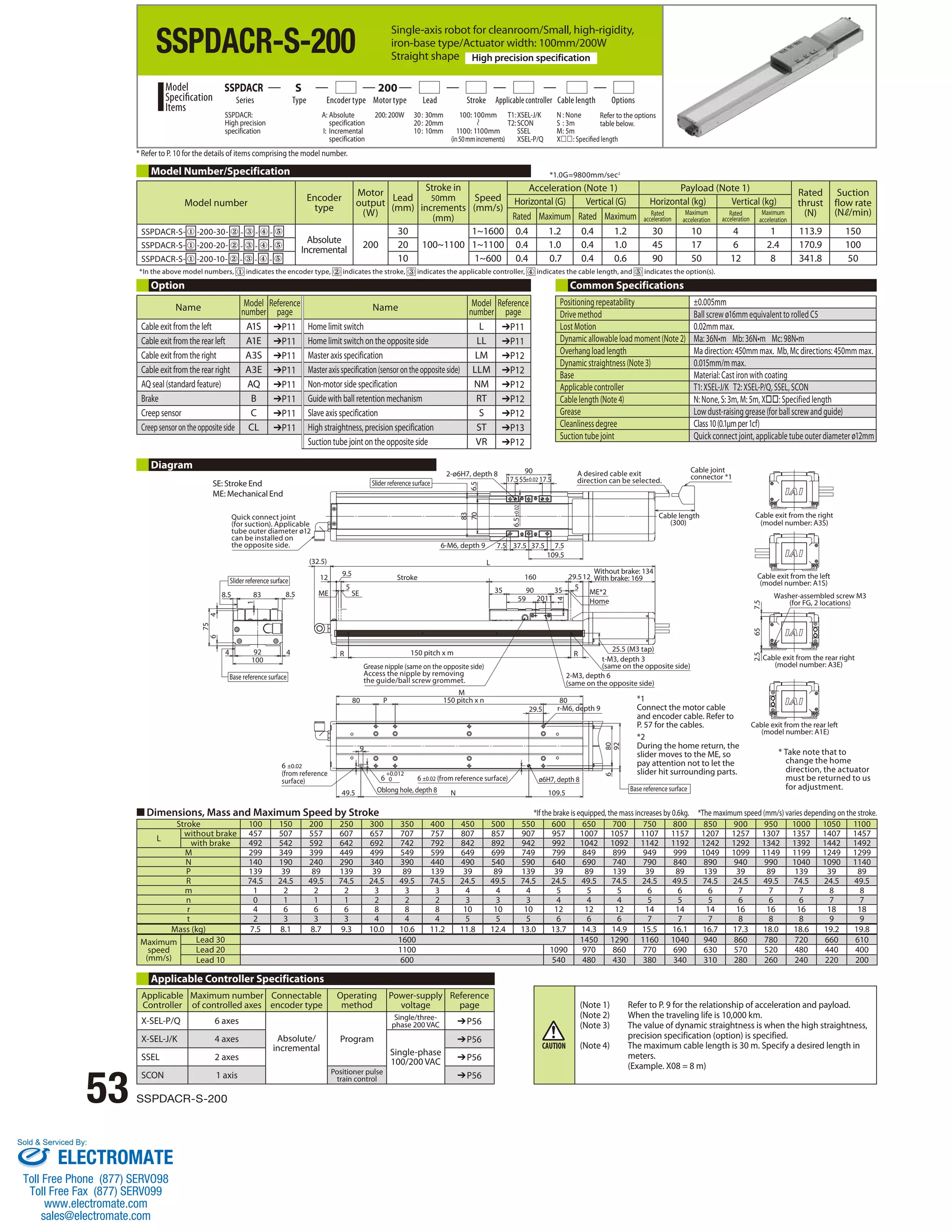
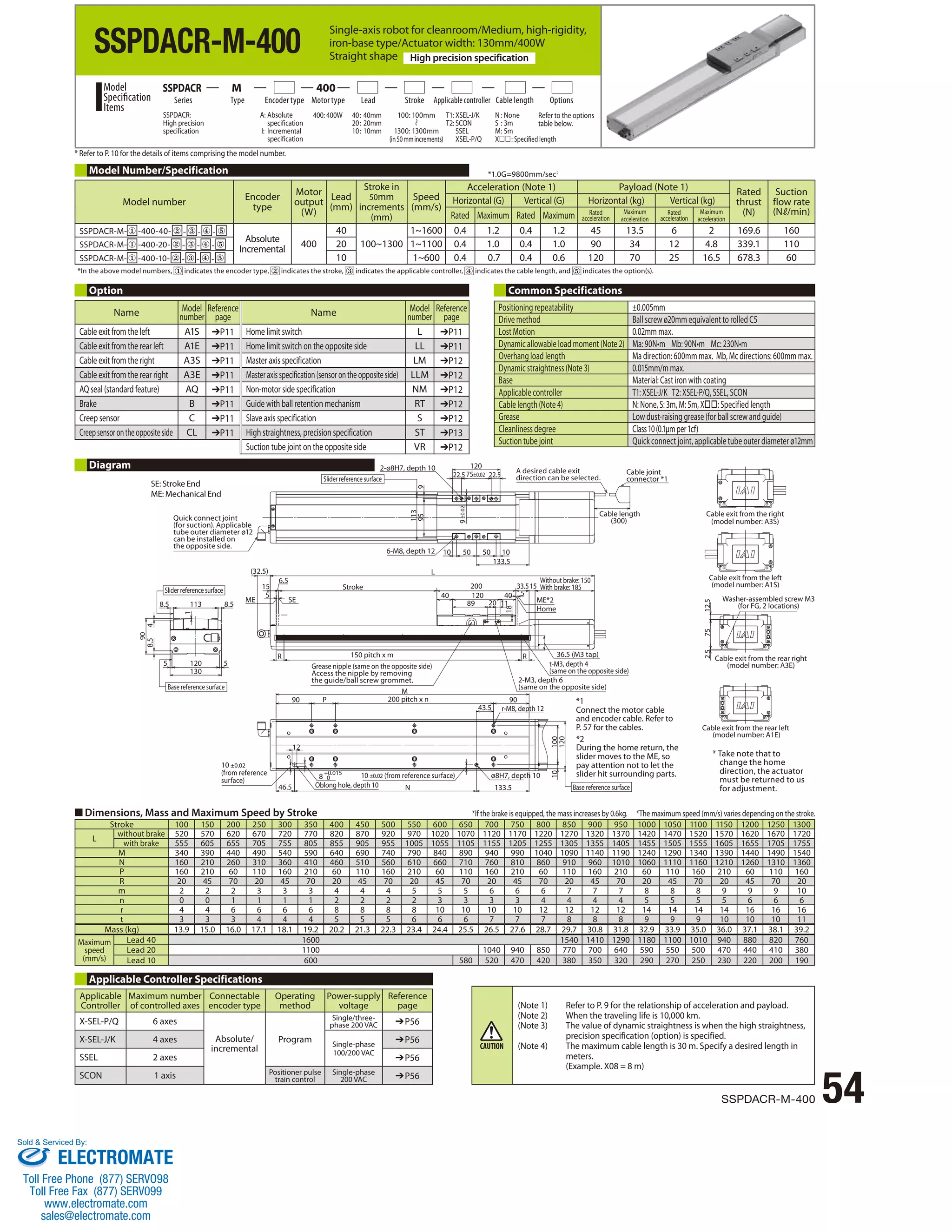
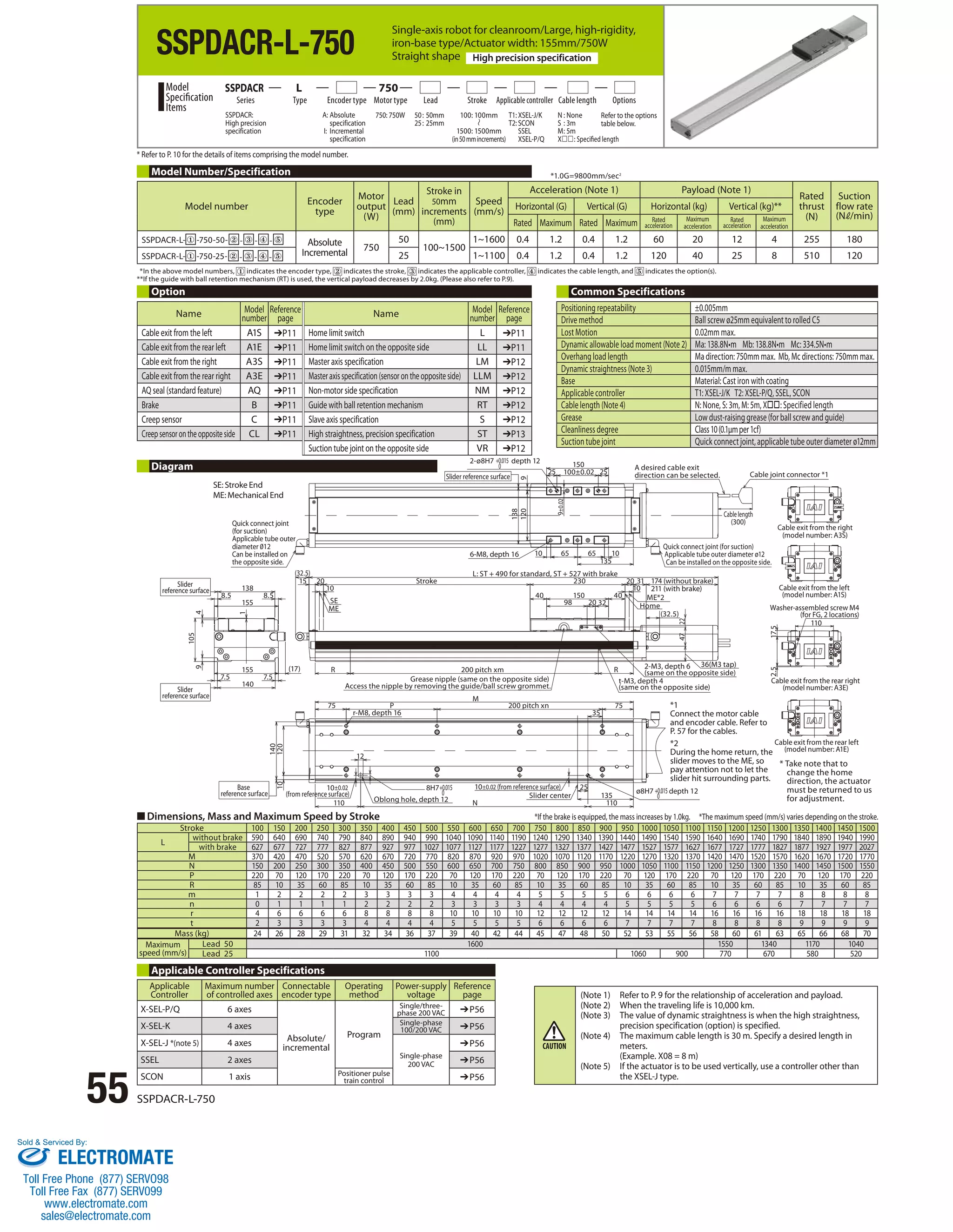
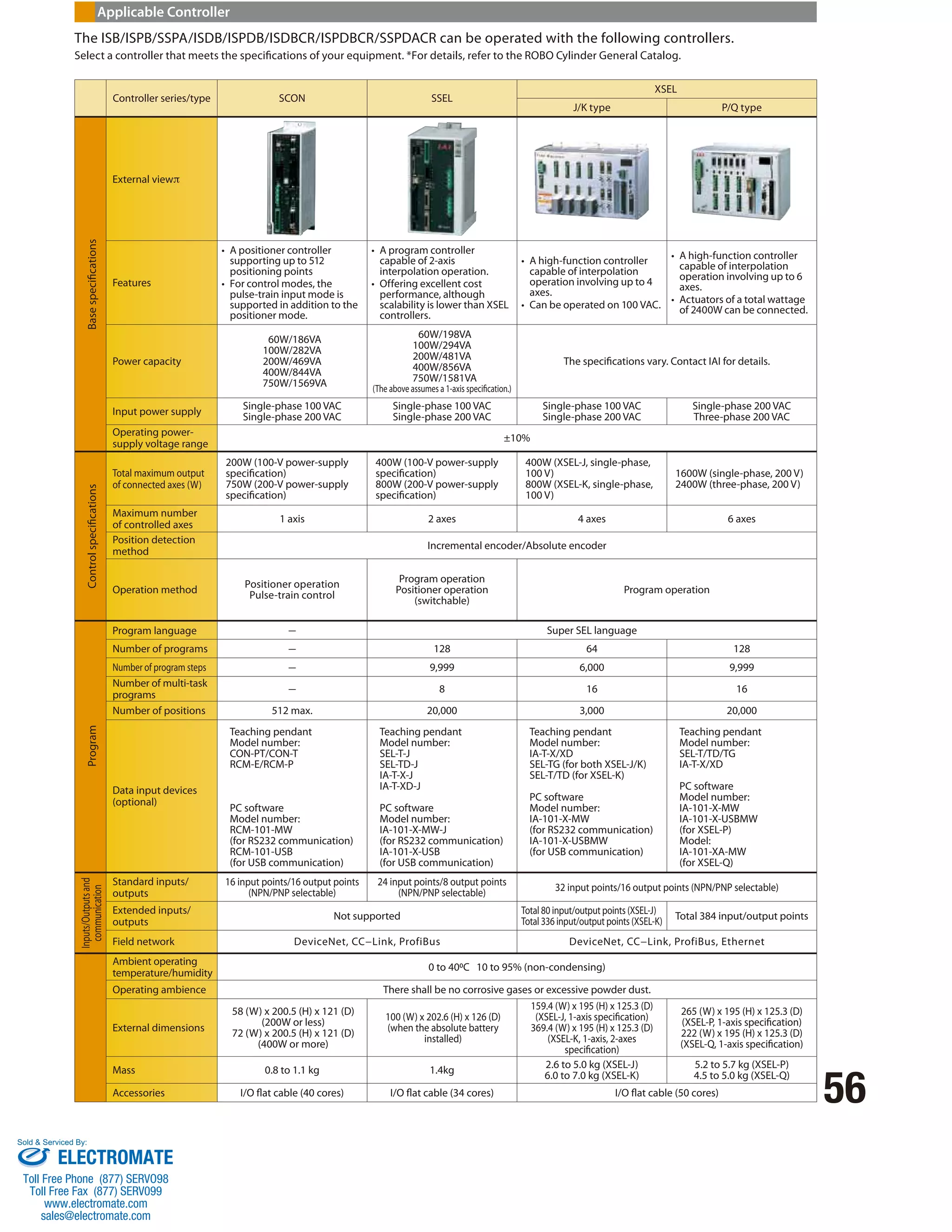
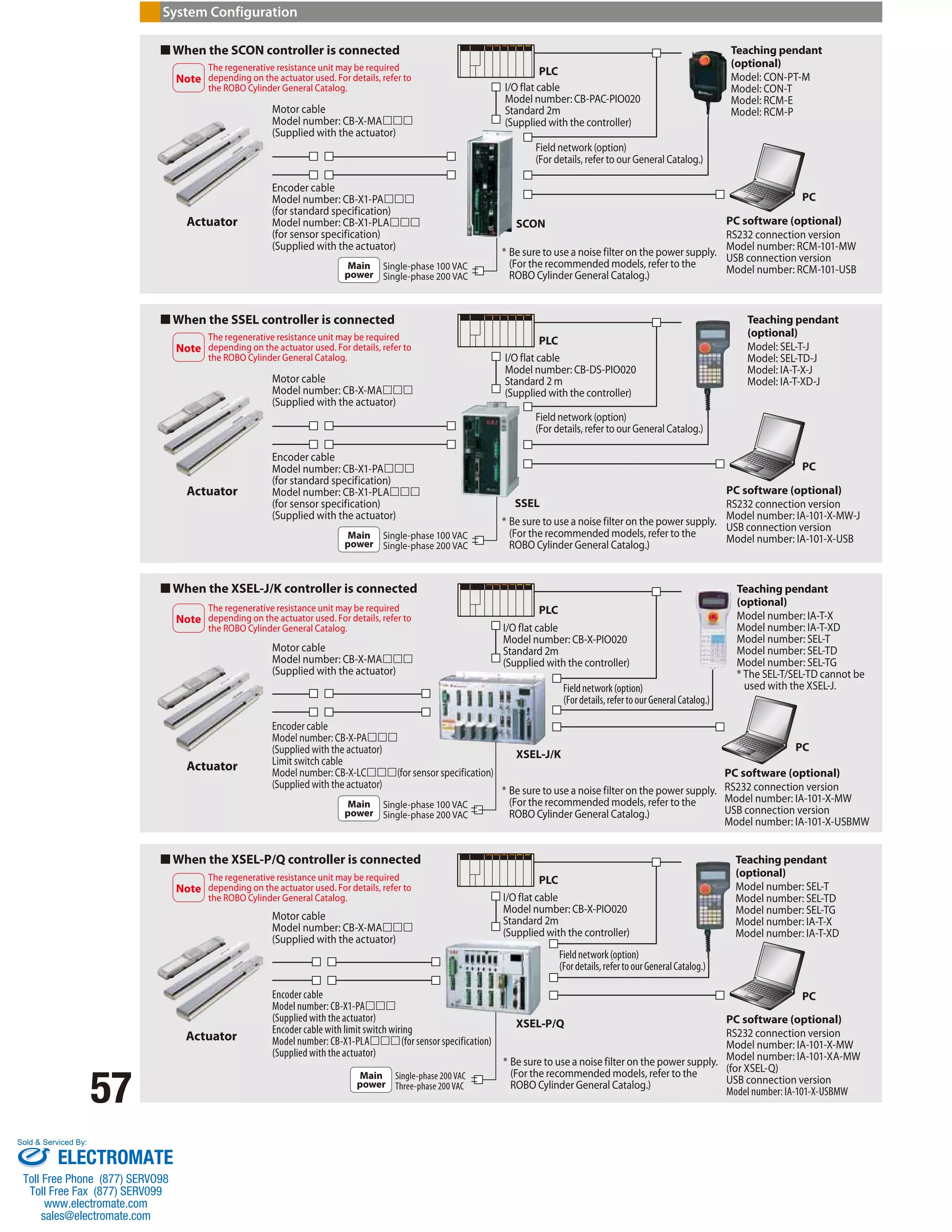

1. The document describes improvements made to the single-axis robot ISB/SSPA Series, including increased precision, rigidity, payload capacity, speed, and acceleration/deceleration. 2. New small and medium sizes have been added to the iron base SSPA Series. Performance has also been upgraded across models with higher payloads, longer stroke lengths, and increased speeds and accelerations. 3. The document provides specification details on the various series, including positioning repeatability, available sizes, strokes, motor outputs, ball screw leads, speeds, payloads, and allowable moments for each model.


![Vibe Coding vs. Spec-Driven Development [Free Meetup]](https://cdn.slidesharecdn.com/ss_thumbnails/vibecodingvsspecdrivendevelopment-251209105622-43f455e7-thumbnail.jpg?width=640&height=640&fit=bounds)