Download to read offline
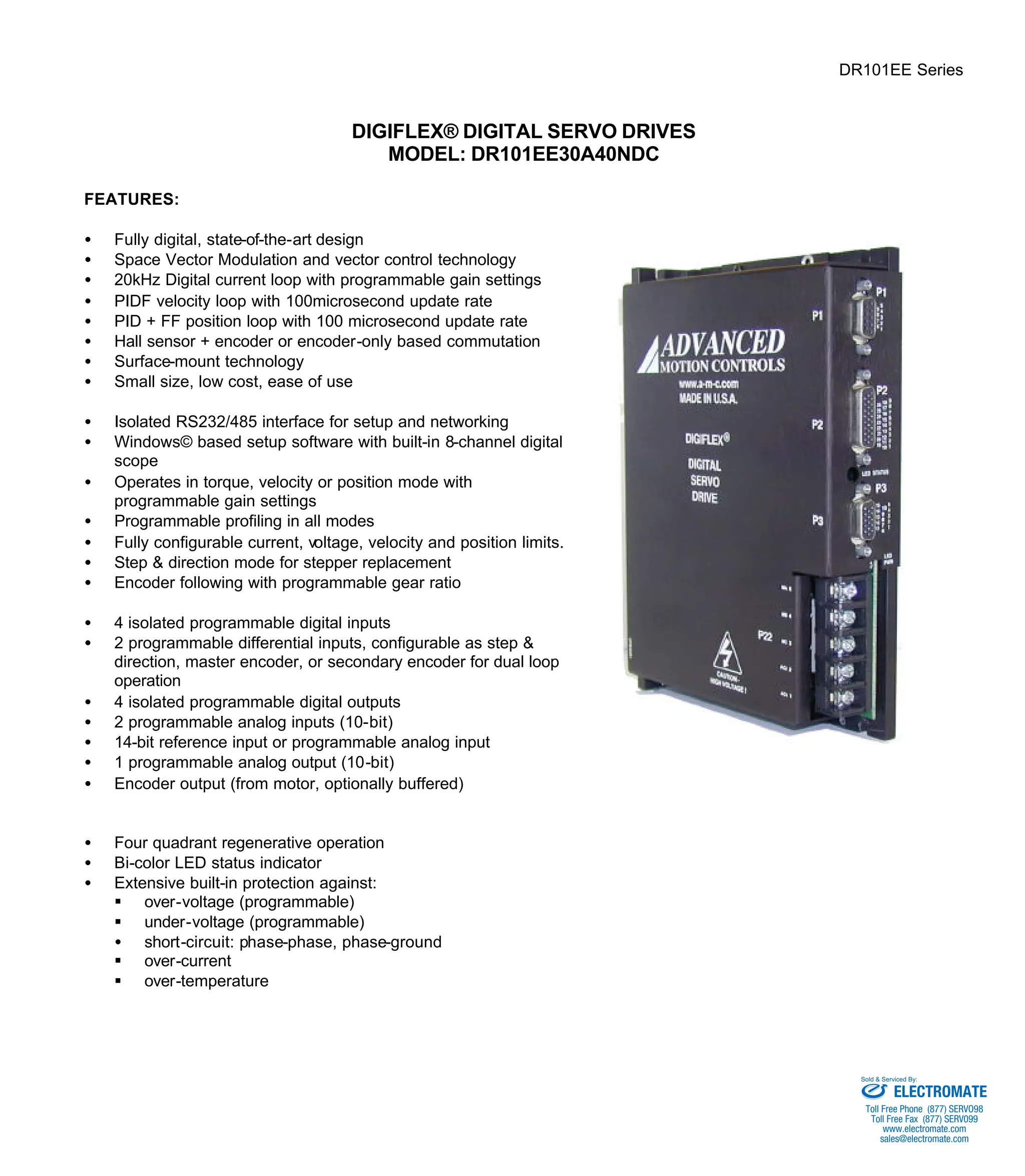
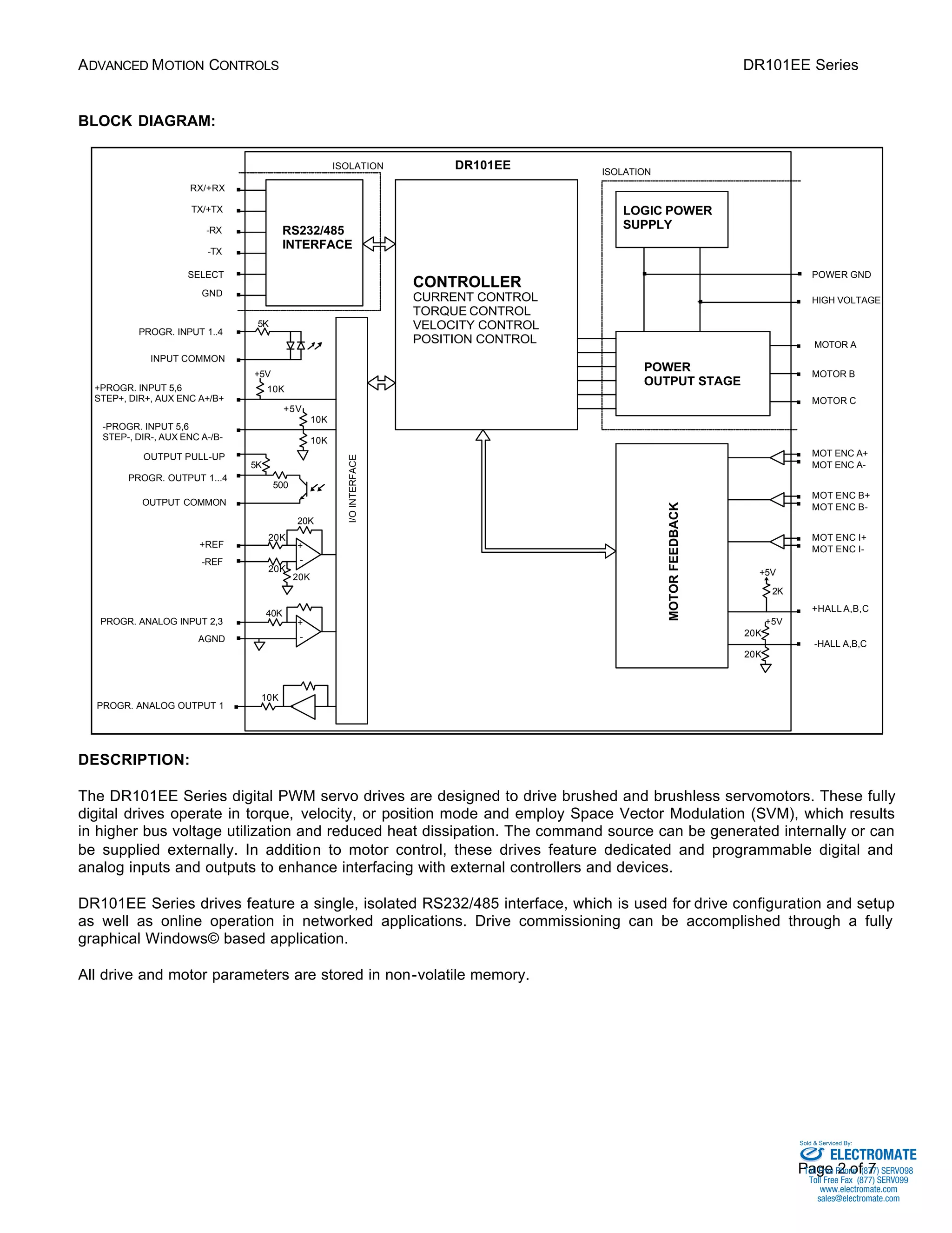
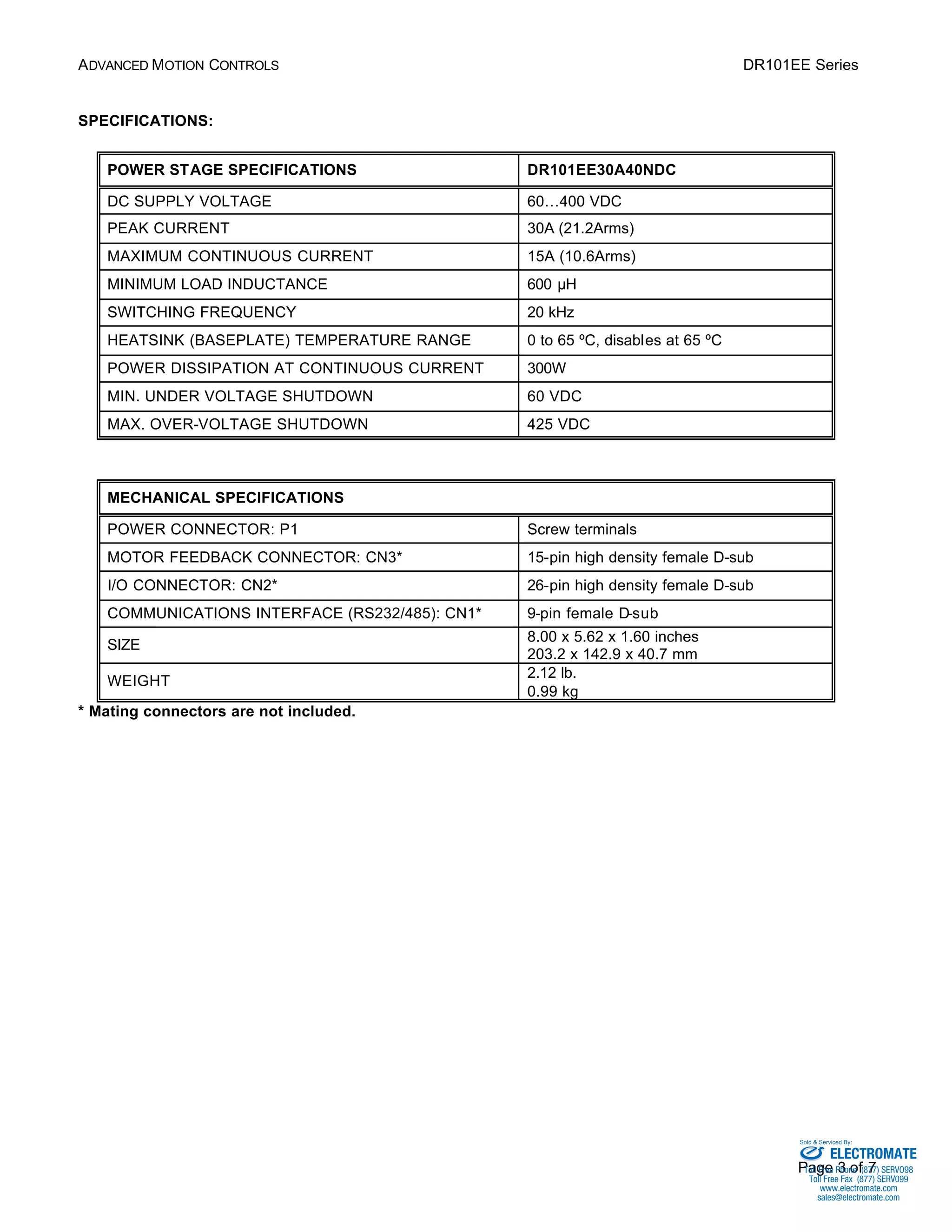
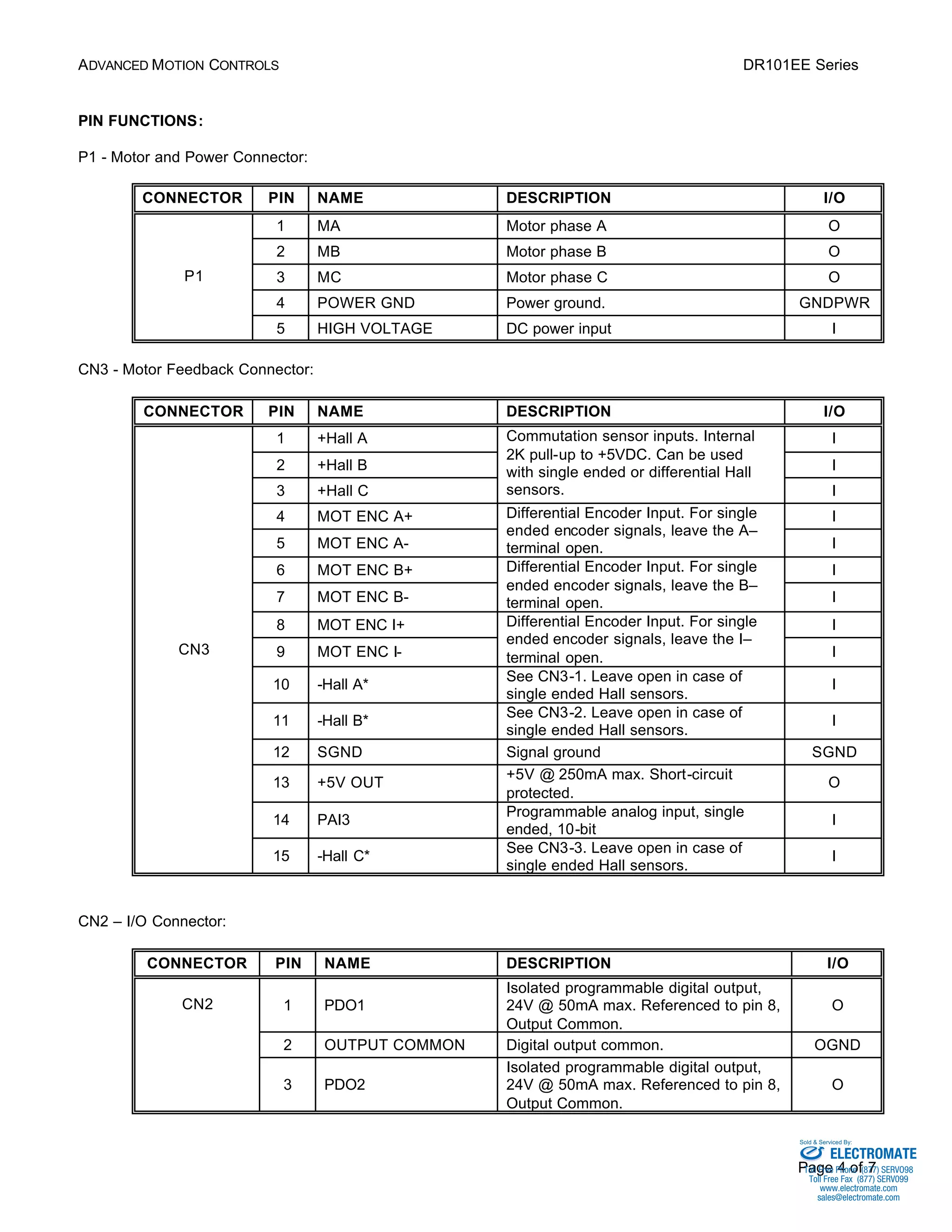

The DR101EE30A40NDC is a digital servo drive that controls brushed and brushless motors using space vector modulation. It operates in torque, velocity, or position mode and features programmable I/O, analog inputs and outputs, and a Windows-based setup software. The drive provides motor commutation and feedback, configurable protection features, and networked operation via an isolated RS232/485 interface.


