Download to read offline
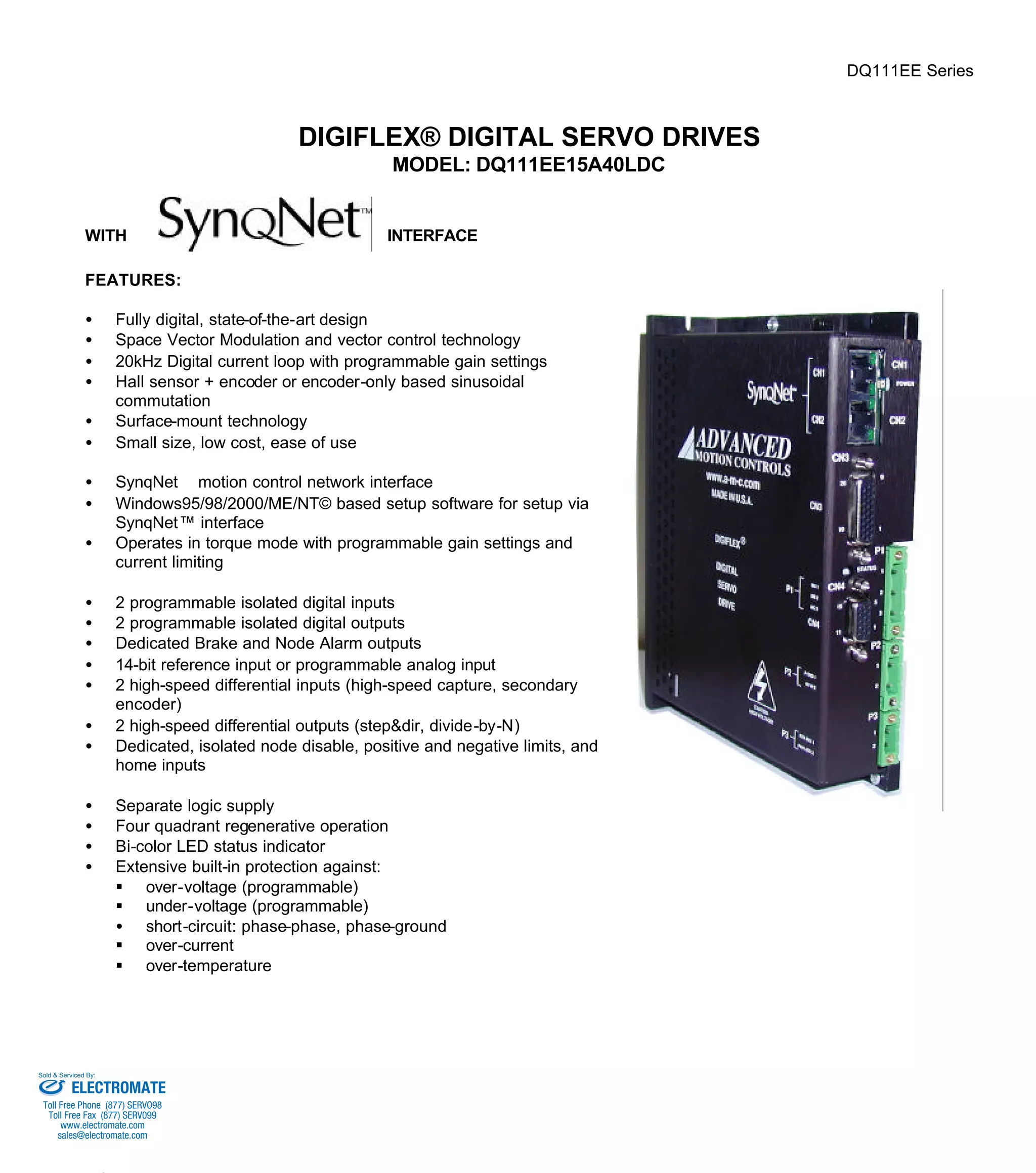
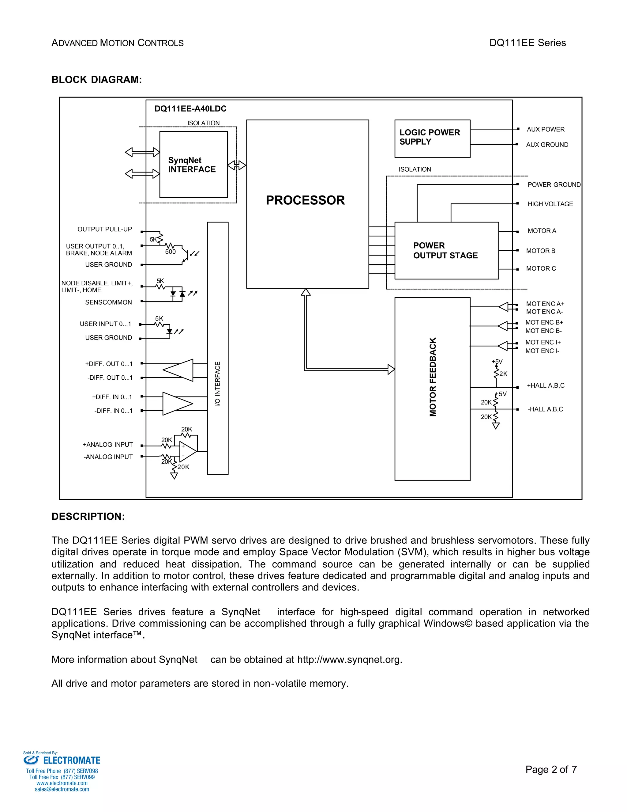

The DQ111EE15A40LDC is a digital servo drive that controls brushed and brushless motors. It features space vector modulation for high efficiency and integrated SynqNet interface for networked motion control applications. The drive provides torque control of the motor along with dedicated digital and analog inputs/outputs. It is designed for easy setup and commissioning through Windows-based software.


