Download to read offline
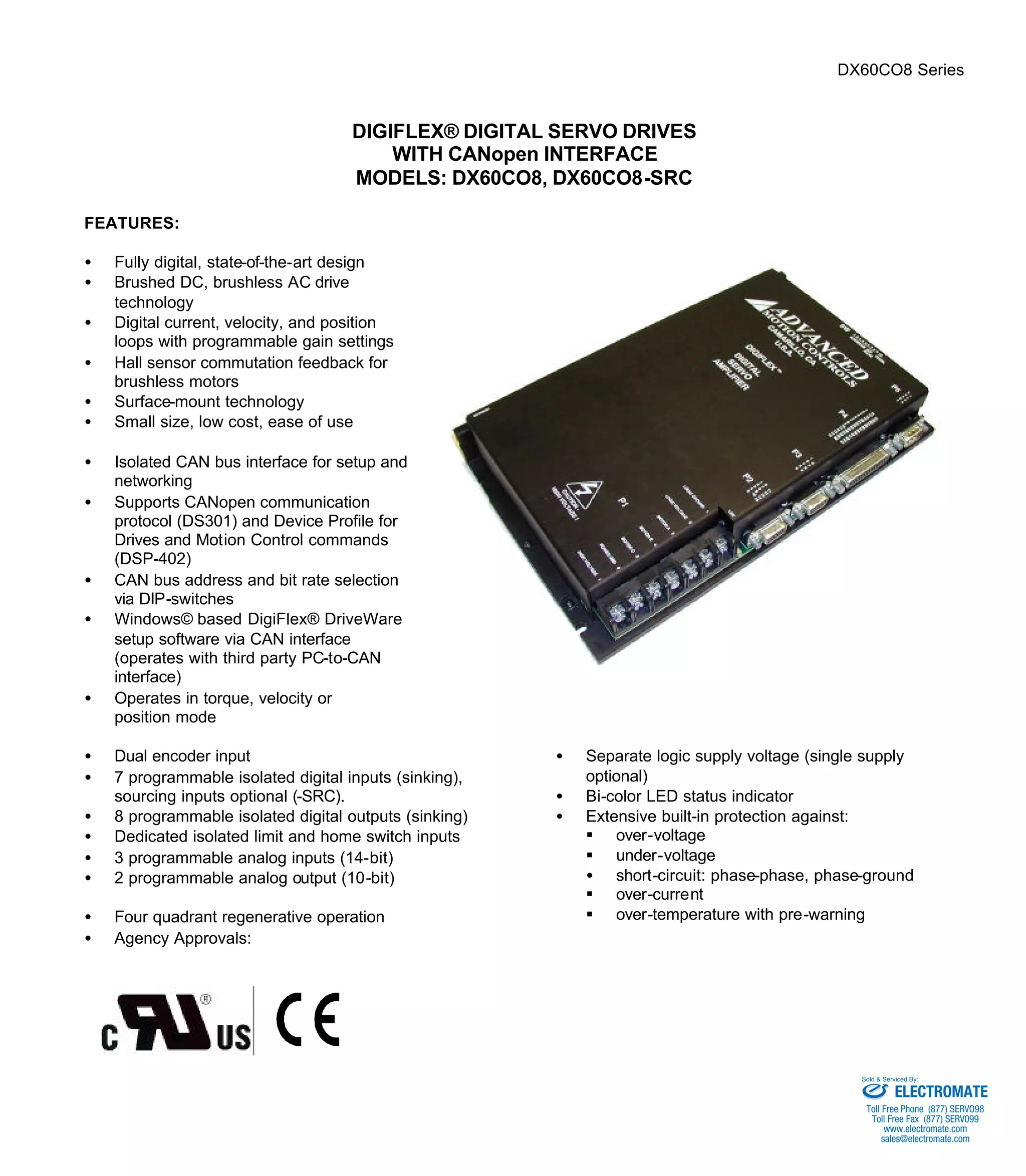
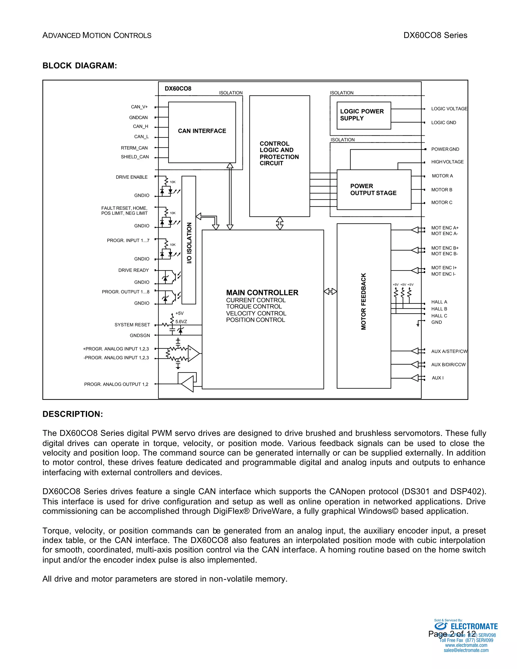
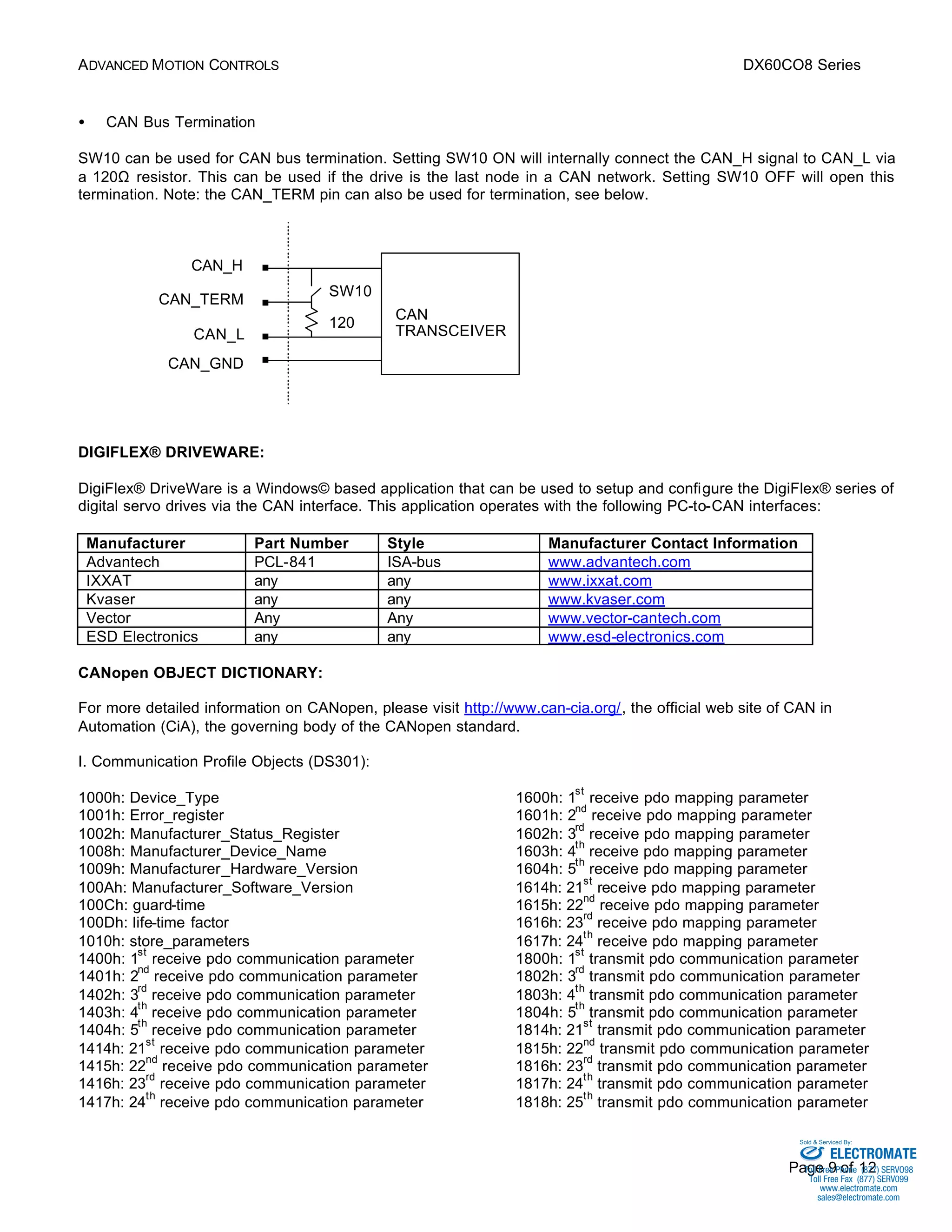

The DX60CO8 digital servo drive is designed to drive brushed and brushless motors. It features fully digital control loops, CANopen communication, and programmable I/O. Setup and configuration is done through DigiFlex DriveWare software via the isolated CAN interface, which supports DS301 and DSP402. The drive provides torque, velocity, or position control and integrated protection features.


![Coded Agents – with UiPath SDK + LangGraph [Virtual Hands-on Workshop]](https://cdn.slidesharecdn.com/ss_thumbnails/codedagentsdeck-251215155422-5497c599-thumbnail.jpg?width=640&height=640&fit=bounds)


