Download to read offline
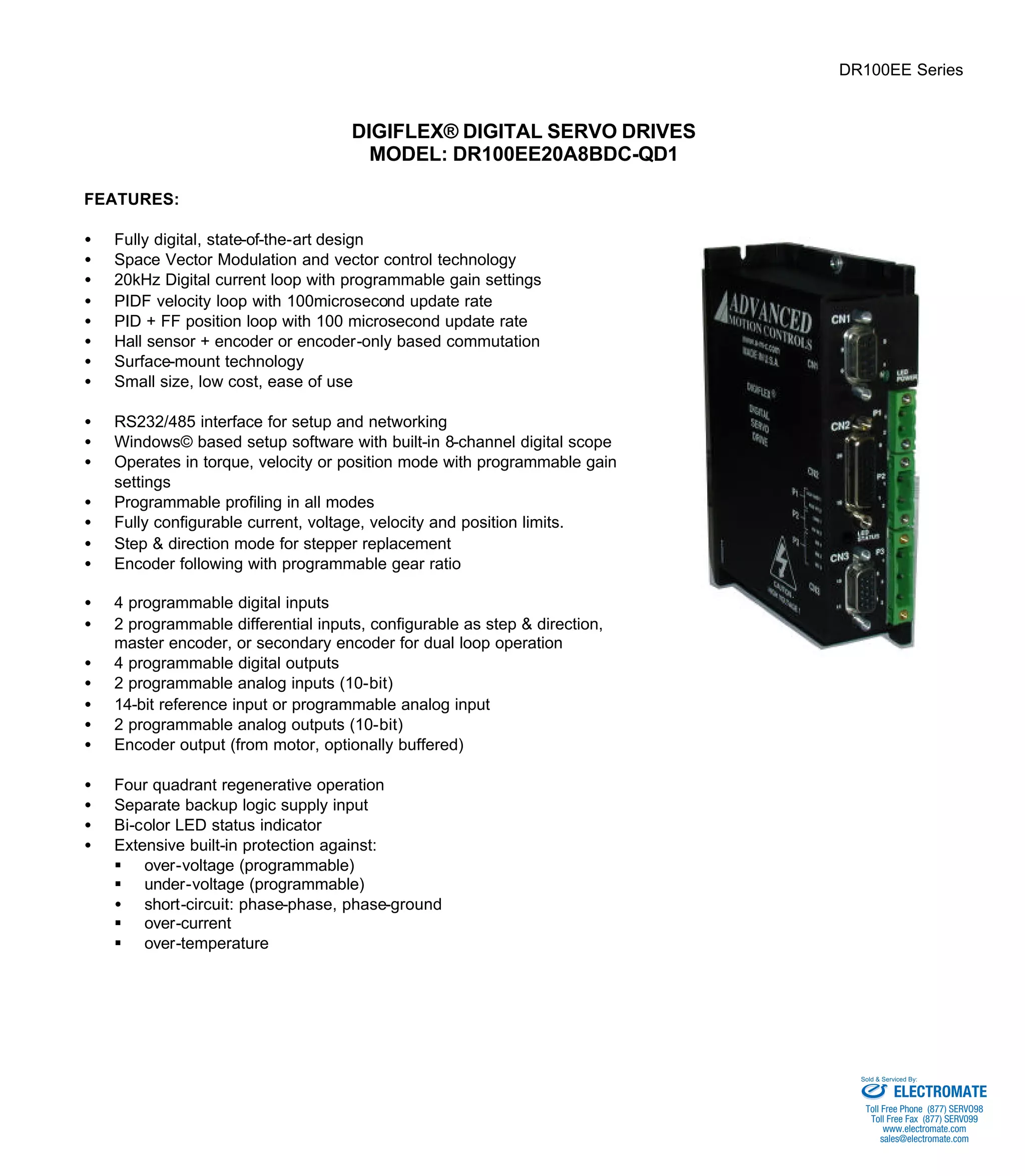
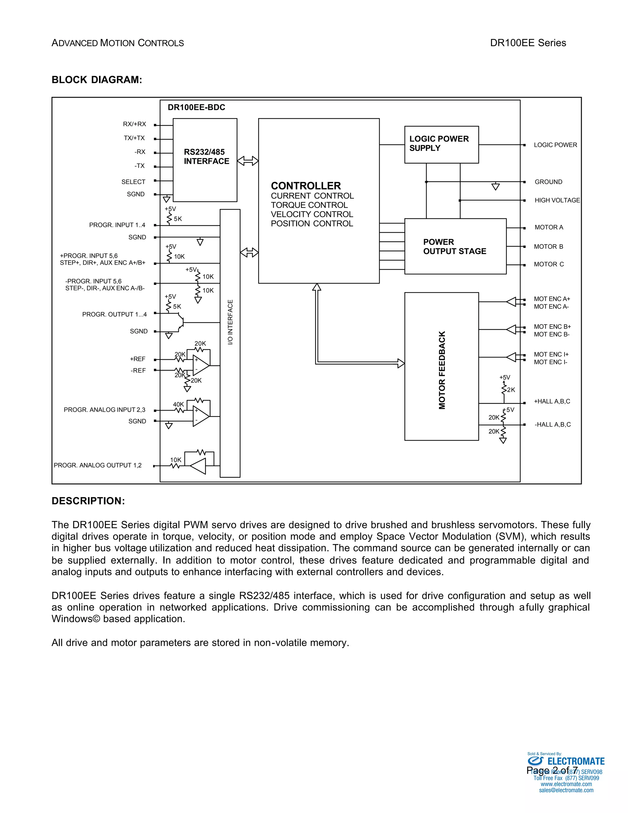
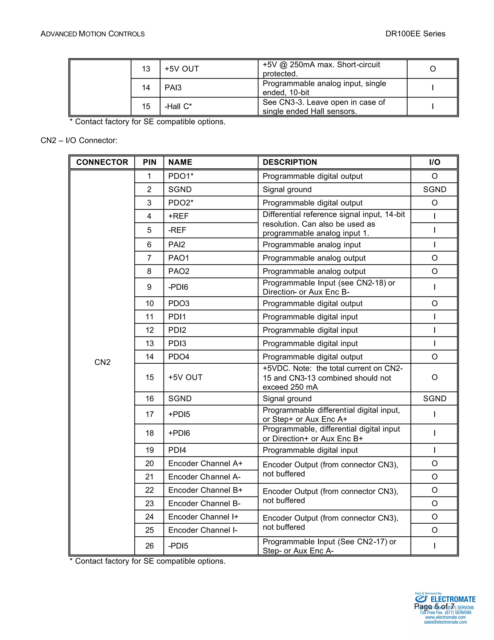
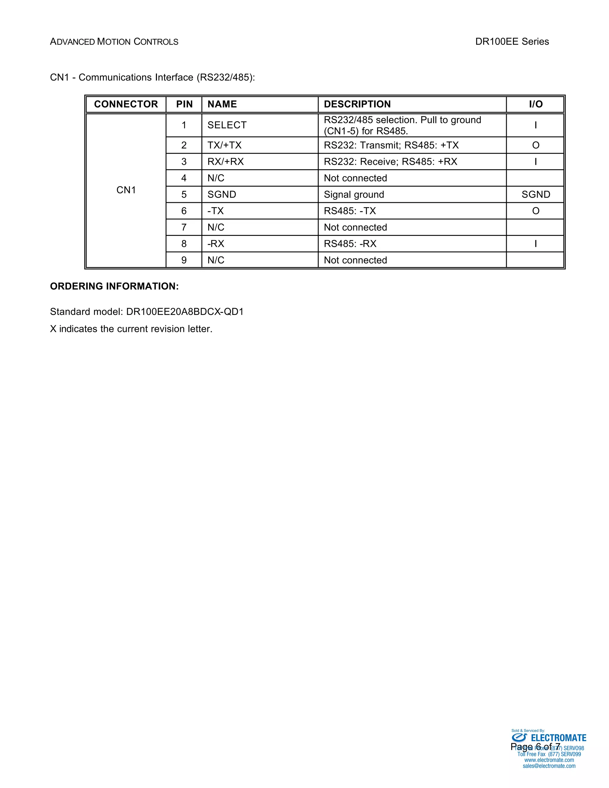

The DR100EE Series is a digital PWM servo drive designed to control brushed and brushless motors. It employs space vector modulation for high bus voltage utilization and low heat dissipation. The drive operates in torque, velocity, or position mode and features programmable digital and analog I/O for interfacing. It is configured through a Windows software and has RS-232/485 communication for setup and networking. The drive provides motor control, feedback processing, and protection in a small package.


![Coded Agents – with UiPath SDK + LangGraph [Virtual Hands-on Workshop]](https://cdn.slidesharecdn.com/ss_thumbnails/codedagentsdeck-251215155422-5497c599-thumbnail.jpg?width=640&height=640&fit=bounds)


![Vibe Coding vs. Spec-Driven Development [Free Meetup]](https://cdn.slidesharecdn.com/ss_thumbnails/vibecodingvsspecdrivendevelopment-251209105622-43f455e7-thumbnail.jpg?width=640&height=640&fit=bounds)


