Download to read offline
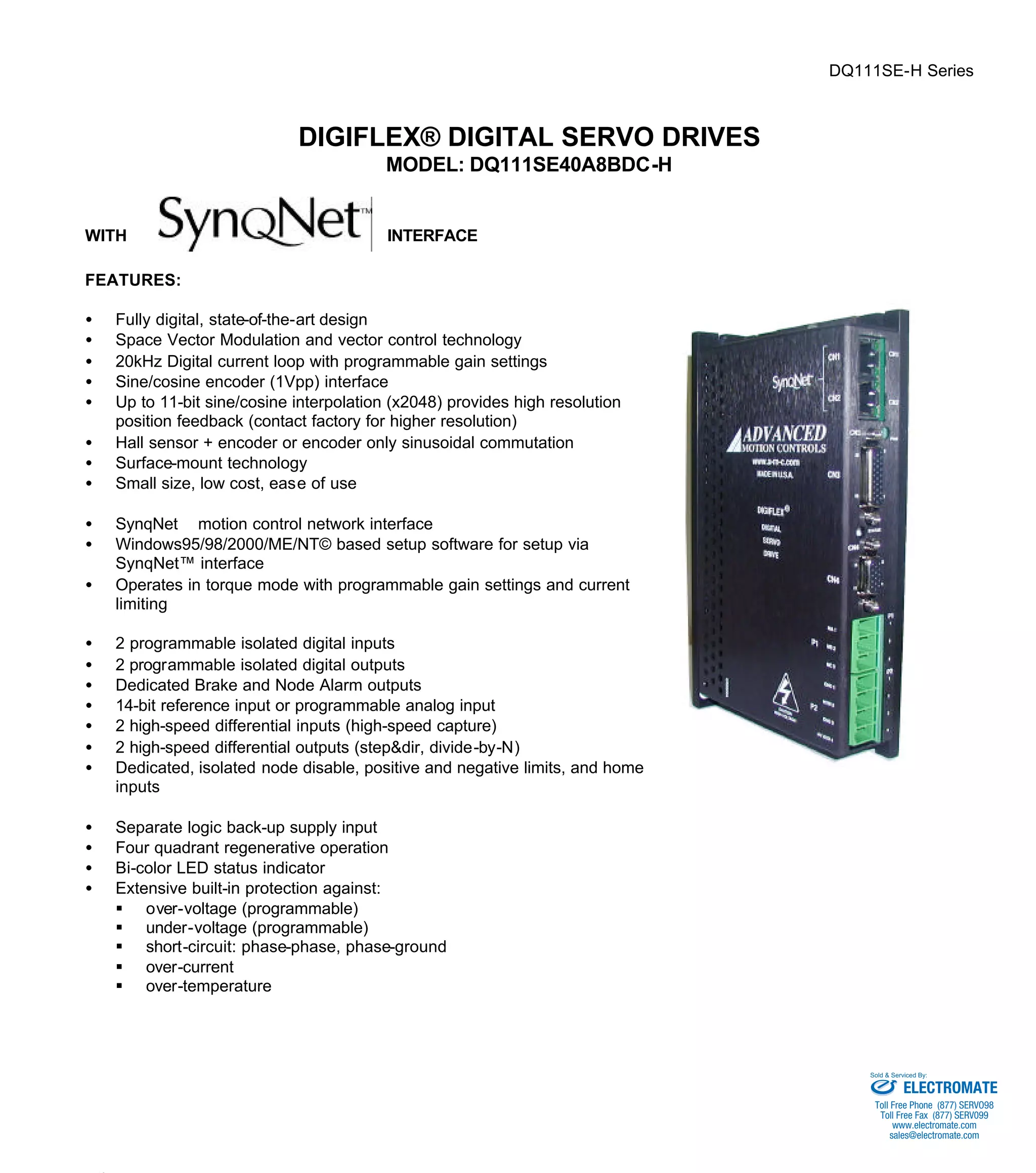
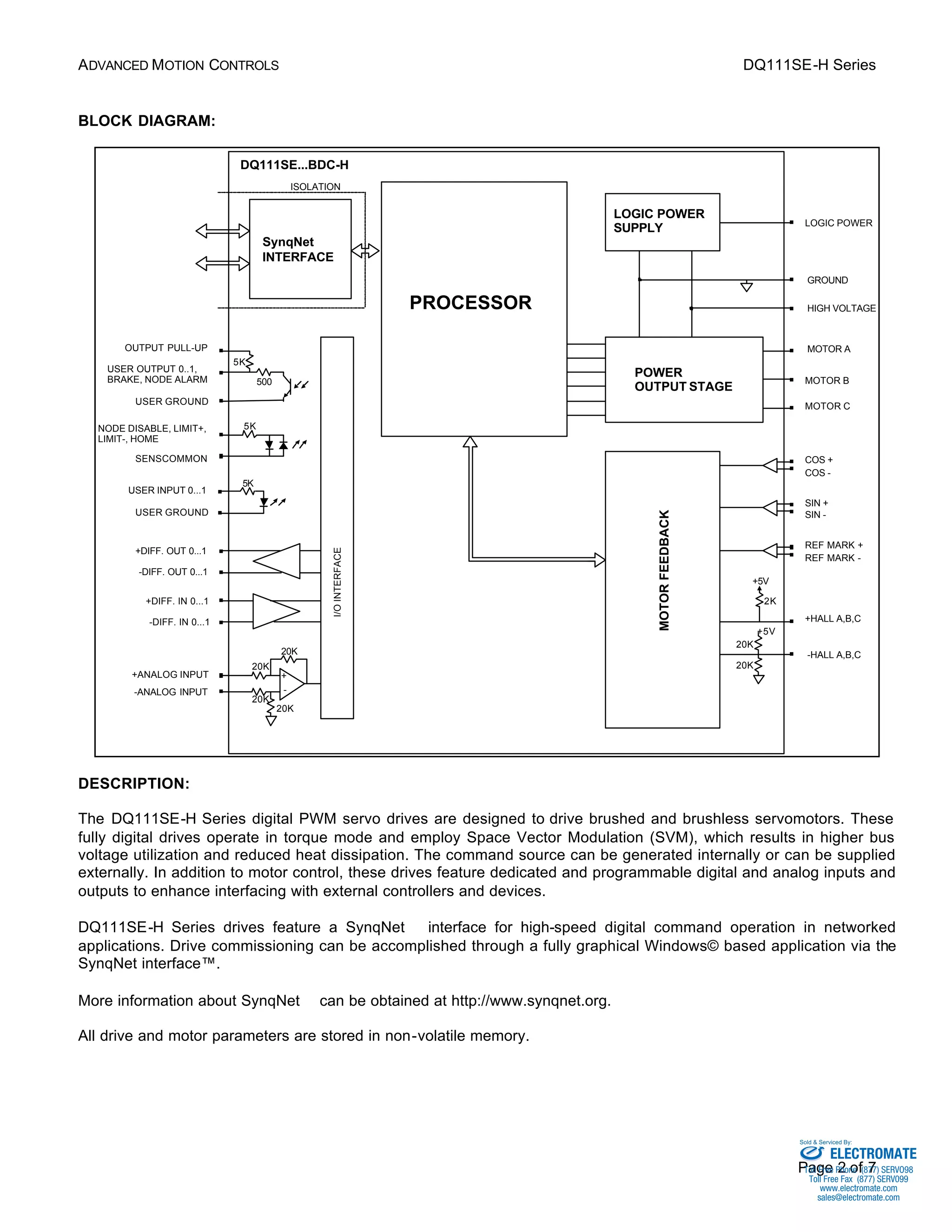

The DQ111SE-H Series digital servo drives are designed to drive brushed and brushless servomotors. They employ Space Vector Modulation and vector control technology to achieve high bus voltage utilization and reduced heat dissipation. The drives feature dedicated digital and analog inputs and outputs as well as a SynqNet interface for networked motion control applications.


