Advanced motion controls dr100ee40a8bdc
•
0 likes•138 views

The DR100EE40A8BDC is a digital servo drive that controls motors in torque, velocity, or position mode using space vector modulation. It has extensive I/O including digital and analog inputs and outputs. Setup and configuration is done through a Windows software over an RS232/485 interface.

Recommended
Recommended
More Related Content
What's hot
What's hot (20)
Viewers also liked
Viewers also liked (11)
Similar to Advanced motion controls dr100ee40a8bdc
Similar to Advanced motion controls dr100ee40a8bdc (11)
More from Electromate
More from Electromate (20)
Recently uploaded
Recently uploaded (20)
Advanced motion controls dr100ee40a8bdc
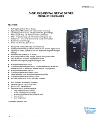
- 1. DR100EE Series DIGIFLEX® DIGITAL SERVO DRIVES MODEL: DR100EE40A8BDC FEATURES: · Fully digital, state-of-the-art design · Space Vector Modulation and vector control technology · 20kHz Digital current loop with programmable gain settings · PIDF velocity loop with 100microsecond update rate · PID + FF position loop with 100 microsecond update rate · Hall sensor + encoder or encoder-only based commutation · Surface-mount technology · Small size, low cost, ease of use · RS232/485 interface for setup and networking · Windows© based setup software with built-in 8-channel digital scope · Operates in torque, velocity or position mode with programmable gain settings · Programmable profiling in all modes · Fully configurable current, voltage, velocity and position limits. · Step & direction mode for stepper replacement · Encoder following with programmable gear ratio · 4 programmable digital inputs · 2 programmable differential inputs, configurable as step & direction, master encoder, or secondary encoder for dual loop operation · 4 programmable digital outputs · 2 programmable analog inputs (10-bit) · 14-bit reference input or programmable analog input · 2 programmable analog outputs (10-bit) · Encoder output (from motor, optionally buffered) · Four quadrant regenerative operation · Separate backup logic supply input · Bi-color LED status indicator · Extensive built-in protection against: § over-voltage (programmable) § under-voltage (programmable) · short-circuit: phase-phase, phase-ground § over-current § over-temperature *Picture for reference only. ADVANCED MOTION CONTROLS Sold & Serviced By: ELECTROMATE Toll Free Phone (877) SERVO98 Toll Free Fax (877) SERV099 www.electromate.com sales@electromate.com
- 2. ADVANCED MOTION CONTROLS DR100EE Series LOGIC POWER GROUND MOT ENC A+ MOT ENC A-MOT ENC B+ MOT ENC B-MOT ENC I+ MOT ENC I-RS232/ Sold & Serviced By: Page 2 of 7 BLOCK DIAGRAM: MOTOR A MOTOR B MOTOR C RX/+RX LOGIC POWER SUPPLY -RX -TX 5K 10K 10K 20K 10K 20K 2K 5K 20K 20K 20K 40K 10K - 20K +5V SELECT SGND PROGR. OUTPUT 1...4 SGND +REF -REF PROGR. ANALOG INPUT 2,3 SGND PROGR. ANALOG OUTPUT 1,2 +HALL A,B,C -HALL A,B,C 485 INTERFACE MOTOR FEEDBACK + + - TX/+TX SGND HIGH VOLTAGE POWER OUTPUT STAGE PROGR. INPUT 1..4 DR100EE-BDC +5V +5V +5V +5V +5V I/O INTERFACE +PROGR. INPUT 5,6 STEP+, DIR+, AUX ENC A+/B+ -PROGR. INPUT 5,6 STEP-, DIR-, AUX ENC A-/B-CONTROLLER CURRENT CONTROL TORQUE CONTROL VELOCITY CONTROL POSITION CONTROL DESCRIPTION: The DR100EE Series digital PWM servo drives are designed to drive brushed and brushless servomotors. These fully digital drives operate in torque, velocity, or position mode and employ Space Vector Modulation (SVM), which results in higher bus voltage utilization and reduced heat dissipation. The command source can be generated internally or can be supplied externally. In addition to motor control, these drives feature dedicated and programmable digital and analog inputs and outputs to enhance interfacing with external controllers and devices. DR100EE Series drives feature a single RS232/485 interface, which is used for drive configuration and setup as well as online operation in networked applications. Drive commissioning can be accomplished through a fully graphical Windows© based application. All drive and motor parameters are stored in non-volatile memory. ELECTROMATE Toll Free Phone (877) SERVO98 Toll Free Fax (877) SERV099 www.electromate.com sales@electromate.com
- 3. ADVANCED MOTION CONTROLS DR100EE Series Sold & Serviced By: Page 3 of 7 SPECIFICATIONS: POWER STAGE SPECIFICATIONS DR100EE40A8BDC DC SUPPLY VOLTAGE 20…80 VDC PEAK CURRENT 40A (28.3Arms) MAXIMUM CONTINUOUS CURRENT 20A (14.2Arms) MINIMUM LOAD INDUCTANCE 250 μH SWITCHING FREQUENCY 20 kHz HEATSINK (BASEPLATE) TEMPERATURE RANGE 0 to 65 ºC, disables at 65 ºC POWER DISSIPATION AT CONTINUOUS CURRENT 100W MIN. UNDER VOLTAGE SHUTDOWN 20 VDC MAX. OVER-VOLTAGE SHUTDOWN 86 VDC LOGIC SUPPLY VOLTAGE (backup supply) 20…80 VDC, 20W maximum MECHANICAL SPECIFICATIONS MOTOR CONNECTOR: P1 Removable screw terminal POWER CONNECTOR: P2 Removable screw terminal MOTOR FEEDBACK CONNECTOR: CN3* 15-pin high density female D-sub I/O CONNECTOR: CN2* 26-pin high density female D-sub COMMUNICATIONS INTERFACE (RS232/485): CN1* 9-pin female D-sub SIZE 7.50 x 4.40 x 1.41 inches 190.5 x 111.8 x 35.9 mm WEIGHT * Mating connectors are not included. ELECTROMATE Toll Free Phone (877) SERVO98 Toll Free Fax (877) SERV099 www.electromate.com sales@electromate.com
- 4. ADVANCED MOTION CONTROLS DR100EE Series Commutation sensor inputs. Internal 2K pull-up to +5VDC. Can be used with single ended or differential Hall sensors. I Sold & Serviced By: Page 4 of 7 PIN FUNCTIONS: P1 - Motor Connector: CONNECTOR PIN NAME DESCRIPTION I/O 1 MA Motor phase A O P1 2 MB Motor phase B O 3 MC Motor phase C O P2 - Power Connector: CONNECTOR PIN NAME DESCRIPTION I/O 1 GND Ground GND 2 HV IN DC motor and power input. This input is used to supply power to the motor and drive logic circuitry. I P2 3 GND Ground GND 4 HV AUX Logic supply input. This input can be used to supply power to the drive logic circuitry only. Effective only when the voltage applied to pin P2-2 is lower then the voltage applied to P2-4. I CN3 - Motor Feedback Connector: CONNECTOR PIN NAME DESCRIPTION I/O 1 +Hall A I 2 +Hall B I 3 +Hall C Encoder Input. For single 4 MOT ENC A+ I 5 MOT ENC A-Differential ended encoder signals, leave the A– terminal open. I Encoder Input. For single 6 MOT ENC B+ I 7 MOT ENC B-Differential ended encoder signals, leave the B– terminal open. I Encoder Input. For single 8 MOT ENC I+ I 9 MOT ENC I-Differential ended encoder signals, leave the I– terminal open. I 10 -Hall A* See CN3-1. Leave open in case of single ended Hall sensors. I 11 -Hall B* See CN3-2. Leave open in case of single ended Hall sensors. I 12 SGND Signal ground SGND 13 +5V OUT +5V @ 250mA max. Short-circuit protected. O CN3 14 PAI3 Programmable analog input, single ended, 10-bit I ELECTROMATE Toll Free Phone (877) SERVO98 Toll Free Fax (877) SERV099 www.electromate.com sales@electromate.com
- 5. ADVANCED MOTION CONTROLS DR100EE Series Sold & Serviced By: Page 5 of 7 15 -Hall C* See CN3-3. Leave open in case of single ended Hall sensors. I * Contact factory for SE compatible options. CN2 – I/O Connector: CONNECTOR PIN NAME DESCRIPTION I/O 1 PDO1* Programmable digital output O 2 SGND Signal ground SGND 3 PDO2* Programmable digital output O 4 +REF I 5 -REF Differential reference signal input, 14-bit resolution. Can also be used as programmable analog input 1. I 6 PAI2 Programmable analog input I 7 PAO1 Programmable analog output O 8 PAO2 Programmable analog output O 9 -PDI6 Programmable Input (see CN2-18) or Direction- or Aux Enc B-I 10 PDO3 Programmable digital output O 11 PDI1 Programmable digital input I 12 PDI2 Programmable digital input I 13 PDI3 Programmable digital input I 14 PDO4 Programmable digital output O 15 +5V OUT +5VDC. Note: the total current on CN2- 15 and CN3-13 combined should not exceed 250 mA O 16 SGND Signal ground SGND 17 +PDI5 Programmable differential digital input, or Step+ or Aux Enc A+ I 18 +PDI6 Programmable, differential digital input or Direction+ or Aux Enc B+ I 19 PDI4 Programmable digital input I 20 Encoder Channel A+ Output (from connector CN3), O 21 Encoder Channel A-Encoder not buffered O 22 Encoder Channel B+ Output (from connector CN3), O 23 Encoder Channel B-Encoder not buffered O 24 Encoder Channel I+ Output (from connector CN3), O 25 Encoder Channel I-Encoder not buffered O CN2 26 -PDI5 Programmable Input (See CN2-17) or Step- or Aux Enc A-I * Contact factory for SE compatible options. CN1 - Communications Interface (RS232/485): ELECTROMATE Toll Free Phone (877) SERVO98 Toll Free Fax (877) SERV099 www.electromate.com sales@electromate.com
- 6. ADVANCED MOTION CONTROLS DR100EE Series CONNECTOR PIN NAME DESCRIPTION I/O Sold & Serviced By: Page 6 of 7 1 SELECT RS232/485 selection. Pull to ground (CN1-5) for RS485. I 2 TX/+TX RS232: Transmit; RS485: +TX O 3 RX/+RX RS232: Receive; RS485: +RX I 4 N/C Not connected 5 SGND Signal ground SGND 6 -TX RS485: -TX O 7 N/C Not connected 8 -RX RS485: -RX I CN1 9 N/C Not connected ORDERING INFORMATION: Standard model: DR100EE40A8BDCX X indicates the current revision letter. ELECTROMATE Toll Free Phone (877) SERVO98 Toll Free Fax (877) SERV099 www.electromate.com sales@electromate.com
- 7. ADVANCED MOTION CONTROLS DR100EE Series Sold & Serviced By: Page 7 of 7 MOUNTING DIMENSIONS: ELECTROMATE Toll Free Phone (877) SERVO98 Toll Free Fax (877) SERV099 www.electromate.com sales@electromate.com