Download to read offline
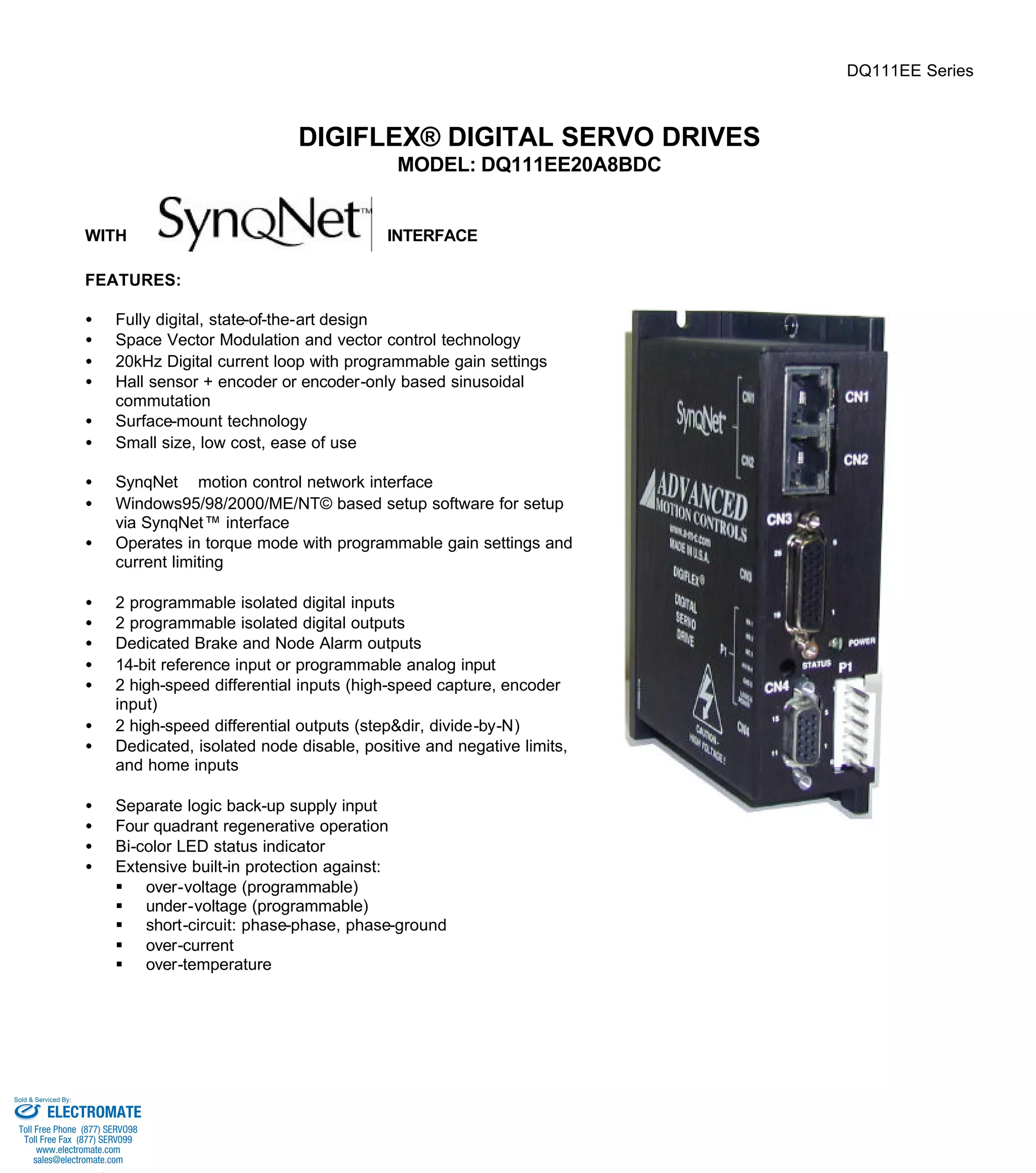
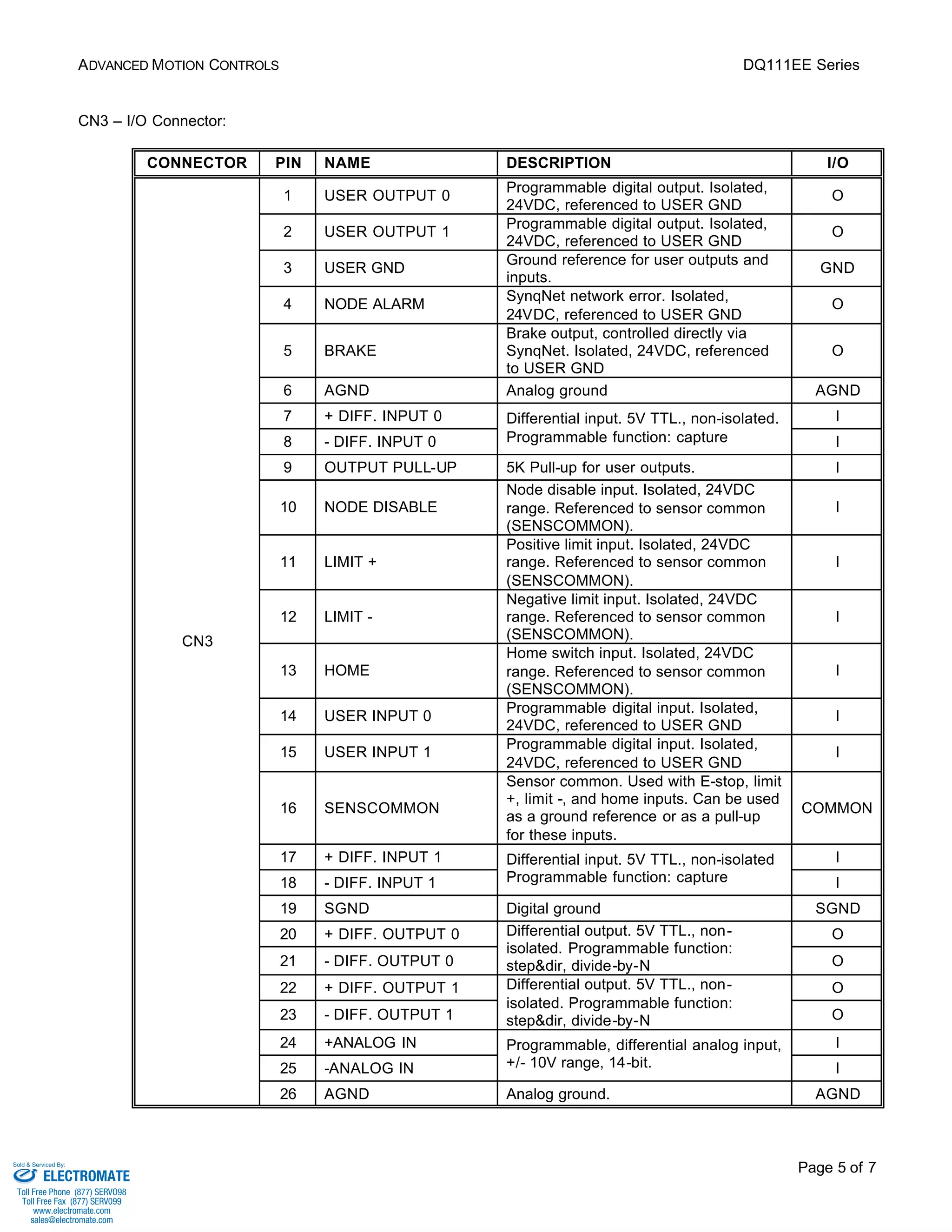
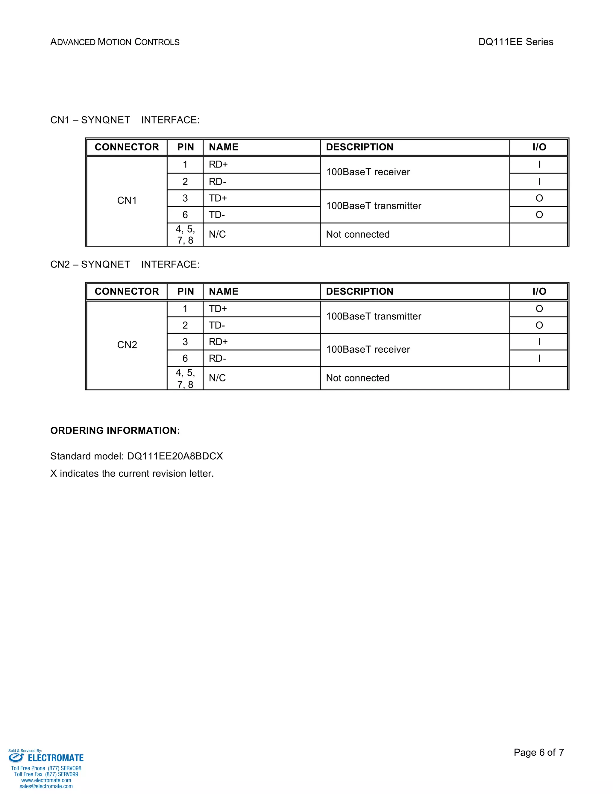

The DQ111EE Series is a digital servo drive that controls brushed and brushless motors. It features state-of-the-art digital control, space vector modulation, and a SynqNet interface for networked motion control applications. The drive provides motor commutation, I/O, and protection from overvoltage, undervoltage, and overcurrent. It is designed for ease of use and setup via Windows software.


