Connector Corner: Automate dynamic content and events by pushing a buttonDianaGray10
Here is something new! In our next Connector Corner webinar, we will demonstrate how you can use a single workflow to:
Create a campaign using Mailchimp with merge tags/fields
Send an interactive Slack channel message (using buttons)
Have the message received by managers and peers along with a test email for review
But there’s more:
In a second workflow supporting the same use case, you’ll see:
Your campaign sent to target colleagues for approval
If the “Approve” button is clicked, a Jira/Zendesk ticket is created for the marketing design team
But—if the “Reject” button is pushed, colleagues will be alerted via Slack message
Join us to learn more about this new, human-in-the-loop capability, brought to you by Integration Service connectors.
And...
Speakers:
Akshay Agnihotri, Product Manager
Charlie Greenberg, Host
GDG Cloud Southlake #33: Boule & Rebala: Effective AppSec in SDLC using Deplo...James Anderson
Effective Application Security in Software Delivery lifecycle using Deployment Firewall and DBOM
The modern software delivery process (or the CI/CD process) includes many tools, distributed teams, open-source code, and cloud platforms. Constant focus on speed to release software to market, along with the traditional slow and manual security checks has caused gaps in continuous security as an important piece in the software supply chain. Today organizations feel more susceptible to external and internal cyber threats due to the vast attack surface in their applications supply chain and the lack of end-to-end governance and risk management.
The software team must secure its software delivery process to avoid vulnerability and security breaches. This needs to be achieved with existing tool chains and without extensive rework of the delivery processes. This talk will present strategies and techniques for providing visibility into the true risk of the existing vulnerabilities, preventing the introduction of security issues in the software, resolving vulnerabilities in production environments quickly, and capturing the deployment bill of materials (DBOM).
Speakers:
Bob Boule
Robert Boule is a technology enthusiast with PASSION for technology and making things work along with a knack for helping others understand how things work. He comes with around 20 years of solution engineering experience in application security, software continuous delivery, and SaaS platforms. He is known for his dynamic presentations in CI/CD and application security integrated in software delivery lifecycle.
Gopinath Rebala
Gopinath Rebala is the CTO of OpsMx, where he has overall responsibility for the machine learning and data processing architectures for Secure Software Delivery. Gopi also has a strong connection with our customers, leading design and architecture for strategic implementations. Gopi is a frequent speaker and well-known leader in continuous delivery and integrating security into software delivery.
Kubernetes & AI - Beauty and the Beast !?! @KCD Istanbul 2024Tobias Schneck
As AI technology is pushing into IT I was wondering myself, as an “infrastructure container kubernetes guy”, how get this fancy AI technology get managed from an infrastructure operational view? Is it possible to apply our lovely cloud native principals as well? What benefit’s both technologies could bring to each other?
Let me take this questions and provide you a short journey through existing deployment models and use cases for AI software. On practical examples, we discuss what cloud/on-premise strategy we may need for applying it to our own infrastructure to get it to work from an enterprise perspective. I want to give an overview about infrastructure requirements and technologies, what could be beneficial or limiting your AI use cases in an enterprise environment. An interactive Demo will give you some insides, what approaches I got already working for real.
Neuro-symbolic is not enough, we need neuro-*semantic*Frank van Harmelen
Neuro-symbolic (NeSy) AI is on the rise. However, simply machine learning on just any symbolic structure is not sufficient to really harvest the gains of NeSy. These will only be gained when the symbolic structures have an actual semantics. I give an operational definition of semantics as “predictable inference”.
All of this illustrated with link prediction over knowledge graphs, but the argument is general.
Smart TV Buyer Insights Survey 2024 by 91mobiles.pdf91mobiles
91mobiles recently conducted a Smart TV Buyer Insights Survey in which we asked over 3,000 respondents about the TV they own, aspects they look at on a new TV, and their TV buying preferences.
UiPath Test Automation using UiPath Test Suite series, part 4DianaGray10
Welcome to UiPath Test Automation using UiPath Test Suite series part 4. In this session, we will cover Test Manager overview along with SAP heatmap.
The UiPath Test Manager overview with SAP heatmap webinar offers a concise yet comprehensive exploration of the role of a Test Manager within SAP environments, coupled with the utilization of heatmaps for effective testing strategies.
Participants will gain insights into the responsibilities, challenges, and best practices associated with test management in SAP projects. Additionally, the webinar delves into the significance of heatmaps as a visual aid for identifying testing priorities, areas of risk, and resource allocation within SAP landscapes. Through this session, attendees can expect to enhance their understanding of test management principles while learning practical approaches to optimize testing processes in SAP environments using heatmap visualization techniques
What will you get from this session?
1. Insights into SAP testing best practices
2. Heatmap utilization for testing
3. Optimization of testing processes
4. Demo
Topics covered:
Execution from the test manager
Orchestrator execution result
Defect reporting
SAP heatmap example with demo
Speaker:
Deepak Rai, Automation Practice Lead, Boundaryless Group and UiPath MVP
Dev Dives: Train smarter, not harder – active learning and UiPath LLMs for do...UiPathCommunity
💥 Speed, accuracy, and scaling – discover the superpowers of GenAI in action with UiPath Document Understanding and Communications Mining™:
See how to accelerate model training and optimize model performance with active learning
Learn about the latest enhancements to out-of-the-box document processing – with little to no training required
Get an exclusive demo of the new family of UiPath LLMs – GenAI models specialized for processing different types of documents and messages
This is a hands-on session specifically designed for automation developers and AI enthusiasts seeking to enhance their knowledge in leveraging the latest intelligent document processing capabilities offered by UiPath.
Speakers:
👨🏫 Andras Palfi, Senior Product Manager, UiPath
👩🏫 Lenka Dulovicova, Product Program Manager, UiPath
UiPath Test Automation using UiPath Test Suite series, part 3DianaGray10
Welcome to UiPath Test Automation using UiPath Test Suite series part 3. In this session, we will cover desktop automation along with UI automation.
Topics covered:
UI automation Introduction,
UI automation Sample
Desktop automation flow
Pradeep Chinnala, Senior Consultant Automation Developer @WonderBotz and UiPath MVP
Deepak Rai, Automation Practice Lead, Boundaryless Group and UiPath MVP
The Art of the Pitch: WordPress Relationships and SalesLaura Byrne
Clients don’t know what they don’t know. What web solutions are right for them? How does WordPress come into the picture? How do you make sure you understand scope and timeline? What do you do if sometime changes?
All these questions and more will be explored as we talk about matching clients’ needs with what your agency offers without pulling teeth or pulling your hair out. Practical tips, and strategies for successful relationship building that leads to closing the deal.
PHP Frameworks: I want to break free (IPC Berlin 2024)Ralf Eggert
In this presentation, we examine the challenges and limitations of relying too heavily on PHP frameworks in web development. We discuss the history of PHP and its frameworks to understand how this dependence has evolved. The focus will be on providing concrete tips and strategies to reduce reliance on these frameworks, based on real-world examples and practical considerations. The goal is to equip developers with the skills and knowledge to create more flexible and future-proof web applications. We'll explore the importance of maintaining autonomy in a rapidly changing tech landscape and how to make informed decisions in PHP development.
This talk is aimed at encouraging a more independent approach to using PHP frameworks, moving towards a more flexible and future-proof approach to PHP development.
PHP Frameworks: I want to break free (IPC Berlin 2024)
Advanced motion controls azbdc20a8
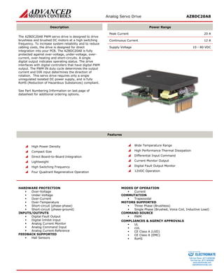
1. Analog Servo Drive AZBDC20A8
Description
Power Range
The AZBDC20A8 PWM servo drive is designed to drive brushless and brushed DC motors at a high switching frequency. To increase system reliability and to reduce cabling costs, the drive is designed for direct integration into your PCB. The AZBDC20A8 is fully protected against over-voltage, under-voltage, over- current, over-heating and short-circuits. A single digital output indicates operating status. The drive interfaces with digital controllers that have digital PWM output. The PWM IN duty cycle determines the output current and DIR input determines the direction of rotation. This servo drive requires only a single unregulated isolated DC power supply, and is fully RoHS (Reduction of Hazardous Substances) compliant.
See Part Numbering Information on last page of datasheet for additional ordering options.
Peak Current 20 A
Continuous Current 12 A
Supply Voltage 10 - 80 VDC
Features
High Power Density
Compact Size
Direct Board-to-Board Integration
Lightweight
High Switching Frequency
Four Quadrant Regenerative Operation
Wide Temperature Range
High Performance Thermal Dissipation
Differential Input Command
Current Monitor Output
Digital Fault Output Monitor
12VDC Operation
HARDWARE PROTECTION
Over-Voltage
Under-Voltage
Over-Current
Over-Temperature
Short-circuit (phase-phase)
Short-circuit (phase-ground)
INPUTS/OUTPUTS
Digital Fault Output
Digital Inhibit Input
Analog Current Monitor
Analog Command Input
Analog Current Reference
FEEDBACK SUPPORTED
Hall Sensors
MODES OF OPERATION
Current
COMMUTATION
Trapezoidal
MOTORS SUPPORTED
Three Phase (Brushless)
Single Phase (Brushed, Voice Coil, Inductive Load)
COMMAND SOURCE
PWM
COMPLIANCES & AGENCY APPROVALS
UL
cUL
CE Class A (LVD)
CE Class A (EMC)
RoHS
ELECTROMATE
Toll Free Phone (877) SERVO98
Toll Free Fax (877) SERV099
www.electromate.com
sales@electromate.com
Sold & Serviced By:
2. Analog Servo Drive AZBDC20A8
BLOCK DIAGRAM
Information on Approvals and Compliances
US and Canadian safety compliance with UL 508c, the industrial standard for power conversion electronics. UL registered under file number E140173. Note that machine components compliant with UL are considered UL registered as opposed to UL listed as would be the case for commercial products.
Compliant with European CE for both the Class A EMC Directive 2004/108/EC on Electromagnetic Compatibility (specifically EN 61000-6-4:2007 and EN 61000-6-2:2005) and LVD requirements of directive 2006/95/EC (specifically EN 60204-1:2006), a low voltage directive to protect users from electrical shock.
RoHS (Reduction of Hazardous Substances) is intended to prevent hazardous substances such as lead from being manufactured in electrical and electronic equipment.
ELECTROMATE
Toll Free Phone (877) SERVO98
Toll Free Fax (877) SERV099
www.electromate.com
sales@electromate.com
Sold & Serviced By:
3. Analog Servo Drive AZBDC20A8
SPECIFICATIONS
Power Specifications
Description
Units
Value
DC Supply Voltage Range
VDC
10 - 80
DC Bus Under Voltage Limit
VDC
9
DC Bus Over Voltage Limit
VDC
88
Maximum Peak Output Current1
A
20
Maximum Continuous Output Current
A
12
Maximum Continuous Output Power
W
912
Maximum Power Dissipation at Continuous Current
W
48
Minimum Load Inductance (Line-To-Line)2
μH
100
Low Voltage Supply Outputs
-
+6 VDC (30 mA)
Switching Frequency
kHz
31
Control Specifications
Description
Units
Value
Command Sources
-
PWM
PWM Input Frequency Range
kHz
10 - 25
Feedback Supported
-
Halls
Commutation Methods
-
Trapezoidal
Modes of Operation
-
Current
Motors Supported
-
Three Phase (Brushless), Single Phase (Brushed, Voice Coil, Inductive Load)
Hardware Protection
-
Invalid Commutation Feedback, Over Current, Over Temperature, Over Voltage, Under Voltage, Short Circuit (Phase-Phase & Phase-Ground)
Mechanical Specifications
Description
Units
Value
Agency Approvals
-
CE Class A (EMC), CE Class A (LVD), cUL, RoHS, UL
Size (H x W x D)
mm (in)
63.5 x 50.8 x 22.9 (2.5 x 2 x 0.9)
Weight
g (oz)
94.5 (3.3)
Heatsink (Base) Temperature Range3
°C (°F)
0 - 75 (32 - 167)
Storage Temperature Range
°C (°F)
-40 - 85 (-40 - 185)
P1 Connector
-
16-pin, 2.54 mm spaced header
P2 Connector
-
22-pin, 2.54 mm spaced, dual-row header
Notes
1. Maximum duration of peak current is ~2 seconds. Peak RMS value must not exceed continuous current rating of the drive.
2. Lower inductance is acceptable for bus voltages well below maximum. Use external inductance to meet requirements.
3. Additional cooling and/or heatsink may be required to achieve rated performance.
ELECTROMATE
Toll Free Phone (877) SERVO98
Toll Free Fax (877) SERV099
www.electromate.com
sales@electromate.com
Sold & Serviced By:
4. Analog Servo Drive AZBDC20A8
PIN FUNCTIONS
P1 - Signal Connector
Pin
Name
Description / Notes
I/O
1
PWM / IN
10 – 25 kHz pulse width modulated digital input command (+5V). Input duty cycle commands the output current.
I
2
SIGNAL GND
Signal Ground
GND
3
DIRECTION
Direction Input (+5 V)
I
4
CURRENT MONITOR
Current Monitor. Analog output signal proportional to the actual current output. Scaling is 6.4 A/V. Measure relative to signal ground.
O
5
INHIBIT IN
TTL level (+5 V) inhibit/enable input. Leave open to enable drive. Pull to ground to inhibit drive. Inhibit turns off all power devices.
I
6
+V HALL OUT
Low Power Supply For Hall Sensors (+6 V @ 30 mA). Referenced to signal ground. Short circuit protected.
O
7
SIGNAL GND
Signal Ground
GND
8
HALL 1
Single-ended Hall/Commutation Sensor Inputs (+5 V logic level)
I
9
HALL 2*
I
10
HALL 3
I
11
CURRENT REFERENCE
Measures the command signal to the internal current-loop. This pin has a maximum output of ±7.45 V when the drive outputs maximum peak current. Measure relative to signal ground.
O
12
FAULT OUT
TTL level (+5 V) output becomes high when power devices are disabled due to at least one of the following conditions: inhibit, invalid Hall state, output short circuit, over voltage, over temperature, power-up reset.
O
13
RESERVED
Reserved
-
14
RESERVED
-
15
RESERVED
-
16
RESERVED
-
P2 - Power Connector
Pin
Name
Description / Notes
I/O
1b
1a
HIGH VOLTAGE
DC Power Input. 3A Continuous Current Rating Per Pin.
I
2b
2a
HIGH VOLTAGE
I
3b
NC
Not Connected (Reserved)
-
3a
NC (KEY)
Key: No Connection (pin removed)
-
4b
4b
PWR GND
Power Ground (Common With Signal Ground). 3A Continuous Current Rating Per Pin.
GND
5b
5a
PWR GND
GND
6b
6a
MOTOR C
Motor Phase Outputs. Current output distributed equally across 4 pins per motor phase, 3A continuous current carrying capacity per pin.
O
7b
7a
MOTOR C
O
8b
8a
MOTOR B
O
9b
9a
MOTOR B
O
10b
10a
MOTOR A
O
11b
11a
MOTOR A
O
*For use with Single Phase (Brushed) motors, ground Hall 2 and only connect motor leads to Motor A and Motor B.
HARDWARE SETTINGS
Jumper Settings
Jumpers are SMT, 0 ohm resistors located on the underside of the drive PCB. By default, the drive is configured with the jumpers installed. Typical drive operation will not require the jumpers to be removed. Please contact the factory before jumper removal.
Jumper
Description
Configuration
SMT Jumper (0Ω Resistor)
Not Installed
Installed
JE1
Inhibit logic. Sets the logic level of inhibit pins. Labeled JE1 on the PCB of the drive.
Low Enable
Low Inhibit
JE2
Hall sensor phasing. Selects 120 or 60 degree commutation phasing. Labeled JE2 on the PCB of the drive.
60 degree
120 degree
ELECTROMATE
Toll Free Phone (877) SERVO98
Toll Free Fax (877) SERV099
www.electromate.com
sales@electromate.com
Sold & Serviced By:
5. Analog Servo Drive AZBDC20A8
MECHANICAL INFORMATION
P1 - Signal Connector
Connector Information
16-pin, 2.54 mm spaced header
Mating Connector
Details
Samtec: BCS-116-L-S-PE
Included with Drive
No
PWM / IN1SIGNAL GND2DIRECTION3CURRENT MONITOR4INHIBIT IN5+V HALL OUT6SIGNAL GND7HALL 18HALL 29HALL 310CURRENT REFERENCE11FAULT OUT12
P2 - Power Connector
Connector Information
22-pin, 2.54 mm spaced, dual-row header
Mating Connector
Details
Samtec: SSM-111-L-DV
Included with Drive
No
MOTOR A11aMOTOR A11bMOTOR A10aMOTOR A10bMOTOR B9aMOTOR B9bMOTOR B8aMOTOR B8bMOTOR C7aMOTOR C7bMOTOR C6aMOTOR C6bPWR GND5aPWR GND4aPWR GND5bNC3bPWR GND4bHIGH VOLTAGE2bHIGH VOLTAGE1bHIGH VOLTAGE1aHIGH VOLTAGE2aNC (KEY)3a
ELECTROMATE
Toll Free Phone (877) SERVO98
Toll Free Fax (877) SERV099
www.electromate.com
sales@electromate.com
Sold & Serviced By:
7. Analog Servo Drive AZBDC20A8
PART NUMBERING INFORMATION
A820- Blank:Current Mode onlyE:Encoder Velocity Mode AvailableH:Hall Velocity Mode AvailableBDCAZ Analog Drive SeriesAZDrive TypeB:Brushless/BrushedBDC:Brushless/Brushed, PWM CommandFeedback Supported6:6 Peak, 3 Continuous8:80Inverted Inhibit LogicINV: *Options available for orders with sufficient volume. Contact ADVANCED Motion Controls for more information. 10:10 Peak, 6 Continuous20:175Peak Current (Amps) 12:12 Peak, 6 ContinuousMax DC Bus Voltage (~1:10 in Volts) Additional Options* 25:25 Peak, 12.5 Continuous25:25 Peak, 12.5 Continuous40:40 Peak, 20 Continuous80V Models175V Models60:60 Peak, 30 Continuous10:10 Peak, 5 Continuous40V Models4:40
ADVANCED Motion Controls AZ series of servo drives are available in many configurations. Note that not all possible part number combinations are offered as standard drives. All models listed in the selection tables of the website are readily available, standard product offerings.
ADVANCED Motion Controls also has the capability to promptly develop and deliver specified products for OEMs with volume requests. Our Applications and Engineering Departments will work closely with your design team through all stages of development in order to provide the best servo drive solution for your system. Equipped with on-site manufacturing for quick- turn customs capabilities, ADVANCED Motion Controls utilizes our years of engineering and manufacturing expertise to decrease your costs and time-to-market while increasing system quality and reliability.
Examples of Modifications and Customized Products
Integration of Drive into Motor Housing
Integrate OEM Circuitry onto Drive PCB
Mount OEM PCB onto Drive Without Cables
Custom Control Loop Tuned to Motor Characteristics
Multi-axis Configuration for Compact System
Custom I/O Interface for System Compatibility
Custom PCB and Baseplate for Optimized Footprint
Preset Switches and Pots to Reduce User Setup
RTV/Epoxy Components for High Vibration
Optimized Switching Frequency
OEM Specified Connectors for Instant Compatibility
Ramped Velocity Command for Smooth Acceleration
OEM Specified Silkscreen for Custom Appearance
Remove Unused Features to Reduce OEM Cost
Increased Thermal Limits for High Temp. Operation
Application Specific Current and Voltage Limits
Feel free to contact Applications Engineering for further information and details.
Available Accessories
ADVANCED Motion Controls offers a variety of accessories designed to facilitate drive integration into a servo system.
Visit www.a-m-c.com to see which accessories will assist with your application design and implementation.
Power Supplies
Shunt Regulators
Mounting Card
MC1XAZ01
Filter Cards
To Motor
Drive(s)
All specifications in this document are subject to change without written notice. Actual product may differ from pictures provided in this document.
ELECTROMATE
Toll Free Phone (877) SERVO98
Toll Free Fax (877) SERV099
www.electromate.com
sales@electromate.com
Sold & Serviced By: