Advanced motion controls zbe12a8
•
0 likes•141 views

The ZBE12A8 analog servo drive can provide up to 12A of continuous current to drive brushless DC motors. It has various protection features and operating modes that can be selected with switches and pots. It interfaces with external controllers through analog voltage commands and supports feedback from hall sensors or encoders.

Recommended
More Related Content
What's hot
What's hot (20)
Viewers also liked
Viewers also liked (19)
Similar to Advanced motion controls zbe12a8
Similar to Advanced motion controls zbe12a8 (15)
More from Electromate
More from Electromate (20)
Recently uploaded
Recently uploaded (20)
Advanced motion controls zbe12a8
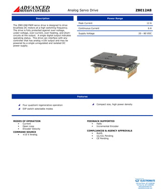
- 1. Analog Servo Drive ZBE12A8 Description Power Range Peak Current 12 A Continuous Current 6 A Supply Voltage 20 - 80 VDC The ZBE12A8 PWM servo drive is designed to drive brushless DC motors at a high switching frequency. The drive is fully protected against over-voltage, under-voltage, over-current, over-heating, and short-circuits at the output. A single digital output indicates operating status. This drive can interface with any controller that has analog ±10V output and may be powered by a single unregulated and isolated DC power supply. Features Four quadrant regenerative operation DIP switch selectable modes Compact size, high power density MODES OF OPERATION ƒ Current ƒ Open Loop ƒ Encoder Velocity COMMAND SOURCE ƒ ±10 V Analog FEEDBACK SUPPORTED ƒ Halls ƒ Incremental Encoder COMPLIANCES & AGENCY APPROVALS ƒ RoHS ƒ UL/cUL Pending ƒ CE Pending Sold & Serviced By: ELECTROMATE Toll Free Phone (877) SERVO98 Toll Free Fax (877) SERV099 www.electromate.com sales@electromate.com
- 2. Analog Servo Drive ZBE12A8 BLOCK DIAGRAM P1-14 P1-16 60/120 INHSEL ALL UNLABELLED HIGHS SHARE AN INTERNAL +5V CURR/VEL CURR/VEL 10K 20K 20K J2 J1 - + - + 40K 40K 500K - 500K + 500K 15K SW3 CURRENT SENSE 10K - + SW2 SW4 SW1 10K ALL GROUNDS ARE INTERNALLY CONNECTED INTERNAL POWER-SUPPLY FOR HALL SENSORS +VHall 15K POT1 10K 50K 24K 20K 0.01 P2-6 POWER GND P2-2,3 MOTOR C P2-7,8 CURRENT REFERENCE FAULT P1-5 INHIBIT 10K 10K HIGH VOLTAGE P2-4,5 5K P1-1 -REF IN 0.1 FUNCTIONAL BLOCK DIAGRAM P1-4 ZBE6A6 / ZBE12A8 OFFSET P1-3 +REF IN 10K CURRENT FEEDBACK H1 H3 HALL SENSORS P1-8,9,10 RESERVED P2-1 CURRENT MONITOR P1-13 H2 P2-9,10 LOGIC MOSFET CONTROL MOTOR B P2-11,12 DRIVE MOTOR A P1-2 P1-11 F/V CONVERTER HALL 1, 2, 3 VELOCITY DIRECTION P1-12 PWM FEEDBACK 5K P1-7 P1-6 P1-15 VELOCITY MONITOR CW 10K MODE SELECTION TABLE SW1 SW2 SW3 CURRENT OPEN-LOOP ENCODER VELOCITY OFF ON ON ON OFF OFF OFF ON OFF NOTES: - RECOMMENDED SETTING FOR CURRENT MODE: POT 1 FULLY CCW. - AMPLIFIERS ARE SHIPPED IN CURRENT MODE WITH MAXIMUM CURRENT SETTINGS. ENCODER-B ENCODER-A N/C Approvals and Compliances US and Canadian safety compliance with UL 508c, the industrial standard for power conversion electronics. UL registered under file number E140173. Note that machine components compliant with UL are considered UL registered as opposed to UL listed as would be the case for commercial products. Compliant with European CE for both the Class A EMC Directive 89/336/EEC on Electromagnetic Compatibility (specifically EN 61000-6-4:2001, EN 61000-6-2:2001, EN 61000-3-2:2000, and EN 61000-3-3:1995/A1:2001) and LVD requirements of directive 73/23/EEC (specifically EN 60204-1), a low voltage directive to protect users from electrical shock. RoHS (Reduction of Hazardous Substances) is intended to prevent hazardous substances such as lead from being manufactured in electrical and electronic equipment. Sold & Serviced By: ELECTROMATE Toll Free Phone (877) SERVO98 Toll Free Fax (877) SERV099 www.electromate.com sales@electromate.com
- 3. Analog Servo Drive ZBE12A8 SPECIFICATIONS Power Stage Specifications Description Units Value DC Supply Voltage VDC 20 - 80 Over Voltage Limit VDC 86 Peak Output Current1 A 12 Maximum Continuous Output Current A 6 Maximum Power Dissipation at Continuous Current W 24 Minimum Load Inductance (Line-To-Line)2 μH 100 Switching Frequency kHz 32 Control Specifications Description Units Value Command Sources - ±10 V Analog Feedback Supported - Halls, Incremental Encoder Commutation Methods - External, Trapezoidal Modes of Operation - Current, Encoder Velocity, Open Loop Hardware Protection - Over Current, Over Temperature, Over Voltage, Short Circuit (Phase- Phase & Phase-Ground) Current Loop Sample Time μs 31.3 Mechanical Specifications Description Units Value Size (H x W x L) mm (in) 27.7 x 50.8 x 68.6 (1.1 x 2 x 2.7) Heatsink (Base) Temperature Range3 °C (°F) 0 - 65 (32 - 149) P1 Connector - 16-pin, 2.54 mm spaced header P2 Connector - 12-pin, 2.54 mm spaced header Notes 1. Maximum duration of peak current is ~2 seconds. 2. Low inductance motors, such as ‘pancake’ and ‘basket-wound’, require external inductors. The Minimum Load Inductance provided assumes the highest allowed bus voltage. Lower inductances are acceptable for lower bus voltages. 3. Additional cooling and/or heatsink may be required to achieve rated performance. Sold & Serviced By: ELECTROMATE Toll Free Phone (877) SERVO98 Toll Free Fax (877) SERV099 www.electromate.com sales@electromate.com
- 4. Analog Servo Drive ZBE12A8 PIN FUNCTIONS P1 - Signal Connector Pin Name Description / Notes I/O 1 +REF IN Differential Reference Input (±10 V Operating Range, ±15 V Maximum Input) I 2 SIGNAL GND Signal Ground SGND 3 -REF IN Differential Reference Input (±10 V Operating Range, ±15 V Maximum Input) I 4 OFFSET Connection to external resistance for command offset adjustments. - 5 INHIBIT IN TTL level (+5 V) inhibit/enable input. Leave open to enable drive. Pull to ground to inhibit drive. Inhibit turns off all power devices. I 6 +V HALL OUT Low Power Supply For Hall Sensors (+6 V @ 30 mA). Referenced to signal ground. Short circuit protected. O 7 SIGNAL GND Signal Ground SGND 8 HALL 1 I 9 HALL 2 Single-ended Hall/Commutation Sensor Inputs (+5 V logic level) I 10 HALL 3 I 11 ENCODER-B IN Single-ended encoder channel B input. +5 V logic level. I 12 ENCODER-A IN Single-ended encoder channel A input. +5 V logic level. I 13 CURRENT MONITOR Current Monitor. Analog output signal proportional to the actual current output. Scaling is 3.92 A/V by default but may be set to half this value if the drive has a Current Scaling switch. Measure relative to signal ground. O 14 CURRENT REFERENCE Measures the command signal to the internal current-loop. This pin has a maximum output of ±TBA when the drive outputs maximum peak current. O 15 VELOCITY MONITOR When used in current or encoder velocity mode, voltage is proportional to the speed of the motor. In open-loop mode, voltage is proportional to the PWM duty cycle. Encoder F/V scaling: TBA O 16 FAULT OUT TTL level (+5 V) output becomes high when power devices are disabled due to at least one of the following conditions: inhibit, invalid Hall state, output short circuit, over voltage, over temperature, power-up reset. O P2 - Power Connector Pin Name Description / Notes I/O 1 RESERVED Reserved - 2 PWR GND Power Ground (Common With Signal Ground). 3A Continuous Current Rating Per Pin. PGND 3 PWR GND Power Ground (Common With Signal Ground). 3A Continuous Current Rating Per Pin. PGND 4 HIGH VOLTAGE DC Power Input. 3A Continuous Current Rating Per Pin. I 5 HIGH VOLTAGE DC Power Input. 3A Continuous Current Rating Per Pin. I 6 RESERVED Reserved - 7 MOTOR C Motor Phase C. 3A Continuous Current Rating Per Pin. O 8 MOTOR C Motor Phase C. 3A Continuous Current Rating Per Pin. O 9 MOTOR B Motor Phase B. 3A Continuous Current Rating Per Pin. O 10 MOTOR B Motor Phase B. 3A Continuous Current Rating Per Pin. O 11 MOTOR A Motor Phase A. 3A Continuous Current Rating Per Pin. O 12 MOTOR A Motor Phase A. 3A Continuous Current Rating Per Pin. O Sold & Serviced By: ELECTROMATE Toll Free Phone (877) SERVO98 Toll Free Fax (877) SERV099 www.electromate.com sales@electromate.com
- 5. Analog Servo Drive ZBE12A8 HARDWARE SETTINGS Switch Functions Setting Switch Description On Off 1 Open-loop mode selector. Activates internal PWM feedback. Open-loop mode Other modes 2 Activate velocity feedback or monitor. For encoder velocity mode, activates feedback. For current mode, activates velocity monitor. Active Inactive 3 Current mode selector. Current mode Other modes 4 Velocity feedback polarity. Standard Inverted Potentiometer Functions Potentiometer Description Turning CCW 1 Loop gain adjustment for voltage/velocity modes. Turn this pot fully ccw in current mode. Increases gain Sold & Serviced By: ELECTROMATE Toll Free Phone (877) SERVO98 Toll Free Fax (877) SERV099 www.electromate.com sales@electromate.com
- 6. Analog Servo Drive ZBE12A8 MECHANICAL INFORMATION P1 - Signal Connector Connector Information 16-pin, 2.54 mm spaced header Mating Connector Samtec: BCS-116-L-S-PE 15 VELOCITY MONITOR 13 CURRENT MONITOR 11 ENCODER-B IN 9 HALL 2 7 SIGNAL GND 5 INHIBIT IN 3 -REF IN 1 +REF IN 2 SIGNAL GND 4 OFFSET 6 +V HALL OUT 8 HALL 1 10 HALL 3 12 ENCODER-A IN 14 CURRENT REFERENCE 16 FAULT OUT P2 - Power Connector Connector Information 12-pin, 2.54 mm spaced header Mating Connector Samtec: BCS-112-L-S-PE 11 MOTOR A 9 MOTOR B 7 MOTOR C 5 HIGH VOLTAGE 3 PWR GND 2 PWR GND 4 HIGH VOLTAGE 8 MOTOR C 10 MOTOR B 12 MOTOR A Sold & Serviced By: ELECTROMATE Toll Free Phone (877) SERVO98 Toll Free Fax (877) SERV099 www.electromate.com sales@electromate.com
- 7. Analog Servo Drive ZBE12A8 MOUNTING DIMENSIONS Sold & Serviced By: ELECTROMATE Toll Free Phone (877) SERVO98 Toll Free Fax (877) SERV099 www.electromate.com sales@electromate.com
- 8. Analog Servo Drive ZBE12A8 PART NUMBERING INFORMATION ZBE 12 A 8 - Basic Drive Features ANP: Analog positioning. H: QD: Quick disconnect on power port. INV: Inverted inhibit logic. Combinations: HQD: H + QD. HQDI: H + QD + INV. QDI: QD + INV. Revision Peak Current Peak Voltage Additional Options Each character has a specific meaning as given below. Note that some brushed drives do not use this placeholder. : Brushed drive. B: Brushless drive. C: Closed current loop. Only applies to brushless PWM input drives. D: Brushless PWM (digital) input drive E: Encoder feedback support. Only applies to lower power drives. S: S-Series drive. X: Brushless drive with unique features. Z: Z-Series brushed/brushless drive. Maximum peak current rating in Amps. Peak voltage rating scaled 1:10 in Volts. Hall velocity mode. Options not listed above are only for custom products. Contact manufacturer for information on custom products. Assigned a letter (A through Z) by manufacturer. Additional Drive Feature AC: AC power input. FAC: Front mounted AC power input. DD: PWM (digital) input drive. Only applies to brushed drives. DDC: PWM (digital) input drive with closed current loop. Only applies to brushed drives. I: Optical isolation between power devices and general I/O. DigiFlex®Performance™ series of products are available in many configurations. All models listed on the website are readily available, standard product offerings. Other combinations or possibilities can be made available for OEMs with volume requests of 100 or more. Contact Applications Engineering for further information and details. Sold & Serviced By: ELECTROMATE Toll Free Phone (877) SERVO98 Toll Free Fax (877) SERV099 www.electromate.com sales@electromate.com All specifications in this document are subject to change without written notice. Actual product may differ from pictures provided in this document.