Accelerate your Kubernetes clusters with Varnish CachingThijs Feryn
A presentation about the usage and availability of Varnish on Kubernetes. This talk explores the capabilities of Varnish caching and shows how to use the Varnish Helm chart to deploy it to Kubernetes.
This presentation was delivered at K8SUG Singapore. See https://feryn.eu/presentations/accelerate-your-kubernetes-clusters-with-varnish-caching-k8sug-singapore-28-2024 for more details.
Smart TV Buyer Insights Survey 2024 by 91mobiles.pdf91mobiles
91mobiles recently conducted a Smart TV Buyer Insights Survey in which we asked over 3,000 respondents about the TV they own, aspects they look at on a new TV, and their TV buying preferences.
DevOps and Testing slides at DASA ConnectKari Kakkonen
My and Rik Marselis slides at 30.5.2024 DASA Connect conference. We discuss about what is testing, then what is agile testing and finally what is Testing in DevOps. Finally we had lovely workshop with the participants trying to find out different ways to think about quality and testing in different parts of the DevOps infinity loop.
Connector Corner: Automate dynamic content and events by pushing a buttonDianaGray10
Here is something new! In our next Connector Corner webinar, we will demonstrate how you can use a single workflow to:
Create a campaign using Mailchimp with merge tags/fields
Send an interactive Slack channel message (using buttons)
Have the message received by managers and peers along with a test email for review
But there’s more:
In a second workflow supporting the same use case, you’ll see:
Your campaign sent to target colleagues for approval
If the “Approve” button is clicked, a Jira/Zendesk ticket is created for the marketing design team
But—if the “Reject” button is pushed, colleagues will be alerted via Slack message
Join us to learn more about this new, human-in-the-loop capability, brought to you by Integration Service connectors.
And...
Speakers:
Akshay Agnihotri, Product Manager
Charlie Greenberg, Host
Essentials of Automations: Optimizing FME Workflows with ParametersSafe Software
Are you looking to streamline your workflows and boost your projects’ efficiency? Do you find yourself searching for ways to add flexibility and control over your FME workflows? If so, you’re in the right place.
Join us for an insightful dive into the world of FME parameters, a critical element in optimizing workflow efficiency. This webinar marks the beginning of our three-part “Essentials of Automation” series. This first webinar is designed to equip you with the knowledge and skills to utilize parameters effectively: enhancing the flexibility, maintainability, and user control of your FME projects.
Here’s what you’ll gain:
- Essentials of FME Parameters: Understand the pivotal role of parameters, including Reader/Writer, Transformer, User, and FME Flow categories. Discover how they are the key to unlocking automation and optimization within your workflows.
- Practical Applications in FME Form: Delve into key user parameter types including choice, connections, and file URLs. Allow users to control how a workflow runs, making your workflows more reusable. Learn to import values and deliver the best user experience for your workflows while enhancing accuracy.
- Optimization Strategies in FME Flow: Explore the creation and strategic deployment of parameters in FME Flow, including the use of deployment and geometry parameters, to maximize workflow efficiency.
- Pro Tips for Success: Gain insights on parameterizing connections and leveraging new features like Conditional Visibility for clarity and simplicity.
We’ll wrap up with a glimpse into future webinars, followed by a Q&A session to address your specific questions surrounding this topic.
Don’t miss this opportunity to elevate your FME expertise and drive your projects to new heights of efficiency.
Transcript: Selling digital books in 2024: Insights from industry leaders - T...BookNet Canada
The publishing industry has been selling digital audiobooks and ebooks for over a decade and has found its groove. What’s changed? What has stayed the same? Where do we go from here? Join a group of leading sales peers from across the industry for a conversation about the lessons learned since the popularization of digital books, best practices, digital book supply chain management, and more.
Link to video recording: https://bnctechforum.ca/sessions/selling-digital-books-in-2024-insights-from-industry-leaders/
Presented by BookNet Canada on May 28, 2024, with support from the Department of Canadian Heritage.
Builder.ai Founder Sachin Dev Duggal's Strategic Approach to Create an Innova...Ramesh Iyer
In today's fast-changing business world, Companies that adapt and embrace new ideas often need help to keep up with the competition. However, fostering a culture of innovation takes much work. It takes vision, leadership and willingness to take risks in the right proportion. Sachin Dev Duggal, co-founder of Builder.ai, has perfected the art of this balance, creating a company culture where creativity and growth are nurtured at each stage.
Key Trends Shaping the Future of Infrastructure.pdfCheryl Hung
Keynote at DIGIT West Expo, Glasgow on 29 May 2024.
Cheryl Hung, ochery.com
Sr Director, Infrastructure Ecosystem, Arm.
The key trends across hardware, cloud and open-source; exploring how these areas are likely to mature and develop over the short and long-term, and then considering how organisations can position themselves to adapt and thrive.
GDG Cloud Southlake #33: Boule & Rebala: Effective AppSec in SDLC using Deplo...James Anderson
Effective Application Security in Software Delivery lifecycle using Deployment Firewall and DBOM
The modern software delivery process (or the CI/CD process) includes many tools, distributed teams, open-source code, and cloud platforms. Constant focus on speed to release software to market, along with the traditional slow and manual security checks has caused gaps in continuous security as an important piece in the software supply chain. Today organizations feel more susceptible to external and internal cyber threats due to the vast attack surface in their applications supply chain and the lack of end-to-end governance and risk management.
The software team must secure its software delivery process to avoid vulnerability and security breaches. This needs to be achieved with existing tool chains and without extensive rework of the delivery processes. This talk will present strategies and techniques for providing visibility into the true risk of the existing vulnerabilities, preventing the introduction of security issues in the software, resolving vulnerabilities in production environments quickly, and capturing the deployment bill of materials (DBOM).
Speakers:
Bob Boule
Robert Boule is a technology enthusiast with PASSION for technology and making things work along with a knack for helping others understand how things work. He comes with around 20 years of solution engineering experience in application security, software continuous delivery, and SaaS platforms. He is known for his dynamic presentations in CI/CD and application security integrated in software delivery lifecycle.
Gopinath Rebala
Gopinath Rebala is the CTO of OpsMx, where he has overall responsibility for the machine learning and data processing architectures for Secure Software Delivery. Gopi also has a strong connection with our customers, leading design and architecture for strategic implementations. Gopi is a frequent speaker and well-known leader in continuous delivery and integrating security into software delivery.
GDG Cloud Southlake #33: Boule & Rebala: Effective AppSec in SDLC using Deplo...
Advanced motion controls sx30a8
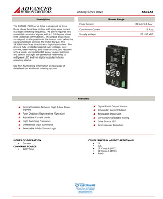
1. Analog Servo Drive SX30A8
Description
Power Range
The SX30A8 PWM servo drive is designed to drive three phase brushless motors with sine wave current at a high switching frequency. The drive requires two sinusoidal command signals with a 120-degree phase shift (external commutation). The phase angle must correspond to the position of the motor rotor, while the signal amplitude controls the motor torque. The SX30A8 interfaces directly with digital controllers. The drive is fully protected against over-voltage, over- current, over-heating, and short-circuits, and requires only a single unregulated DC power supply (all logic and control voltages are generated internally). A red/green LED and two digital outputs indicate operating status.
See Part Numbering Information on last page of datasheet for additional ordering options.
Peak Current 30 A (21.2 ARMS)
Continuous Current 15 ARMS
Supply Voltage 20 - 80 VDC
Features
Optical Isolation Between High & Low Power Signals
Four Quadrant Regenerative Operation
Adjustable Current Limits
High Switching Frequency
Differential Input Command
Selectable Inhibit/Enable Logic
Digital Fault Output Monitor
Sinusoidal Current Output
Adjustable Input Gain
DIP Switch Selectable Tuning
Drive Status LED
No Crossover Distortion
MODES OF OPERATION
Current
COMMAND SOURCE
120° Sine
COMPLIANCES & AGENCY APPROVALS
UL
cUL
CE Class A (LVD)
CE Class A (EMC)
RoHS
ELECTROMATE
Toll Free Phone (877) SERVO98
Toll Free Fax (877) SERV099
www.electromate.com
sales@electromate.com
Sold & Serviced By:
2. Analog Servo Drive SX30A8
BLOCK DIAGRAM
Information on Approvals and Compliances
US and Canadian safety compliance with UL 508c, the industrial standard for power conversion electronics. UL registered under file number E140173. Note that machine components compliant with UL are considered UL registered as opposed to UL listed as would be the case for commercial products.
Compliant with European CE for both the Class A EMC Directive 2004/108/EC on Electromagnetic Compatibility (specifically EN 61000-6-4:2007 and EN 61000-6-2:2005) and LVD requirements of directive 2006/95/EC (specifically EN 60204-1:2006), a low voltage directive to protect users from electrical shock.
RoHS (Reduction of Hazardous Substances) is intended to prevent hazardous substances such as lead from being manufactured in electrical and electronic equipment.
ELECTROMATE
Toll Free Phone (877) SERVO98
Toll Free Fax (877) SERV099
www.electromate.com
sales@electromate.com
Sold & Serviced By:
3. Analog Servo Drive SX30A8
SPECIFICATIONS
Power Specifications
Description
Units
Value
DC Supply Voltage Range
VDC
20 - 80
DC Bus Over Voltage Limit
VDC
86
Maximum Peak Output Current1
A
30
Maximum Continuous Sine Wave Current
Arms
15
Maximum Continuous Output Power
W
1140
Maximum Power Dissipation at Continuous Current
W
60
Minimum Load Inductance (Line-To-Line)2
μH
200
Switching Frequency
kHz
27
Control Specifications
Description
Units
Value
Command Sources
-
120° Sine
Commutation Methods
-
Sinusoidal
Modes of Operation
-
Current
Motors Supported
-
Three Phase (Brushless)
Hardware Protection
-
Over Current, Over Temperature, Over Voltage, Short Circuit (Phase-Phase & Phase-Ground)
Primary I/O Logic Level
-
5V TTL
Mechanical Specifications
Description
Units
Value
Agency Approvals
-
CE Class A (EMC), CE Class A (LVD), cUL, RoHS, UL
Size (H x W x D)
mm (in)
186.7 x 111.8 x 36.8 (7.4 x 4.4 x 1.4)
Weight
g (oz)
680 (24)
Heatsink (Base) Temperature Range3
°C (°F)
0 - 65 (32 - 149)
Storage Temperature Range
°C (°F)
-40 - 85 (-40 - 185)
Form Factor
-
Panel Mount
P1 Connector
-
15-pin, female D-sub
P2 Connector
-
5-port, 5.08 mm spaced, screw terminal
Notes
1. Maximum duration of peak current is ~2 seconds.
2. Lower inductance is acceptable for bus voltages well below maximum. Use external inductance to meet requirements.
3. Additional cooling and/or heatsink may be required to achieve rated performance.
ELECTROMATE
Toll Free Phone (877) SERVO98
Toll Free Fax (877) SERV099
www.electromate.com
sales@electromate.com
Sold & Serviced By:
4. Analog Servo Drive SX30A8
PIN FUNCTIONS
P1 - Signal Connector
Pin
Name
Description / Notes
I/O
1
SIGNAL GND
Signal Ground
SGND
2
+REF-IN-A
Differential reference input, maximum ±10 V, 40K input resistance
I
3
-REF-IN-A
I
4
SIGNAL GND
Signal Ground
SGND
5
+REF-IN-B
Differential reference input, maximum ±10 V, 40K input resistance
I
6
-REF-IN-B
I
7
FAULT OUT
TTL level (+5 V) output becomes high when power devices are disabled due to at least one of the following conditions: inhibit, output short circuit, over voltage, over temperature, power-up reset.
O
8
INHIBIT/ENABLE IN
TTL level (+5 V) inhibit/enable input. Pull to ground to enable drive (SW10-OFF). Pull to ground to inhibit drive (SW10-ON). Inhibit turns off all power devices.
I
9
CURRENT MONITOR A OUT
Phase Current Monitor. 7.25 V = amplifier peak rated current .
O
10
CURRENT MONITOR B OUT
O
11
CURRENT MONITOR C OUT
O
12
SIGNAL GND
Signal Ground
SGND
13
RMS CURRENT LIMIT
The RMS current limit can be controlled by an external voltage; 5 V = maximum RMS current limit. This is referenced to Signal Ground. No input to this pin is necessary to obtain maximum current.
I
14
OVER-CURRENT FAULT OUT
This transistor output becomes high if RMS current (in any phase) exceeds RMS current limit. This creates a fault condition. Drive will re-enable when the RMS current returns to values within the RMS current limit range.
O
15
NC
Not Connected (Reserved)
-
P2 - Power Connector
Pin
Name
Description / Notes
I/O
1
MOTOR A
Motor Phase A
O
2
MOTOR B
Motor Phase B
O
3
MOTOR C
Motor Phase C
O
4
PWR GND
Power Ground (Isolated From Signal Ground)
PGND
5
HIGH VOLTAGE
DC Power Input
I
ELECTROMATE
Toll Free Phone (877) SERVO98
Toll Free Fax (877) SERV099
www.electromate.com
sales@electromate.com
Sold & Serviced By:
5. Analog Servo Drive SX30A8
HARDWARE SETTINGS
Switch Functions
Switch
Description
Setting
On
Off
1
Input range selection. Input range can be set to ±5 V or ±10 V. Must be set the same as switch 2.
±5 V
±10 V
2
Input range selection. Input range can be set to ±5 V or ±10 V. Must be set the same as switch 1.
±5 V
±10 V
3
Peak Current Limit. Sets the peak current limit to 50% or 100% of the maximum peak current. Must be set the same as switch 4.
100%
50%
4
Peak Current Limit. Sets the peak current limit to 50% or 100% of the maximum peak current. Must be set the same as switch 3.
100%
50%
5
Reserved Function
-
-
6
Bit 0 of binary value for RMS current limit setting. See details below.
1
0
7
Bit 1 of binary value for RMS current limit setting. See details below.
1
0
8
Current loop proportional gain adjustment. ON by default.
Decrease
Increase
9
Current loop integral gain. Activates or deactivates integration. OFF by default.
Inactive
Active
10
Inhibit logic. Sets the logic level of inhibit pins.
Active Low
Active High
Additional Details
Switches 1 & 2, and switches 3 & 4 must be set the same. Switches 6 and 7 can be used to reduce the continuous current limit to a percentage given in the table below. 100% means no reduction.
% Of Maximum Continuous Current Limit
Switch 6
Switch 7
25
OFF
OFF
50
ON
OFF
100
OFF
ON
ON
ON
Through-hole Components†
Location
Description
CF1*
Current Loop Integrator. Three identical through-hole capacitors that can be added for more precise current loop tuning. See section below on Tuning with Through-hole components for more details.
CF2*
RF1*
Current Loop Proportional Gain. Three identical through-hole resistors that can be added for more precise current loop tuning. See section below on Tuning with Through-hole components for more details.
RF2*
Tuning With Through-hole Components
In general, the drive will not need to be further tuned with through-hole components. However, for applications requiring more precise tuning than what is offered by the potentiometers and dipswitches, the drive can be manually modified with through-hole resistors and capacitors as denoted in the above table. By default, the through-hole locations are not populated when the drive is shipped. Before attempting to add through-hole components to the board, consult the section on loop tuning in the installation notes on the manufacturer’s website. Some general rules of thumb to follow when adding through-hole components are:
• A larger resistor value will increase the proportional gain, and therefore create a faster response time.
• A larger capacitor value will increase the integration time, and therefore create a slower response time.
Proper tuning using the through-hole components will require careful observation of the loop response on a digital oscilloscope to find the optimal through-hole component values for the specific application.
†Note: Damage done to the drive while performing these modifications will void the warranty.
ELECTROMATE
Toll Free Phone (877) SERVO98
Toll Free Fax (877) SERV099
www.electromate.com
sales@electromate.com
Sold & Serviced By:
6. Analog Servo Drive SX30A8
MECHANICAL INFORMATION
P1 - Signal Connector
Connector Information
15-pin, female D-sub
Mating Connector
Details
TYCO: Plug P/N 205206-3; Housing P/N 5745172-1; Terminals P/N 1658540-5 (loose) or 1658540-4 (strip)
Included with Drive
No
CURRENT MONITOR A OUT9CURRENT MONITOR B OUT10CURRENT MONITOR C OUT11RMS CURRENT LIMIT13SIGNAL GND12OVER-CURRENT FALUT OUT14NC15INHIBIT/ENABLE IN8FAULT OUT7-REF-IN-B6+REF-IN-B5SIGNAL GND4-REF-IN-A3+REF-IN-A2SIGNAL GND1
P2 - Power Connector
Connector Information
5-port, 5.08 mm spaced, screw terminal
Mating Connector
Details
Not applicable
Included with Drive
Not applicable
MOTOR A1MOTOR B2MOTOR C3PWR GND4HIGH VOLTAGE5
ELECTROMATE
Toll Free Phone (877) SERVO98
Toll Free Fax (877) SERV099
www.electromate.com
sales@electromate.com
Sold & Serviced By:
8. Analog Servo Drive SX30A8
PART NUMBERING INFORMATION
ADVANCED Motion Controls analog series of servo drives are available in many configurations. Note that not all possible part number combinations are offered as standard drives. All models listed in the selection tables of the website are readily available, standard product offerings.
ADVANCED Motion Controls also has the capability to promptly develop and deliver specified products for OEMs with volume requests. Our Applications and Engineering Departments will work closely with your design team through all stages of development in order to provide the best servo drive solution for your system. Equipped with on-site manufacturing for quick- turn customs capabilities, ADVANCED Motion Controls utilizes our years of engineering and manufacturing expertise to decrease your costs and time-to-market while increasing system quality and reliability.
Examples of Modifications and Customized Products
Integration of Drive into Motor Housing
Integrate OEM Circuitry onto Drive PCB
Mount OEM PCB onto Drive Without Cables
Custom Control Loop Tuned to Motor Characteristics
Multi-axis Configuration for Compact System
Custom I/O Interface for System Compatibility
Custom PCB and Baseplate for Optimized Footprint
Preset Switches and Pots to Reduce User Setup
RTV/Epoxy Components for High Vibration
Optimized Switching Frequency
OEM Specified Connectors for Instant Compatibility
Ramped Velocity Command for Smooth Acceleration
OEM Specified Silkscreen for Custom Appearance
Remove Unused Features to Reduce OEM Cost
Increased Thermal Limits for High Temp. Operation
Application Specific Current and Voltage Limits
Feel free to contact Applications Engineering for further information and details.
Available Accessories
ADVANCED Motion Controls offers a variety of accessories designed to facilitate drive integration into a servo system.
Visit www.a-m-c.com to see which accessories will assist with your application design and implementation. Power Supplies
Shunt Regulators
Drive(s)
Filter Cards
To Motor
All specifications in this document are subject to change without written notice. Actual product may differ from pictures provided in this document.
A8- B or BX:Brushless drive. Maximum peak current rating in Amps. Peak voltage rating scaled 1:10 in Volts.:DC Power SupplyBE:Encoder Velocity Mode AvailableBD:PWM CommandBDC:PWM Command, Closed Current LoopS or SX:Commutated Sine CommandAssigned a letter (A through Z) by manufacturer. AC:AC Power SupplyFAC:AC Power Connecter Relocated to the FrontI:Optical IsolationIsolation Option** 30SX-QD:Quick Disconnect* Options available for orders with sufficient volume. Contact ADVANCED Motion Controls for more information. ** Isolation comes standard on all AC supply drives and most DC supply drives 200V and above. Consult selection tables of the website or drive datasheet block diagram to see if isolation is included. Additional Options*Drive TypePeak CurrentPeak VoltageRevisionPower Supply
ELECTROMATE
Toll Free Phone (877) SERVO98
Toll Free Fax (877) SERV099
www.electromate.com
sales@electromate.com
Sold & Serviced By: