Download to read offline
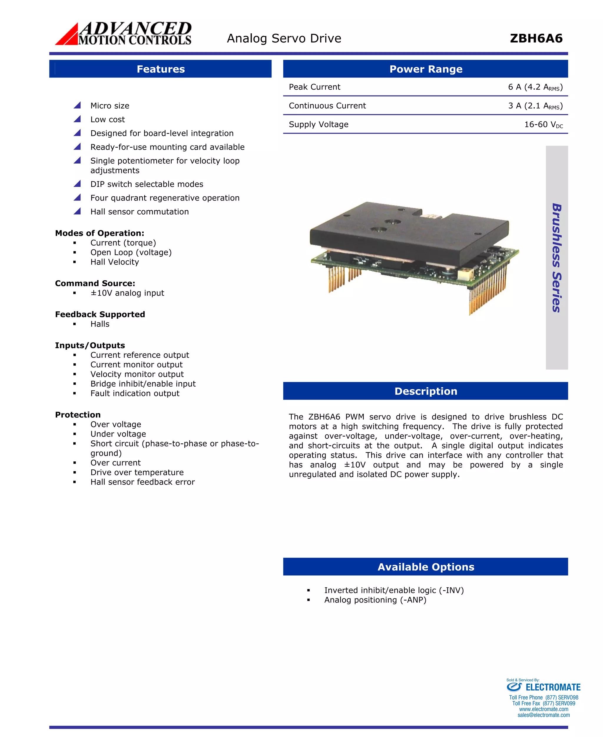
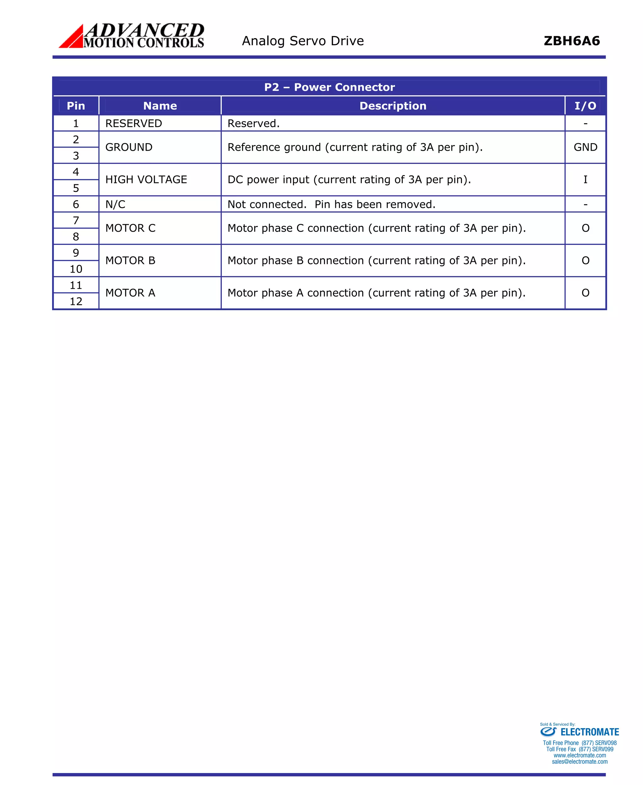

The ZBH6A6 analog servo drive is designed to drive brushless DC motors with a peak current of 6A. It has hall sensor commutation and accepts a ±10V analog input signal. It provides status outputs for current, velocity, and faults.


![Coded Agents – with UiPath SDK + LangGraph [Virtual Hands-on Workshop]](https://cdn.slidesharecdn.com/ss_thumbnails/codedagentsdeck-251215155422-5497c599-thumbnail.jpg?width=640&height=640&fit=bounds)


