Download to read offline
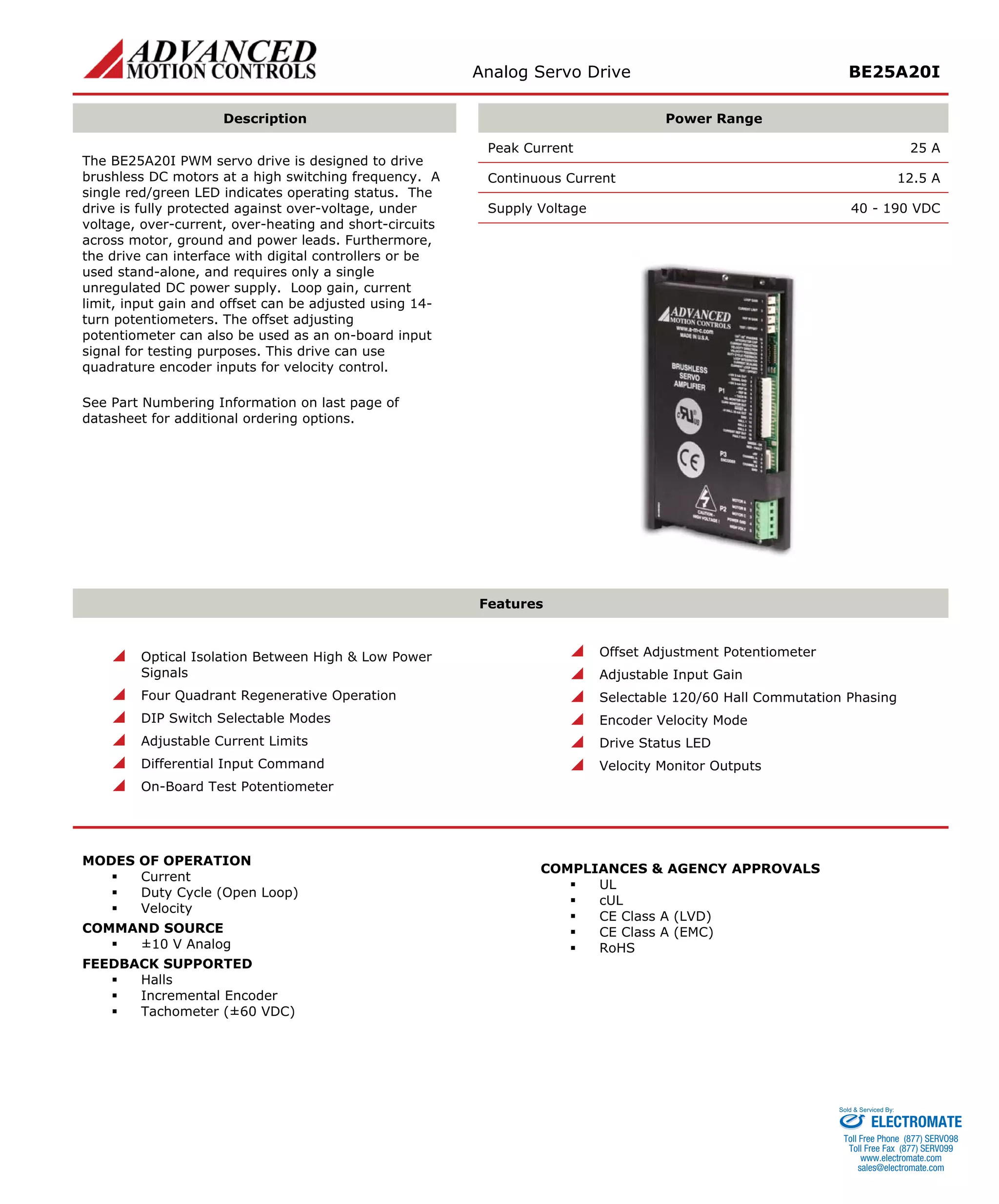
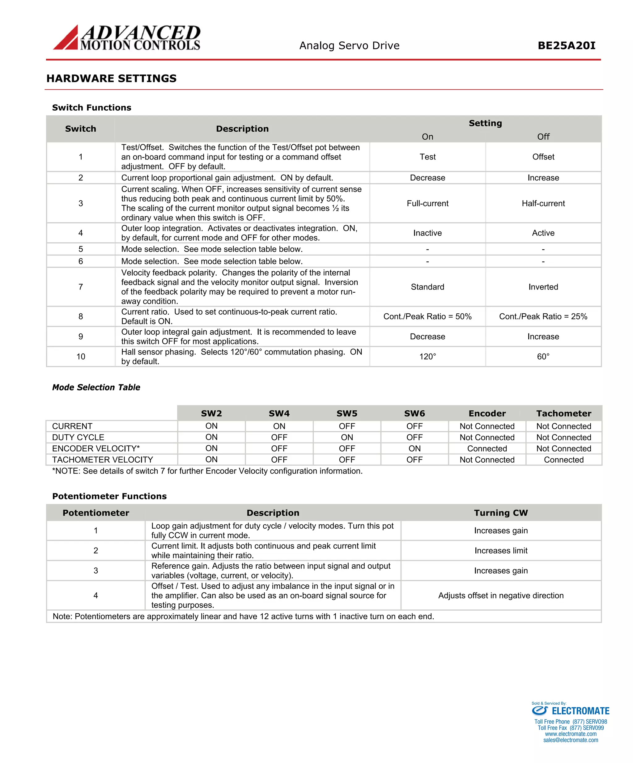
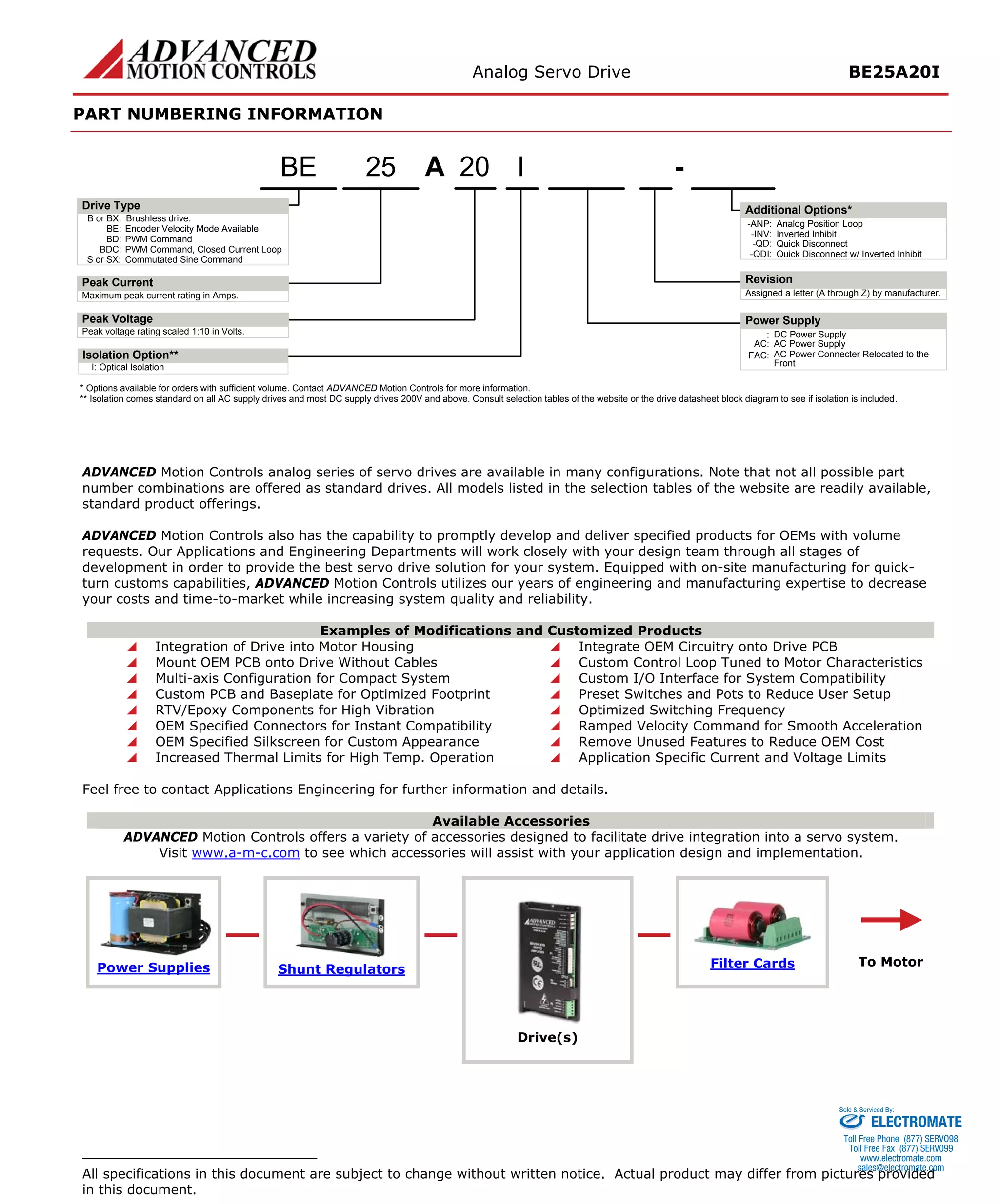

The document describes an analog servo drive called the BE25A20I. It has the following key specifications: - It can provide up to 25A of peak current and 12.5A of continuous current. - It is designed to drive brushless DC motors and can operate in various modes like current, duty cycle, and velocity modes. - It has protections against overheating, overvoltage, undervoltage, and short circuits. - It can interface with encoders, Hall sensors, or tachometers for motor feedback and supports motors with three phases.


![Vibe Coding vs. Spec-Driven Development [Free Meetup]](https://cdn.slidesharecdn.com/ss_thumbnails/vibecodingvsspecdrivendevelopment-251209105622-43f455e7-thumbnail.jpg?width=640&height=640&fit=bounds)


