Download to read offline
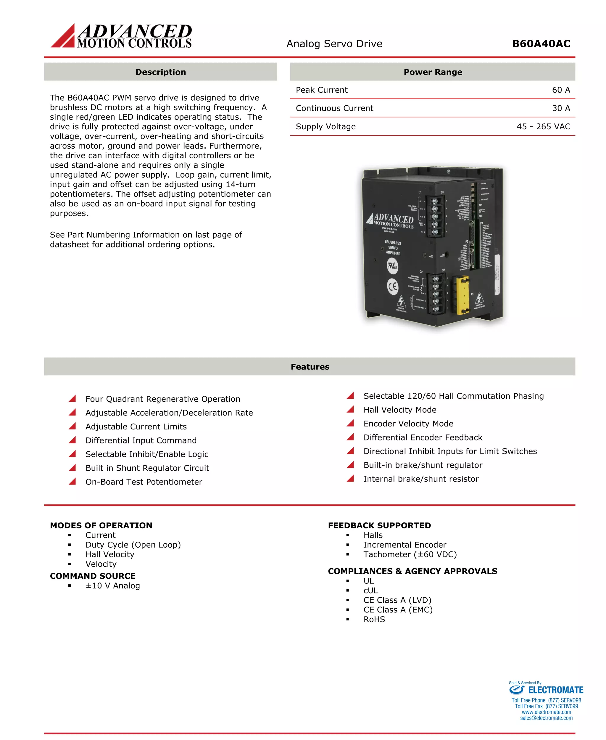
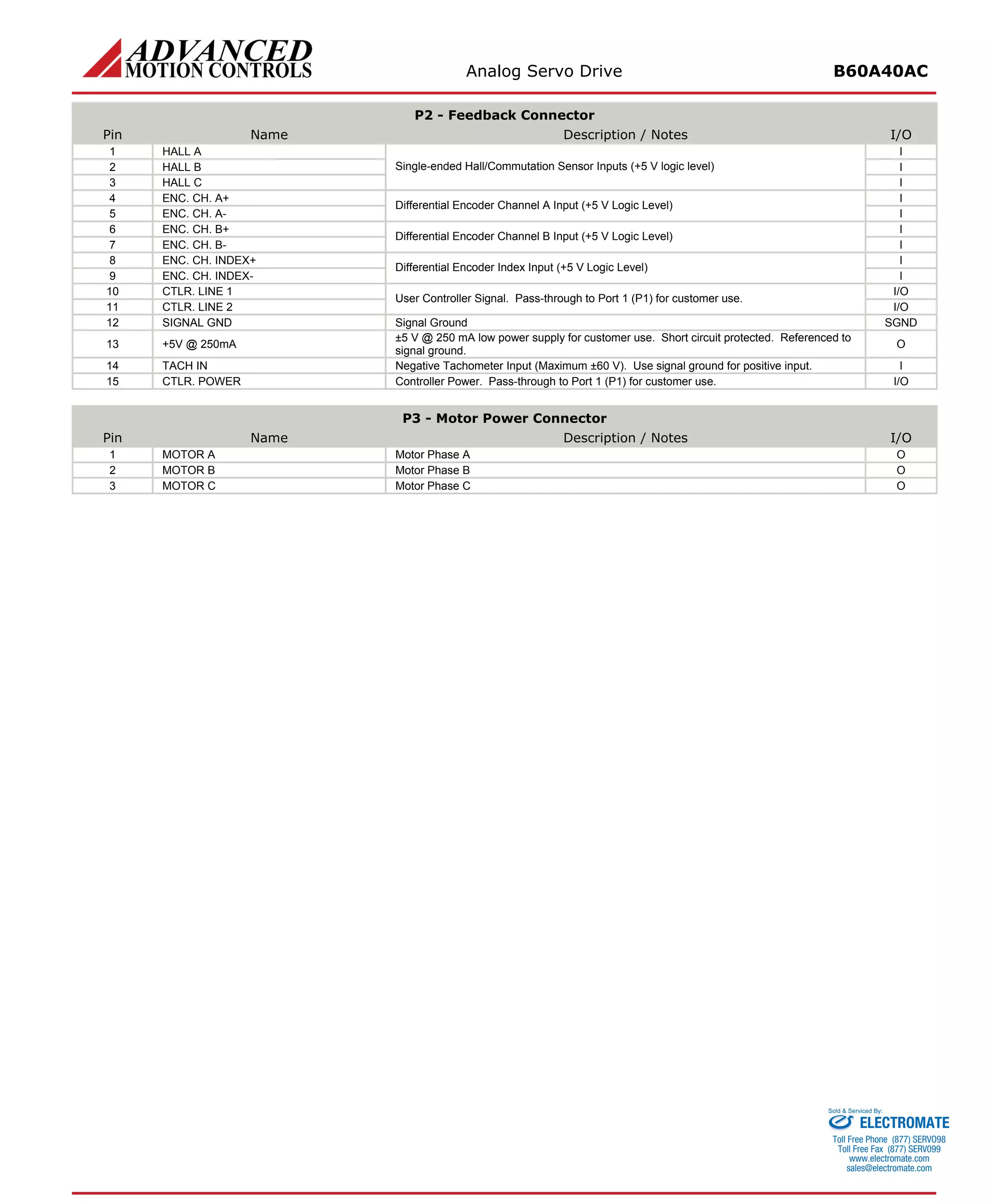
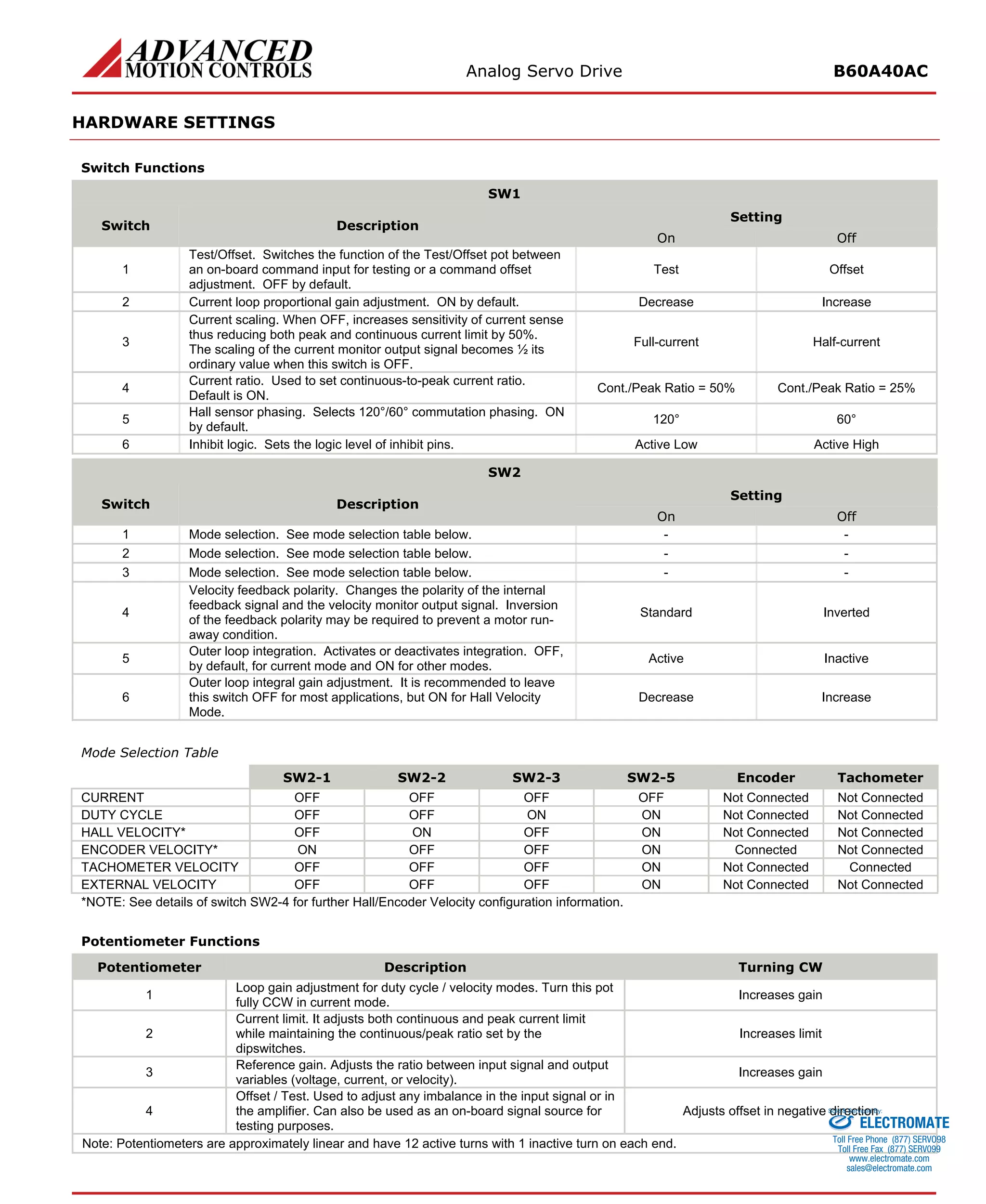
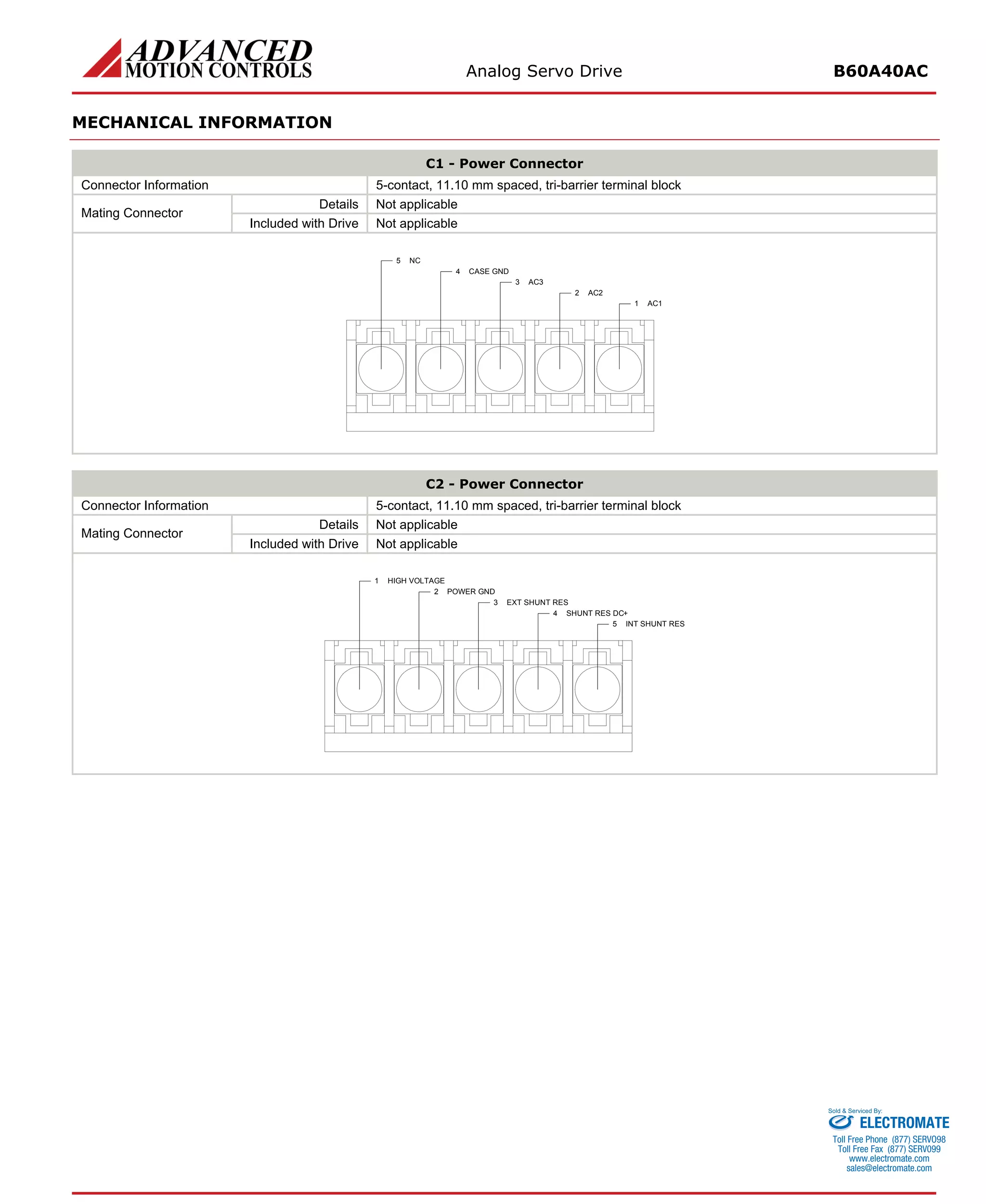
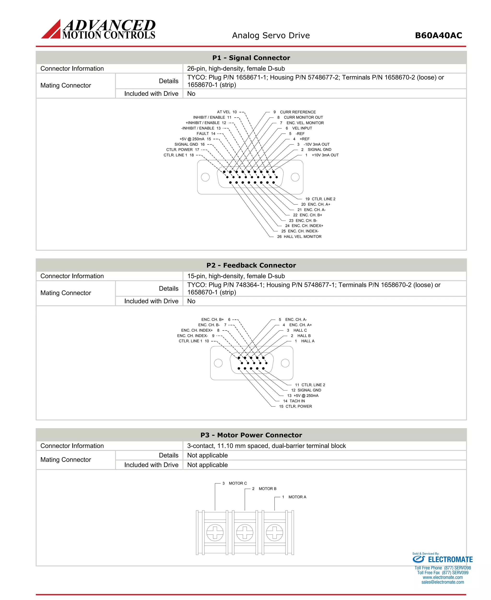

The document describes an analog servo drive that: - Can provide up to 60A of peak current and 30A of continuous current from a 45-265VAC power supply. - Includes protection against overvoltage, undervoltage, overcurrent and other faults. - Can be controlled via analog input or standalone and supports hall sensors, encoders or tachometers for feedback. - Has adjustable parameters for current limit, gain and offset via potentiometers.


![Coded Agents – with UiPath SDK + LangGraph [Virtual Hands-on Workshop]](https://cdn.slidesharecdn.com/ss_thumbnails/codedagentsdeck-251215155422-5497c599-thumbnail.jpg?width=640&height=640&fit=bounds)


