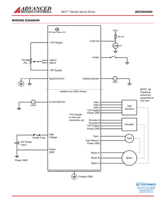
This servo drive amplifier can provide up to 250A of peak current and 150A of continuous current. It is designed to drive brushless DC motors and interface with digital controllers. It has protection against overheating, overcurrent and other faults. Operating modes include current control, velocity control using encoders or Hall sensors, and it can drive brushed or brushless motors.
This servo drive is designed to drive brushless DC motors at high power levels. It can operate in various modes including current, velocity, and duty cycle modes. It has protections against overheating, overcurrent and other faults. It is compliant with various safety standards and has adjustable parameters, feedback options and I/O for control and monitoring.
This document provides information on the M/VTM Series Servo Drive AB100C200. It summarizes the drive's key specifications including its power range, features, modes of operation, command sources, feedback supported, and agency approvals. The document also includes block diagrams, pinout diagrams, switch settings, and other technical details.
This document provides information on the M/VTM Series Servo Drive AB125A200. It is a brushless DC motor amplifier that can deliver up to 125A of peak current and 80A of continuous current. It has various operating modes including current, velocity, and duty cycle. It supports feedback from Hall sensors, encoders, and tachometers. Hardware settings like switches and potentiometers allow adjusting parameters like current limits and loop gains.
This document provides specifications for the M/VTM Series Servo Drive AVB250A060. It is designed to drive brushless DC motors for vehicle applications with a peak current of 250A and continuous current of 150A. It has adjustable parameters, fault protection, and can accept various command and feedback inputs. It is compliant with various safety and environmental standards.
The document describes the M/VTM Series Servo Drive AVB200A100. It is designed to drive brushless DC motors for vehicle applications with a peak current of 200A and continuous current of 125A. It can interface with digital controllers or operate independently, accepting various command and feedback inputs. Key features include adjustable parameters, operating mode selection, and safety protections.
This document provides specifications for the M/VTM Series Servo Drive AVB125A200. It is designed to drive brushless DC motors for vehicle applications with a peak current of 125A and continuous current of 80A. It accepts analog and potentiometer command inputs and feedback from Hall sensors, encoders, or tachometers. Modes of operation include current, voltage, velocity control and more which are selected using onboard DIP switches and potentiometers.
The document describes a servo drive model AVB100C200 that is designed to drive brushless DC motors for vehicle applications. It can interface with digital controllers or operate independently, accepts various feedback types, and has adjustable parameters. The drive has overcurrent, overvoltage, and other protections. It is compliant with various safety and environmental standards.
The document describes an analog servo drive called the BE25A20I. It has the following key specifications:
- It can provide up to 25A of peak current and 12.5A of continuous current.
- It is designed to drive brushless DC motors and can operate in various modes like current, duty cycle, and velocity modes.
- It has protections against overheating, overvoltage, undervoltage, and short circuits.
- It can interface with encoders, Hall sensors, or tachometers for motor feedback and supports motors with three phases.
The document describes an analog servo drive that:
- Can provide up to 60A of peak current and 30A of continuous current from a 45-265VAC power supply.
- Includes protection against overvoltage, undervoltage, overcurrent and other faults.
- Can be controlled via analog input or standalone and supports hall sensors, encoders or tachometers for feedback.
- Has adjustable parameters for current limit, gain and offset via potentiometers.
The document describes the Analog Servo Drive AZBH10A20, which is designed to drive brushless and brushed DC motors. It can provide up to 10A of peak current and 6A of continuous current, operating from 40-175VDC. The drive has features like four quadrant regenerative operation, direct PCB integration, fault monitoring, and supports Hall sensors or tachometers for feedback and various modes of operation.
The document describes the Analog Servo Drive S100A20. It is designed to drive 3-phase brushless motors with sine wave current control. It interfaces directly with digital controllers and requires only a single unregulated DC power supply. It provides fully protected operation and indicators for status.
The document provides specifications for the S60A40AC analog servo drive. It is designed to drive 3-phase brushless motors with sinusoidal current at high switching frequencies. The drive requires two 120-degree phase shifted sine wave command signals for motor control. It has over-current, over-voltage and short circuit protections. Key features include 4-quadrant regenerative operation, adjustable current limits and a built-in brake/shunt regulator.
The document provides specifications for the S30A40AC analog servo drive. It is designed to drive 3-phase brushless motors with sine wave current at high frequencies. It requires two 120-degree phase shifted sine wave command signals for commutation and torque control. The drive has overcurrent, overvoltage, and thermal protections. It is compliant with various safety and EMC standards.
The document describes an analog servo drive that has the following key specifications:
- It can provide a peak current of 20A and continuous current of 10A from a 40-140VDC power supply.
- It is designed to drive brush DC motors at a high switching frequency of 22kHz.
- It has protection against overvoltage, undervoltage, overcurrent, overheating and short circuits.
The S60A40 PWM servo drive is designed to drive 3-phase brushless motors with sinusoidal current. It interfaces with digital controllers and requires 2 sinusoidal command signals with 120° phase shift for motor commutation. The drive is fully protected and requires only a single DC power supply. It provides optical isolation between high and low power signals.
The Analog Servo Drive 10A8 is a PWM servo amplifier designed to drive brush DC motors with a peak current of 10A and continuous current of 6A. It operates from 20-80VDC and has full protection against overcurrent, overheating and short circuits. It can be used with digital controllers or standalone and interfaces with ±10V analog command signals.
The document describes an analog servo drive called the BE40A20I. It has the following key specifications:
- It can provide a peak current of 40A and continuous current of 20A from a 40-190VDC power supply.
- It is designed to drive brushless DC motors and supports various feedback types including halls sensors and encoders.
- It has protection against overvoltage, undervoltage, overcurrent and other faults. It also has adjustable parameters like current limits and gains.
The S30A40 analog servo drive is designed to drive 3-phase brushless motors with sine wave current. It interfaces with digital controllers and requires 2 sinusoidal command signals with 120° phase shift for motor commutation. The drive provides protection against overvoltage, overcurrent and other faults. It operates from a single DC power supply and has optical isolation between high and low power signals.
The document provides specifications for the Analog Servo Drive 100A25. It is designed to drive brush DC motors with a peak current of 100A and continuous current of 50A. It can interface with digital controllers or operate standalone, and includes protections against overvoltage, overcurrent and other faults. The drive can be configured through dip switches and potentiometers to operate in different modes including current, velocity and voltage control.
The document provides specifications for the S100A40AC analog servo drive. The drive is designed to drive 3-phase brushless motors with sine wave current at high switching frequency, requiring 2 sinusoidal command signals with 120-degree phase shift. It has a peak current of 100A, continuous current of 50A, and supply voltage range of 45-270VAC. The drive includes protective features and status indicators.
The document provides specifications for the AZBH25A20 analog servo drive. The drive is designed to drive brushless and brushed DC motors at high switching frequencies. It has a peak current of 25A, continuous current of 12.5A, and operates on a DC supply voltage of 40-175VDC. The drive provides various protection features and supports different feedback and operation modes.
The document describes the Analog Servo Drive B100A400AC, which is designed to drive brushless DC motors at high switching frequencies. It can interface with digital controllers or operate standalone, and accepts various feedback types including encoders and Hall sensors. The drive has overcurrent, overvoltage, and other protections, and can operate in different modes such as current, voltage, and encoder velocity modes using analog command inputs.
The S100A8 analog servo drive is designed to drive 3-phase brushless motors with sinusoidal current. It interfaces with digital controllers and requires 2 sinusoidal command signals 120 degrees out of phase. It has protection against overvoltage, overcurrent, and short circuits. Key features include optical isolation, regenerative braking, adjustable current limits, and a high switching frequency.
The AZXBE6C20 analog servo drive is designed to drive brushless DC motors at high switching frequencies. It is fully protected against over-voltage, over-current and other faults. The drive can utilize encoder or tachometer feedback for velocity control and interfaces with digital controllers that have analog ±10V outputs. It is designed for wide temperature ranges and direct integration into PCBs.
The S60A8 analog servo drive is designed to drive 3-phase brushless motors with sinusoidal current. It requires 2 sinusoidal command signals 120 degrees out of phase to control motor position and torque. The drive interfaces with digital controllers, has overvoltage, overcurrent, and overheating protections, and operates from a single DC power supply. It provides optical isolation between high and low power signals.
The S100A40 analog servo drive is designed to drive 3-phase brushless motors with sinusoidal current. It interfaces with digital controllers and requires 2 sinusoidal command signals with 120° phase shift for motor commutation. The drive provides full motor and system protection, and all signal inputs and outputs are optically isolated from the power section. It is compliant with various safety and EMC standards.
The ZBE12A8 analog servo drive can provide up to 12A of continuous current to drive brushless DC motors. It has various protection features and operating modes that can be selected with switches and pots. It interfaces with external controllers through analog voltage commands and supports feedback from hall sensors or encoders.
The document describes an analog servo drive called the BE25A20FAC. It has the following key specifications:
- It can deliver up to 25A of peak current and 12.5A of continuous current from a 30-130V AC power supply.
- It is designed to drive brushless DC motors and features four quadrant regenerative operation, adjustable current limits, and selectable operating modes including current, open loop, and encoder velocity modes.
- It provides motor commutation from hall sensors or an encoder, and supports feedback from halls, encoders, or a tachometer.
- It has adjustable parameters like loop gain, current limit, input gain and offset via onboard potentiometers.
The AZB25A20 analog servo drive is designed to drive brushless and brushed DC motors. It has a peak current of 25A, continuous current of 12.5A, and operates on a supply voltage of 40-175VDC. It provides protection against overvoltage, undervoltage, overcurrent, overheating and short circuits. The drive can be directly integrated into PCBs and interfaces with digital controllers that have analog ±10V outputs.
The LDK is a compact linear encoder that uses optical diffraction technology. It has resolutions up to 2500 counts per inch and travels up to 48 inches. It comes with different scale and cable options and has a operating temperature range of -25°C to 85°C.
This document provides specifications for the DigiFlex® PerformanceTM Servo Drive DPRAHIE-060A400. It can supply up to 60A of peak current and 30A of continuous current from a 100-240VAC power supply. It has various inputs and outputs to interface with motors, encoders, and external controllers. It supports brushless, brushed, and single phase motors and operates in multiple modes including current, position, velocity and hall velocity control.
The SRST Series shunt regulators are designed to work with ADVANCED MOTION CONTROL's four quadrant regenerative servo amplifiers. They dissipate excess energy during braking to prevent amplifier over voltage shutdown. Models are available with shunt voltages from 50 to 400 volts and include a power resistor and filter capacitor. They mount on a base plate for easy installation.
The document discusses LINTECH's precision positioning components including:
- Precision steel and stainless steel shafts for use in shaft assemblies. Shafts are hardened and ground for smoothness.
- Shaft assemblies (SA and TRSA series) that mount shafts to aluminum supports for easy installation.
- Linear bearings and pillow blocks that support shafts. Bearings use steel balls and plates and have high load capacity. Pillow blocks house one or two bearings.
The document provides information on the 120A10 series PWM servo amplifiers from Electromate. The amplifiers are designed to drive brush DC motors and feature surface mount technology, optical isolation, and DIP switch selectable modes including current, voltage, velocity, and IR compensation. Key specifications include a 30-80V DC supply voltage, 120A peak current, 15kHz switching frequency, and 10x5.12x2.63 inch dimensions. The amplifiers have 16-pin connectors for signals and power and include features like adjustable loop gain, current limit, input gain, and offset.
The document provides information on the maxon DC-max brushed DC motors. It describes their key features such as strong neodymium magnets, state-of-the-art winding technology, and cost-optimized design. Specifications are given for different DC-max motor sizes, including their power ratings, speed, torque, dimensions, and electrical characteristics. The document also briefly introduces maxon motor as a leading provider of precision drives and systems.
The Model HD2 is an incremental optical rotary encoder designed for rugged applications. It has features such as a 100,000 hour MTBF LED light source, high shock tolerance, and high frequency response. It is available with different housing configurations and mounting options. For applications with noise or long cable runs, it can be supplied with an RS422 line driver for improved signal quality over long distances.
This document provides specifications for HPG series input shaft gear units, including:
- Sizes range from 11 to 65 and reduction ratios from 3:1 to 50:1.
- Features include high efficiency up to 97%, low backlash less than 3 arc-minutes as standard or less than 1 arc-minute optional, and a cross roller bearing integrated into the output flange.
- Tables provide details on torque ratings, speeds, inertia, mass, accuracy, repeatability, and stiffness for each size.
Galil Ethernet or EtherCAT Motion Control Webinar January 26, 2016Electromate
This document discusses choosing between Ethernet and EtherCAT networks for motion control applications. It provides an overview of centralized vs distributed control systems, describes the key differences between Ethernet and EtherCAT at the hardware level, and gives examples of Galil motion controllers and I/O modules that support both network types. A decision tree is presented outlining considerations for determining whether EtherCAT or Ethernet is best for a given application.
This document discusses harmonic drive and planetary gearheads for servo motors. It describes two main product lines: 1) Harmonic Planetary gearheads that use 3-4 planet carriers with ratios from 3:1 to 50:1, and 2) Harmonic Drive gearheads that use elasto-mechanical wave reduction technology with higher ratios from 50:1 to 160:1. The document provides details on several gearhead models within these product lines and specifies their characteristics such as backlash, accuracy, repeatability, frame sizes, ratios, and pricing/lead times.
The document discusses high-performance gearheads for servomotors. It provides specifications for the CSF-GH series including size options, torque ratings at different speeds, accuracy and repeatability levels, stiffness values, dimensions and other technical details. Tables provide rated torque values, stiffness coefficients, accuracy and repeatability data for the various gearhead sizes.
This document provides specifications for a 120W DIN rail power supply with the following key details:
- It has a single 120W output with a voltage range of 22-28V and a current of 5A.
- The input voltage range is 85-264VAC. It has protections such as overload, overvoltage, and overtemperature protections.
- Additional features include compact design, easy wire connection, 10 year lifetime, shock/vibration resistance, and convection cooling.
Applied motion products txm24 c brochureElectromate
This document is a hardware manual for the TXM24C Integrated Step-Servo Motor. It provides information on features, installation, connections, troubleshooting and specifications. Key features include programmable servo control, CANopen and RS-232 communications, digital and analog inputs/outputs, and IP65 protection. Installation instructions cover choosing a power supply, mounting, and connecting power, communications and I/O. Safety precautions and specifications are also included.
Micro e systems_data_sheet-veratus_series_preliminaryElectromate
The document describes the Veratus Series encoders from MicroE. It provides specifications for the compact precision encoders including dimensions, resolution options, accuracy, interfaces, environmental tolerances, and mounting configurations. Key features highlighted are the encoders' reliability, signal stability, and tolerance to contamination due to their VeraPath technology.
Micro e systems_data_sheet-optira_series_preliminary_v2Electromate
The document provides product information for MicroE's Optira Series encoders. The Optira encoders offer miniature precision encoding in a package as small as 11.4 x 13 mm. They provide resolutions up to 5 nm with signal processing performed in the sensor head. The encoders have various output and connectivity options and are compatible with MicroE's linear and rotary grating scales, making them suitable for miniature motion control and precision instrument applications.
The document describes the Analog Servo Drive B060A400AC, which is designed to drive brushless DC motors at high switching frequencies. It can interface with digital controllers or operate standalone, accepting various feedback types. It has multiple operating modes and protections, and can be configured using DIP switches and potentiometers for parameters like current limit and loop gain.
The document describes an analog servo drive that:
- Can provide up to 60A of peak current and 30A of continuous current from a 60-400VDC power supply.
- Includes protection against overvoltage, overcurrent, overheating and other faults.
- Can be controlled via a ±10V analog command and supports Hall, encoder and tachometer feedback.
- Has adjustable current limits, acceleration/deceleration rates, and other parameters via onboard potentiometers.
The document describes an analog servo drive that provides:
- Peak current of 100A and continuous current of 50A
- Adjustable settings for loop gain, current limit, input gain and offset using potentiometers
- Multiple operation modes including current, duty cycle, hall velocity and encoder velocity
- Protection against overvoltage, undervoltage, overcurrent and other faults
The B30A40 PWM servo drive is designed to drive brushless DC motors with a peak current of 30A and continuous current of 15A. It can interface with digital controllers or operate stand-alone, and includes protections against overheating, overcurrent, and other faults. The drive allows adjusting parameters like current limit, input gain, and offset using on-board potentiometers, and supports Hall, encoder, and tachometer feedback.
The document describes an analog servo drive model B100A8. It can provide up to 100A of peak current and 50A of continuous current from a 20-80VDC power supply. It is designed to drive brushless DC motors and features adjustable current limits, gain, and offset settings. It supports Hall sensor, encoder, and tachometer feedback and can operate in various modes including current and velocity control.
The document describes the Analog Servo Drive BE30A8. It can provide up to 30A of peak current and 15A of continuous current from a 20-80VDC power supply. It is designed to drive brushless DC motors and protects against overloads. It has adjustable settings for current, velocity control, and commutation using potentiometers and dip switches.
The document describes an analog servo drive that:
- Can provide up to 40A of peak current and 20A of continuous current from a 60-400VDC power supply.
- Drives brushless DC motors and has operating modes including current, duty cycle, hall velocity and encoder velocity.
- Includes protections such as overvoltage, undervoltage and overcurrent protections.
- Can interface with digital controllers or operate stand-alone and has adjustable parameters using potentiometers.
This document provides information about the Analog Servo Drive BE25A20AC:
1) It is a PWM servo drive designed to drive brushless DC motors at high switching frequencies up to 25A of peak current and 12.5A of continuous current.
2) It has fully adjustable current and velocity control loops as well as protective features against overloads and faults.
3) The drive can operate in different modes such as current control, duty cycle control and encoder velocity control using potentiometers and DIP switches for configuration.
The document describes an analog servo drive that:
- Can provide up to 40A of peak current and 20A of continuous current from a 45-265VAC power supply.
- Includes protection against overvoltage, undervoltage, overcurrent, overheating and short circuits.
- Can be controlled via analog input, encoder, or hall sensors and has adjustable current limits, gains and offsets.
- Has DIP switches to select modes of operation and feedback and includes monitoring outputs.
The SX30A8 analog servo drive:
- Is designed to drive 3-phase brushless motors with sinusoidal current control. It requires two 120° phase shifted sine wave command signals.
- Has a peak current of 30A and continuous current of 15A RMS. It operates from a 20-80VDC power supply.
- Provides optical isolation, regenerative braking, adjustable current limits, and fault protection. Status is indicated by an LED and digital outputs.
The document describes the Analog Servo Drive B25A20AC. It is designed to drive brushless DC motors with a peak current of 25A and continuous current of 12.5A. It can operate on a single 30-125VAC power supply and has protection against overvoltage, overcurrent, and other faults. It provides adjustable current limits and loop gains using on-board potentiometers and can interface with digital controllers or operate standalone.
The AZBH20A8 analog servo drive is designed to drive brushless and brushed DC motors at high switching frequencies. It can provide up to 20A of peak current and 12A of continuous current from a 10-80VDC power supply. The drive offers various protection features and operation modes, and integrates directly into PCBs for compact designs.
The document describes an analog servo drive that provides peak currents of 100A and continuous currents of 50A. It has various operating modes and feedback options. It is fully protected against overloads and faults. Potentiometers and switches allow adjusting parameters like current limits and gains.
The document describes the Analog Servo Drive AZBH40A8. It is designed to drive brushless and brushed DC motors at high switching frequencies. It can provide a peak current of 40A and continuous current of 20A, with a supply voltage range of 10-80VDC. The drive supports various feedback and operation modes, and includes protections for overvoltage, overcurrent, overheating and more.
The document provides specifications for the AZBE25A20 analog servo drive. The drive is designed to drive brushless and brushed DC motors at high switching frequencies up to 25A continuous current. It has features like four quadrant regenerative operation, direct board integration, encoder and tachometer feedback support, and hardware protections. The drive requires only a single DC power supply and complies with safety and emissions standards.
Similar to Advanced motion controls ab250a060 (15)
Automated screw thread quality checking using SMAC LAR55 actuator new produc...Electromate
The document discusses an automated screw thread quality checking solution using SMAC LAR55 actuators. It allows 100% inspection of screw threads to check for issues like oversizing, cross-threading, depth, and pitch. This can help automakers meet higher quality standards by eliminating defective parts and providing immediate feedback. The LAR55's precision Z-theta motion makes it suitable for automatically checking screw threads.
An overview of the various kinematic models in both parallel and serial robot...Electromate
This document provides an overview of kinematic models for parallel and serial robotic mechanisms and their suitability for precision applications. It introduces Ilian Bonev, a professor at École de technologie supérieure who is an expert in parallel robots and precision robotics. It then describes some parallel robots that have been developed at the Control and Robotics Laboratory including ones for medical, manufacturing, and research applications. The document concludes with sections on robot calibration methods and the differences between serial and parallel mechanisms.
Galil motion control robotic symposium presentation-linear motion from non-li...Electromate
The document discusses non-linear robotic motion control solutions. It describes how Galil Motion Control provides controllers for various types of non-linear robots like SCARA and delta robots. It covers topics like selecting the robot topology, designing each joint, motor selection, forward and inverse kinematics equations, vibration reduction techniques, and examples of implementing motion control for SCARA robots.
Advanced motion controls robotics symposium presentation-open standard tools ...Electromate
This document discusses the development of control software for a linear delta robot used in 3D printing. It describes using PLCopen function blocks and XML files to create reusable software components for robot kinematics and handling G-code from slicing programs. Function block diagrams are created to process G-code, set coordinate systems, and represent the overall project logic. The solution involves creating user-defined function blocks to handle the robot's inverse kinematics and translate G-code commands into motions.
Maxon motor ag robotic symposium presentation-impedance control overview and ...Electromate
The document discusses impedance control, an approach to robot control that models mechanical systems as electrical circuits using impedance. It defines electrical and mechanical impedance analogously and describes how components like resistors, inductors, and capacitors correspond to dampers, masses, and springs physically. The document outlines applications of impedance control and emphasizes the importance of selecting low-inertia motors, high-efficiency gears, and fast, accurate sensors and controllers. Overall, the document argues that impedance control requires creative engineering of mechanical designs and electrical components.
Kollmorgen robotic symposium presentation-motor design impacts on the optimiz...Electromate
The document discusses how motor design impacts the optimization of robotic systems. It explains that frameless motors can enable smaller, lighter and faster robots through their direct drive capabilities and high torque density. The document also covers various motor topologies and important concepts like torque constant, motor size constant, and how they relate to continuous torque capacity, efficiency and losses. Application examples discussed include collaborative robots, surgical robots, and mobile robots.
Harmonic drive llc robotics symposium presentation-designing from the inside ...Electromate
The document discusses defining robot performance requirements and how customized solutions from Harmonic Drive can help meet those requirements. It provides an overview of Harmonic Drive's product line and gear technologies, then discusses how mechanical modifications and performance customizations can be made to their gear components and systems to optimize robots for specific design requirements and applications. Customizations like increased accuracy, stiffness, torque properties and materials can be made, with varying levels of difficulty and cost implications discussed.
Thomson Linear Dual Shaft Rail 2DA Modular SpecsElectromate
This document provides specifications and dimensional drawings for Thomson Industries' Dual Shaft Rail linear guides with modular carriages. It includes part numbers, dimensions, load ratings and descriptions of the components. Linear guides use dual linear race shaft rails and modular carriages with open type Super Smart Ball Bushings. They are used in continuously supported applications requiring rigidity and are adaptable to any drive system.
Thomson Linear 2DA QuickSlide System with BrakeElectromate
This document provides specifications for Thomson Industries' 2DA QuickSlide system with brake, including:
- It offers manual locking with infinite positioning, no carriage surface deflection when locked, and immediate availability in common sizes.
- The locking mechanism does not increase load on the bearing and allows zero axial movement during locking.
- It provides a fully supported dual shaft assembly for maximum rigidity and unlimited travel.
Thomson Linear RoundRail 2CA Web Universal Carriage SpecsElectromate
This document contains specifications for Thomson Industries' Twin Shaft Web Linear Guide system. It includes dimensions, part numbers, load ratings and descriptions of the components. The linear guides use a double shaft and welded web design for improved torque strength and deflection characteristics. They are designed to move medium loads with low friction and are commonly used when bridging gaps.
Thomson Linear RoundRail 1VC Double End Supported SpecsElectromate
The document provides specifications for various FluoroNyliner linear guide components including:
- Pillow blocks, twin pillow blocks, shaft end support blocks, and mounting table tops for different size linear guides ranging from 0.375 to 1.5 inches in diameter.
- It lists the part numbers, dimensions, materials, weights, and other specifications for each component.
- It also includes an illustration of a double end supported linear guide system with pillow blocks, shafts, end supports, and a size B mounting table top.
Thomson Linear RoundRail 2CA Web Flanged Carriage SpecsElectromate
This document provides specifications for Thomson Industries' Twin Shaft Web Linear Guide system. It includes dimensions, load capacity information, and part numbers for various components of the 2CA linear guide, which features a flanged carriage design and double linear race shaft for improved torque and deflection characteristics. Configuration and installation details are also listed.
Thomson Linear RoundRail Twin Shaft Web 2CAElectromate
The document provides specifications for Thomson RoundRail linear guides and components. It includes dimensions, features, and part numbering for twin shaft web linear guides in both vertical and horizontal configurations ranging from 0.5 to 1 inch in diameter. Load capacity charts are provided for different guide sizes and configurations that can support loads between 165 to 3000 pounds depending on the model. Maximum guide lengths are listed as 72 inches and engineering calculations for shaft deflection are also noted.
Thomson Linear RoundRail 1VC Double Unsupported SpecsElectromate
The document contains specifications for various FluoroNyliner linear guide parts, including dimensions, part numbers, materials, load ratings, and performance notes. It lists 14 different linear guide parts with nominal diameters ranging from 0.375 to 1.5 inches. For each part, it provides dimensions for components like bearing blocks, carriages, and table tops. It also includes general information on specifying linear guides and product notes on materials and lubrication.
The Thomson WhisperTrak electric linear actuator offers a compact, quiet, and durable solution for applications requiring linear motion. It is particularly well-suited for personal mobility, medical, and rehabilitation equipment due to its small size and silent operation. The actuator provides reliable, maintenance-free movement and has an IP67 rating, making it protected against water and dust. Its flexibility and high performance in a small package make it suitable for a wide range of industries.
The document provides information on the T-Series Ball Profile Rail from Thomson, including:
- It is lightweight, highly flexible, and forgiving, making it suitable for applications with poor misalignment.
- It has a low cost of installation as it can be mounted directly to non-machined bases without special tools.
- It offers industry standard dimensions and dimensions interchangeable with other rail brands, allowing for easy replacement.
Thomson Linear RoundRail Accessories Collapsable Bellows SpecsElectromate
This document provides specifications for various bellows that can be used to protect slides and shafts. It lists different part numbers for bellows with a range of nominal shaft diameters from 1/4 to 1 1/2 inches. The bellows are made of polyester cover and PVC stiffeners. Dimensions such as length, width, and height are provided for each part number. Some bellows are single shaft while others are dual shaft or for horizontal vs vertical systems. Each bellows comes with attachment pieces like Velcro or mounting brackets.
Thomson Linear Roundrail Dual Shaft Rail 2DA SpecsElectromate
The document provides specifications for Danaher Motion's dual shaft rail linear guides with integrated carriages. It includes dimensions, load ratings, dynamic capacities, and part numbering for the 2DA series linear guides available in nominal diameters of 0.5, 0.75, and 1.0 inches. Both full and short length carriage options are detailed along with components, material specifications, and the supplier contact information.
Thomson Linear RoundRail Continuous Support 1PC SpecsElectromate
This document provides specifications for various linear guide assemblies with table tops from Thomson Industries. It includes dimensions, part numbers, load ratings and limit data for single rail linear guides with sizes ranging from M12 to M40 diameter in configurations with 4 pillow blocks, 2 twin pillow blocks or no pillow blocks and size E or F table tops. Mounting details and specifications are provided for the various components including rails, pillow blocks and table tops.
Thomson Linear RoundRail Continuous Support 1PB SpecsElectromate
The document contains specifications for various continuously supported linear guide assemblies and their components. It lists part numbers, dimensions, load ratings, and other technical specifications for linear guides, support rails, pillow blocks, and bearings. Materials include aluminum alloys and bearings include ball bushings. Linear guides are specified by part number plus length and provide continuous support for applications requiring rigidity.
Removing Uninteresting Bytes in Software FuzzingAftab Hussain
Imagine a world where software fuzzing, the process of mutating bytes in test seeds to uncover hidden and erroneous program behaviors, becomes faster and more effective. A lot depends on the initial seeds, which can significantly dictate the trajectory of a fuzzing campaign, particularly in terms of how long it takes to uncover interesting behaviour in your code. We introduce DIAR, a technique designed to speedup fuzzing campaigns by pinpointing and eliminating those uninteresting bytes in the seeds. Picture this: instead of wasting valuable resources on meaningless mutations in large, bloated seeds, DIAR removes the unnecessary bytes, streamlining the entire process.
In this work, we equipped AFL, a popular fuzzer, with DIAR and examined two critical Linux libraries -- Libxml's xmllint, a tool for parsing xml documents, and Binutil's readelf, an essential debugging and security analysis command-line tool used to display detailed information about ELF (Executable and Linkable Format). Our preliminary results show that AFL+DIAR does not only discover new paths more quickly but also achieves higher coverage overall. This work thus showcases how starting with lean and optimized seeds can lead to faster, more comprehensive fuzzing campaigns -- and DIAR helps you find such seeds.
- These are slides of the talk given at IEEE International Conference on Software Testing Verification and Validation Workshop, ICSTW 2022.
Let's Integrate MuleSoft RPA, COMPOSER, APM with AWS IDP along with Slackshyamraj55
Discover the seamless integration of RPA (Robotic Process Automation), COMPOSER, and APM with AWS IDP enhanced with Slack notifications. Explore how these technologies converge to streamline workflows, optimize performance, and ensure secure access, all while leveraging the power of AWS IDP and real-time communication via Slack notifications.
UiPath Test Automation using UiPath Test Suite series, part 5DianaGray10
Welcome to UiPath Test Automation using UiPath Test Suite series part 5. In this session, we will cover CI/CD with devops.
Topics covered:
CI/CD with in UiPath
End-to-end overview of CI/CD pipeline with Azure devops
Speaker:
Lyndsey Byblow, Test Suite Sales Engineer @ UiPath, Inc.
Cosa hanno in comune un mattoncino Lego e la backdoor XZ?Speck&Tech
ABSTRACT: A prima vista, un mattoncino Lego e la backdoor XZ potrebbero avere in comune il fatto di essere entrambi blocchi di costruzione, o dipendenze di progetti creativi e software. La realtà è che un mattoncino Lego e il caso della backdoor XZ hanno molto di più di tutto ciò in comune.
Partecipate alla presentazione per immergervi in una storia di interoperabilità, standard e formati aperti, per poi discutere del ruolo importante che i contributori hanno in una comunità open source sostenibile.
BIO: Sostenitrice del software libero e dei formati standard e aperti. È stata un membro attivo dei progetti Fedora e openSUSE e ha co-fondato l'Associazione LibreItalia dove è stata coinvolta in diversi eventi, migrazioni e formazione relativi a LibreOffice. In precedenza ha lavorato a migrazioni e corsi di formazione su LibreOffice per diverse amministrazioni pubbliche e privati. Da gennaio 2020 lavora in SUSE come Software Release Engineer per Uyuni e SUSE Manager e quando non segue la sua passione per i computer e per Geeko coltiva la sua curiosità per l'astronomia (da cui deriva il suo nickname deneb_alpha).
Climate Impact of Software Testing at Nordic Testing DaysKari Kakkonen
My slides at Nordic Testing Days 6.6.2024
Climate impact / sustainability of software testing discussed on the talk. ICT and testing must carry their part of global responsibility to help with the climat warming. We can minimize the carbon footprint but we can also have a carbon handprint, a positive impact on the climate. Quality characteristics can be added with sustainability, and then measured continuously. Test environments can be used less, and in smaller scale and on demand. Test techniques can be used in optimizing or minimizing number of tests. Test automation can be used to speed up testing.
In the rapidly evolving landscape of technologies, XML continues to play a vital role in structuring, storing, and transporting data across diverse systems. The recent advancements in artificial intelligence (AI) present new methodologies for enhancing XML development workflows, introducing efficiency, automation, and intelligent capabilities. This presentation will outline the scope and perspective of utilizing AI in XML development. The potential benefits and the possible pitfalls will be highlighted, providing a balanced view of the subject.
We will explore the capabilities of AI in understanding XML markup languages and autonomously creating structured XML content. Additionally, we will examine the capacity of AI to enrich plain text with appropriate XML markup. Practical examples and methodological guidelines will be provided to elucidate how AI can be effectively prompted to interpret and generate accurate XML markup.
Further emphasis will be placed on the role of AI in developing XSLT, or schemas such as XSD and Schematron. We will address the techniques and strategies adopted to create prompts for generating code, explaining code, or refactoring the code, and the results achieved.
The discussion will extend to how AI can be used to transform XML content. In particular, the focus will be on the use of AI XPath extension functions in XSLT, Schematron, Schematron Quick Fixes, or for XML content refactoring.
The presentation aims to deliver a comprehensive overview of AI usage in XML development, providing attendees with the necessary knowledge to make informed decisions. Whether you’re at the early stages of adopting AI or considering integrating it in advanced XML development, this presentation will cover all levels of expertise.
By highlighting the potential advantages and challenges of integrating AI with XML development tools and languages, the presentation seeks to inspire thoughtful conversation around the future of XML development. We’ll not only delve into the technical aspects of AI-powered XML development but also discuss practical implications and possible future directions.
Enchancing adoption of Open Source Libraries. A case study on Albumentations.AIVladimir Iglovikov, Ph.D.
Presented by Vladimir Iglovikov:
- https://www.linkedin.com/in/iglovikov/
- https://x.com/viglovikov
- https://www.instagram.com/ternaus/
This presentation delves into the journey of Albumentations.ai, a highly successful open-source library for data augmentation.
Created out of a necessity for superior performance in Kaggle competitions, Albumentations has grown to become a widely used tool among data scientists and machine learning practitioners.
This case study covers various aspects, including:
People: The contributors and community that have supported Albumentations.
Metrics: The success indicators such as downloads, daily active users, GitHub stars, and financial contributions.
Challenges: The hurdles in monetizing open-source projects and measuring user engagement.
Development Practices: Best practices for creating, maintaining, and scaling open-source libraries, including code hygiene, CI/CD, and fast iteration.
Community Building: Strategies for making adoption easy, iterating quickly, and fostering a vibrant, engaged community.
Marketing: Both online and offline marketing tactics, focusing on real, impactful interactions and collaborations.
Mental Health: Maintaining balance and not feeling pressured by user demands.
Key insights include the importance of automation, making the adoption process seamless, and leveraging offline interactions for marketing. The presentation also emphasizes the need for continuous small improvements and building a friendly, inclusive community that contributes to the project's growth.
Vladimir Iglovikov brings his extensive experience as a Kaggle Grandmaster, ex-Staff ML Engineer at Lyft, sharing valuable lessons and practical advice for anyone looking to enhance the adoption of their open-source projects.
Explore more about Albumentations and join the community at:
GitHub: https://github.com/albumentations-team/albumentations
Website: https://albumentations.ai/
LinkedIn: https://www.linkedin.com/company/100504475
Twitter: https://x.com/albumentations
For the full video of this presentation, please visit: https://www.edge-ai-vision.com/2024/06/building-and-scaling-ai-applications-with-the-nx-ai-manager-a-presentation-from-network-optix/
Robin van Emden, Senior Director of Data Science at Network Optix, presents the “Building and Scaling AI Applications with the Nx AI Manager,” tutorial at the May 2024 Embedded Vision Summit.
In this presentation, van Emden covers the basics of scaling edge AI solutions using the Nx tool kit. He emphasizes the process of developing AI models and deploying them globally. He also showcases the conversion of AI models and the creation of effective edge AI pipelines, with a focus on pre-processing, model conversion, selecting the appropriate inference engine for the target hardware and post-processing.
van Emden shows how Nx can simplify the developer’s life and facilitate a rapid transition from concept to production-ready applications.He provides valuable insights into developing scalable and efficient edge AI solutions, with a strong focus on practical implementation.
Unlock the Future of Search with MongoDB Atlas_ Vector Search Unleashed.pdfMalak Abu Hammad
Discover how MongoDB Atlas and vector search technology can revolutionize your application's search capabilities. This comprehensive presentation covers:
* What is Vector Search?
* Importance and benefits of vector search
* Practical use cases across various industries
* Step-by-step implementation guide
* Live demos with code snippets
* Enhancing LLM capabilities with vector search
* Best practices and optimization strategies
Perfect for developers, AI enthusiasts, and tech leaders. Learn how to leverage MongoDB Atlas to deliver highly relevant, context-aware search results, transforming your data retrieval process. Stay ahead in tech innovation and maximize the potential of your applications.
#MongoDB #VectorSearch #AI #SemanticSearch #TechInnovation #DataScience #LLM #MachineLearning #SearchTechnology
GraphSummit Singapore | The Art of the Possible with Graph - Q2 2024Neo4j
Neha Bajwa, Vice President of Product Marketing, Neo4j
Join us as we explore breakthrough innovations enabled by interconnected data and AI. Discover firsthand how organizations use relationships in data to uncover contextual insights and solve our most pressing challenges – from optimizing supply chains, detecting fraud, and improving customer experiences to accelerating drug discoveries.
Goodbye Windows 11: Make Way for Nitrux Linux 3.5.0!SOFTTECHHUB
As the digital landscape continually evolves, operating systems play a critical role in shaping user experiences and productivity. The launch of Nitrux Linux 3.5.0 marks a significant milestone, offering a robust alternative to traditional systems such as Windows 11. This article delves into the essence of Nitrux Linux 3.5.0, exploring its unique features, advantages, and how it stands as a compelling choice for both casual users and tech enthusiasts.
In his public lecture, Christian Timmerer provides insights into the fascinating history of video streaming, starting from its humble beginnings before YouTube to the groundbreaking technologies that now dominate platforms like Netflix and ORF ON. Timmerer also presents provocative contributions of his own that have significantly influenced the industry. He concludes by looking at future challenges and invites the audience to join in a discussion.
Introducing Milvus Lite: Easy-to-Install, Easy-to-Use vector database for you...Zilliz
Join us to introduce Milvus Lite, a vector database that can run on notebooks and laptops, share the same API with Milvus, and integrate with every popular GenAI framework. This webinar is perfect for developers seeking easy-to-use, well-integrated vector databases for their GenAI apps.
Introducing Milvus Lite: Easy-to-Install, Easy-to-Use vector database for you...
Advanced motion controls ab250a060
1. M/V™ Series Servo Drive AB250A060
Description
Power Range
AB250A060 servo amplifiers are designed to drive brushless DC motors at a high switching frequency. It is fully protected against over-voltage, over-current, over-heating, under-voltage and short-circuits. This model interfaces with digital controllers or can be used as a stand-alone drive and requires only a single unregulated DC power supply or battery. A single red/green LED and a single digital output indicate operating status. Loop gain, current limit, input gain, and offset can be adjusted using 14-turn potentiometers. The offset adjusting potentiometer can also be used as an on-board input signal for testing purposes. It will accept tachometer input, quadrature encoder inputs, or Hall sensor inputs for velocity control.
Peak Current (10 seconds) 250 A
Continuous Current 150 A
Supply Voltage 20 - 54 VDC
Features
Four Quadrant Regenerative Operation
Ramped Command Input Adjustment
Drive Brushed or Brushless Motors
Compact Size, High Power Density
Selectable 120/60 Hall Commutation Phasing
Offset Adjustment Potentiometer
Ingress Protection Rating: IP65
Selectable Inhibit/Enable Logic
Adjustable Current Limits
Multiple Modes of Operation
MODES OF OPERATION
Current
Voltage
Duty Cycle (Open Loop)
IR Compensation
Velocity
Hall Velocity
COMMAND SOURCE
±10V Analog
FEEDBACK SUPPORTED
Halls
Incremental Encoder
Tachometer (±60 DC)
INPUTS/OUTPUTS
Inhibit/Enable Input
Current Monitor Output
Velocity Monitor Output
Fault Output
COMPLIANCES & AGENCY APPROVALS
UL
cUL
RoHS
CE Pending
ELECTROMATE
Toll Free Phone (877) SERVO98
Toll Free Fax (877) SERV099
www.electromate.com
sales@electromate.com
Sold & Serviced By:
2. M/V™ Series Servo Drive AB250A060
BLOCK DIAGRAM
LOOP INTEGRATORVELOCITYCURRENT LOOPVARIABLERC-BLOCKPOT3POT1ON -RAMPOFF-NO RAMPSW1-5SW1-4SW1-320k10k..310k- + 10k20.8kP1-5PGNDCURRENTSENSEB+ B- NCP1-6PGNDHVINMOTOR BMCMOTOR AMAMBH-BRIDGEMOTOR C3-Phase- + SW1-8 PWM ANDCONTROLLOGICSW1-9 VelDir INH SEL Curr/VelDEGFAULTINH/ENABLE 10nF SW1-2 SW1-7SW3-1..55nF..82nFCF1* DC-TO-DCPeak/Cont. CURRENTLIMITSW3-6..1020k+5VIP1-12INH/ENABLE5k10kCW100k- + 10kCWSW1-10RAMP30k10k1nF20k+REFP1-120k- + 30k10k1nF-REFP1-2SW1-1POT4100k+5V5k-5VOFFSETTESTCWCWMin: 0.1s/VMax: 1.8s/V3.3k10kHALL/ENCCONV. RECOMMENDED SETTINGS FOR CURRENT MODE -POT1 FULLY CCW, POT3 FULLY CWLED GREEN -NORMAL OPERATION, LED RED -FAULTDRIVES ARE SHIPPED IN CURRENT MODE WITH MAXIMUM CURRENT SETTINGS* OPTIONAL USER INSTALLED THROUGH HOLE COMPONENTSFOR OTHER SWITCH FUNCTIONS SEE SWITCH DESCRIPTION10k P1-15 10k10kP1-19SW1-6 50kINTERNALCONVERTERDC-TO-DC+10V USER (3mA)P1-3P1-4-10V USER (3mA) RF2* P1-23P1-22P1-17 N/AONONN/AOFFOFFOFFN/AONOFFN/AONONN/AONSW1-6SW1-7HALL VELOCITYSW1-3MODE SELECTIONCURRENTSW1-5SW1-4N/AOFFOFFXX OFFXX N/A -NOT APPLICABLETACHOMETERX -DEPENDENT ON APPLICATIONOFFIR COMPENSATION** ONENCODER VELOCITYOFFDUTY CYCLEOFFOFFOFFOFF P1-7PGND P1-16P1-10SGNDP1-11SGND P1-8NC 10k P1-13P1-14P1-20P1-21 20k+5VIQ22222P1-18FAULT-OUTFAULTSGNDP1-910kCWLIMITPOT2U34H1,H2,H3ON=120CF2* 2.2uF0.47uFU31AB250A060 FUNCTIONAL BLOCK DIAGRAMCURRENT100kU32U15POT5LOOP GAINU20REF INVELOCITY+5VHEENC A,B H3CURRENT MONITOR VOLTAGE FEEDBACKDUTY CYCLE FEEDBACKIR-COMPENSATIONVELOCITY MODE SELECTORH1,H2,H3ENC A,B CURRENT LOOP OFF=60ON=CMOFF=VMCURRENT FEEDBACK VELOCITY MONITORTACH-IN+5VHE (250mA) H1H2ENCBENCA +5VHERF1* **IR COMPENSATION MODE REQUIRES USER INSTALLED RESISTOR RF1 ON PCBSGNDOFFOFFOFFOFFVOLTAGEX
Information on Approvals and Compliances
US and Canadian safety compliance with UL 508c, the industrial standard for power conversion electronics. UL registered under file number E140173. Note that machine components compliant with UL are considered UL registered as opposed to UL listed as would be the case for commercial products.
RoHS (Reduction of Hazardous Substances) is intended to prevent hazardous substances such as lead from being manufactured in electrical and electronic equipment.
ELECTROMATE
Toll Free Phone (877) SERVO98
Toll Free Fax (877) SERV099
www.electromate.com
sales@electromate.com
Sold & Serviced By:
3. M/V™ Series Servo Drive AB250A060
SPECIFICATIONS
Power Specifications
Description
Units
Value
DC Supply Voltage Range
VDC
20 - 54
DC Bus Over Voltage Limit
VDC
59
DC Bus Under Voltage Limit
VDC
18
Logic Supply Voltage (Keyswitch)
VDC
20 - 54
Maximum Peak Output Current1
A
250
Maximum Continuous Output Current
A
150
Max. Continuous Output Power
W
7695
Max. Continuous Power Dissipation
W
405
Internal Bus Capacitance
μF
12600
Minimum Load Inductance (Line-To-Line) 2
μH
200
Switching Frequency
kHz
14.5
Maximum Output PWM Duty Cycle
%
100
Control Specifications
Description
Units
Value
Command Sources
-
±10V Analog
Feedback Supported
-
Halls, Incremental Encoder, Tachometer (±60 VDC)
Commutation Methods
-
Trapezoidal
Modes of Operation
-
Current, Voltage, IR Compensation, Duty Cycle (Open Loop), Hall Velocity, Velocity
Motors Supported
-
Single Phase (Brushed, Voice Coil, Inductive Load), Three Phase (Brushless)
Hardware Protection
-
Over Current, Over Temperature, Over Voltage, Short Circuit (Phase-Phase & Phase-Ground), Under Voltage
Mechanical Specifications
Description
Units
Value
Agency Approvals
-
cUL, UL, RoHS, CE Pending
Size (H x W x D)
mm (in)
203.2 x 139.7 x 59.7 (8.0 x 5.5 x 2.4)
Size (H x W x D) with 23-pin mating connector installed
mm (in)
203.2 x 139.7 x 74.0 (8.0 x 5.5 x 2.9)
Weight
g (oz)
1638.60 (57.80)
Heatsink (Base) Temperature Range3
°C (°F)
0 - 75 (32 - 167)
Storage Temperature Range
°C (°F)
-20 - 85 (-4 - 185)
Cooling System3
-
Natural Convection
Form Factor
-
Vehicle Mount
IP Rating
-
65
I/O Connector
-
23-pin, AMPSEAL connector
MOTOR POWER Connector
-
3 Individual M6 threaded terminals
POWER Connector
-
2 Individual M6 threaded terminals
Notes
1. Maximum duration of peak current is ~5 seconds for zero-to-peak current command, and ~10 seconds for peak-to-peak current command.
2. Lower inductance is acceptable for bus voltages well below maximum. Use external inductance to meet requirements.
3. Additional cooling and/or heatsink is required to achieve rated performance. Thermal grease recommended between baseplate and external heatsink.
Mating Connector Kit
Mating connector housing, socket contacts, and seal plugs can be ordered as a kit using ADVANCED Motion Controls’ part number KC-23AMPSEAL01. ELECTROMATE
Toll Free Phone (877) SERVO98
Toll Free Fax (877) SERV099
www.electromate.com
sales@electromate.com
Sold & Serviced By:
4. M/V™ Series Servo Drive AB250A060
PIN FUNCTIONS
I/O - Signal Connector
Pin
Name
Description / Notes
I/O
1
+REF IN
Differential Reference Input (±10 V Operating Range, ±15 V Maximum Input)
I
2
-REF IN
I
3
+10V 3mA OUT
±10 V @ 3 mA low power supply for customer use. Short Circuit Protected. Reference ground common with signal ground.
O
4
-10V 3mA OUT
O
5
POWER GROUND
Power Ground
PGND
6
RESERVED
Reserved
-
7
POWER GROUND
Power Ground (Low Current. 500 mA max)
PGND
8
RESERVED
Reserved
-
9
SIGNAL GROUND
Signal Ground
SGND
10
SIGNAL GROUND
SGND
11
SIGNAL GROUND
SGND
12
INHIBIT/ENABLE
This TTL level input signal turns off all power devices of the “H” bridge when pulled to Signal Ground with SW1-9=ON. If SW1-9=OFF, pulling this pin to Signal Ground will enable the drive.
I
13
HALL 1
Hall sensor inputs. Logic levels: maximum low level input is 1.5 VDC, minimum high level input is 3.5 VDC. Reference to Power Ground.
I
14
HALL 2
I
15
HALL 3
I
16
SIGNAL GROUND
Signal Ground
SGND
17
VELOCITY MONITOR
1V = 21.5 kHz Encoder Frequency; 1V = 98.5 Hz Hall Sensor Frequency. Reference to Power Ground.
O
18
FAULT OUT
This output activates during short circuit, over-voltage, under voltage, inhibit, over- temperature and power-on reset. A red LED also indicates a fault condition. Reference to Signal Ground. Can be used with an external voltage supply and LED for visual fault indication.
O
19
CURRENT MONITOR
Scaling factor = 27.6 A/V. This output represents the actual motor output current. Reference to Power Ground.
O
20
ENCODER A
Encoder Channel A. Reference to Power Ground.
I
21
ENCODER B
Encoder Channel B. Reference to Power Ground.
I
22
+5V OUT
+5V @ 150mA. For customer use. Reference to Power Ground.
O
23
TACH
Tachometer Input, 60k ohm input resistance, ± 60 V max. Reference to Power Ground.
I
MOTOR POWER - Power Connector
Terminal
Name
Description / Notes
I/O
MA
MOTOR A
Motor Phase A
O
MB
MOTOR B
Motor Phase B
O
MC
MOTOR C
Motor Phase C
O
POWER - Power Connector
Terminal
Name
Description / Notes
I/O
B-
POWER GROUND
Power Ground
PGND
B+
HIGH VOLTAGE
DC Power Input. Battery Power.
I ELECTROMATE
Toll Free Phone (877) SERVO98
Toll Free Fax (877) SERV099
www.electromate.com
sales@electromate.com
Sold & Serviced By:
5. M/V™ Series Servo Drive AB250A060
HARDWARE SETTINGS
Switch Functions
SW1
Switch
Description
Setting
On
Off
1
Test / Offset controls the sensitivity of the “offset” pot. This is used as an on-board reference signal in test mode.
Test
Offset
2
120/60 degree commutation phasing.
120 degree phasing
60 degree phasing
3
Mode Select. Refer to Mode Selection Table
Duty-Cycle / Hall
IR Comp / Encoder
4
Mode Select. Refer to Mode Selection Table
Hall / Encoder
Duty-Cycle / Voltage
5
Mode Select. Refer to Mode Selection Table
Tach Mode
Other Modes
6
Mode Select. Refer to Mode Selection Table
Current Mode
Velocity Modes
7
Velocity Integrator Capacitor
More Capacitance
(ON for Hall Velocity Mode)
Less Capacitance
8
Velocity Feedback Polarity (for Hall or Encoder Velocity Mode)
One Direction
Opposite Direction
9
Inhibit / Enable Logic Select
Ground Inhibit pin to Inhibit
Ground Inhibit enable motor outputs
10
Ramp Enable
Enable Command Ramping
No Command Ramping
Mode Selection Table
Operating modes can be selected by setting SW1 DIP switches according to the following table.
Mode
SW1-1
SW1-2
SW1-3
SW1-4
SW1-5
SW1-6
SW1-7
SW1-8
SW1-9
SW1-10
CURRENT
X
X
X
X
OFF
ON
X
X
X
X
DUTY CYCLE
X
X
ON
OFF
OFF
OFF
X
X
X
X
VOLTAGE
X
X
OFF
OFF
OFF
OFF
X
X
X
X
IR COMPENSATION*
X
X
OFF
OFF
OFF
OFF
X
X
X
X
HALL VELOCITY
X
X
ON
ON
OFF
OFF
ON
X
X
X
ENCODER VELOCITY
X
X
OFF
ON
OFF
OFF
X
X
X
X
TACHOMETER
X
X
X
X
ON
OFF
X
X
X
X
X = does not affect mode
* IR Comp Mode requires the addition of an IR Comp resistor RF1 on the PCB.
Current Loop Tuning Values
SW3 DIP switches add additional resistance and capacitance to the current loop tuning circuitry. SW3 switches 1-5 add additional parallel capacitance to the current loop integrator capacitor, and SW3 switches 6-10 add additional series resistance to the current loop gain resistor (see Block Diagram). Capacitance and resistance values are given in the tables below along with the appropriate DIP switch settings.
SW3
Switch
Additional Current Loop Integrator Capacitance (μF)
SHORT
.082
.077
.072
.067
.062
.057
.052
.047
.035
.030
.025
.020
.015
.010
.005
OPEN
1
ON
ON
OFF
ON
OFF
ON
OFF
ON
OFF
ON
OFF
ON
OFF
ON
OFF
ON
OFF
2
ON
ON
ON
OFF
OFF
ON
ON
OFF
OFF
ON
ON
OFF
OFF
ON
ON
OFF
OFF
3
ON
ON
ON
ON
ON
OFF
OFF
OFF
OFF
ON
ON
ON
ON
OFF
OFF
OFF
OFF
4
ON
ON
ON
ON
ON
ON
ON
ON
ON
OFF
OFF
OFF
OFF
OFF
OFF
OFF
OFF
5
ON
OFF
OFF
OFF
OFF
OFF
OFF
OFF
OFF
OFF
OFF
OFF
OFF
OFF
OFF
OFF
OFF
ELECTROMATE
Toll Free Phone (877) SERVO98
Toll Free Fax (877) SERV099
www.electromate.com
sales@electromate.com
Sold & Serviced By:
6. M/V™ Series Servo Drive AB250A060
SW3
Switch
Additional Current Loop Gain Resistance (kΩ)
0
10
20
30
40
50
60
70
80
90
100
110
120
130
140
150
6
ON
OFF
ON
OFF
ON
OFF
ON
OFF
ON
OFF
ON
OFF
ON
OFF
ON
OFF
7
ON
ON
OFF
OFF
ON
ON
OFF
OFF
ON
ON
OFF
OFF
ON
ON
OFF
OFF
8
ON
ON
ON
ON
OFF
OFF
OFF
OFF
ON
ON
ON
ON
OFF
OFF
OFF
OFF
9
ON
ON
ON
ON
ON
ON
ON
ON
OFF
OFF
OFF
OFF
OFF
OFF
OFF
OFF
10
ON
ON
ON
ON
ON
ON
ON
ON
ON
ON
ON
ON
ON
ON
ON
ON
Switch (continued)
160
170
180
190
200
210
220
230
240
250
260
270
280
290
300
310
6
ON
OFF
ON
OFF
ON
OFF
ON
OFF
ON
OFF
ON
OFF
ON
OFF
ON
OFF
7
ON
ON
OFF
OFF
ON
ON
OFF
OFF
ON
ON
OFF
OFF
ON
ON
OFF
OFF
8
ON
ON
ON
ON
OFF
OFF
OFF
OFF
ON
ON
ON
ON
OFF
OFF
OFF
OFF
9
ON
ON
ON
ON
ON
ON
ON
ON
OFF
OFF
OFF
OFF
OFF
OFF
OFF
OFF
10
OFF
OFF
OFF
OFF
OFF
OFF
OFF
OFF
OFF
OFF
OFF
OFF
OFF
OFF
OFF
OFF
Potentiometer Functions
Potentiometer
Description
Turning CW
Pot 1
Loop gain adjustment in duty cycle and velocity modes. Turn this pot fully CCW in current mode.
Increases loop gain
Pot 2
Current limit. This potentiometer adjusts both the continuous and peak current limit while maintaining the continuous to peak ratio (60%).
Increases current limit
Pot 3
Reference in gain. This potentiometer adjusts the ratio between input signal and output variables (voltage, current, and velocity).
Increases reference input gain
Pot 4
Test/Offset. Used to adjust any imbalance in the input signal or in the drive. When SW1-1 (DIP switch) is ON, the sensitivity of this pot is greatly increased allowing it to be used as an on-board signal source for testing purposes.
Zero speed setting is at the midpoint of this 14-turn pot.
Pot 5
Ramp Time. Sets the ramp time for the command input signal.
Decreases ramp time (faster response time)
Note: Potentiometers are approximately linear and have 12 active turns plus 1 inactive turn on each end.
Ramping (Pot 5):
The built-in ramp circuit allows the command input to be ramped linearly. This feature is activated by setting SW1-10 = ON. The ramp time can be set for up to 20 seconds in reaching the max command by adjusting Pot 5 fully counter-clockwise. Ramping rates are linear with respect to time and apply to both directions of motion. For example, if the single-ended command input is only 2.5 Volts, the time to ramp to this voltage would be half the time to ramp to 5 Volts.
Current Limit Adjustments:
These amplifiers feature separate peak and continuous current limits. The current limit adjustment Pot 2 adjusts both peak and continuous current limit at the same time. Pot 2 has 12 active turns and one inactive turn on each end and is approximately linear. Thus, to adjust the current limit turn the potentiometer counter-clockwise to zero, then turn clockwise to the appropriate value.
ELECTROMATE
Toll Free Phone (877) SERVO98
Toll Free Fax (877) SERV099
www.electromate.com
sales@electromate.com
Sold & Serviced By:
7. M/V™ Series Servo Drive AB250A060
Through-hole Components†
Location
Description
CF2*
Velocity Loop Integrator. Through-hole capacitor that can be added for more precise velocity loop tuning. See section below on Tuning with Through-hole components for more details.
CF1*
Current Loop Integrator. Through-hole capacitor that can be added for more precise current loop tuning. See section below on Tuning with Through-hole components for more details.
RF2*
Tachometer Gain Scaling. Through-hole resistor that can be added to change the gain of the tachometer input. See section below on Tachometer Gain for more details.
RF1*
IR Compensation Scaling. Through-hole resistor that can be added to configure the amplifier for IR Compensation mode. See section below on IR Compensation Notes for more details.
Tuning With Through-hole Components
In general, the drive will not need to be further tuned with through-hole components. However, for applications requiring more precise tuning than what is offered by the potentiometers and DIP switches, the drive can be manually modified with through- hole capacitors as denoted in the above table. By default, the through-hole locations are not populated when the drive is shipped. Before attempting to add through-hole components to the board, consult the section on loop tuning in the installation notes on the manufacturer’s website. A general rule of thumb to follow when adding through-hole components is:
• A larger capacitor value will increase the integration time, and therefore create a slower response time.
Proper tuning using the through-hole components will require careful observation of the loop response on a digital oscilloscope to find the optimal through-hole component values for the specific application.
Tachometer Gain
Some applications may require an increase in the gain of the tachometer input signal. This occurrence will be most common in designs where the tachometer input has a low voltage to RPM scaling ratio. The drive offers a through-hole location listed in the above table where a resistor can be added to increase the tachometer gain. Use the drive’s block diagram to determine an appropriate resistor value.
IR Compensation
For applications that will use IR Compensation mode, a resistor can be added to the location named in the table above. The combination of the added resistor and correct DIP switch settings will configure the amplifier for IR Compensation mode. While in IR Compensation mode, the amplifier will adjust the duty cycle to compensate for changes in the output current. Consult the amplifier’s functional block diagram and the manufacturer’s website for more information.
†NOTE: DAMAGE DONE TO THE DRIVE WHILE PERFORMING THESE MODIFICATIONS WILL VOID THE WARRANTY.
ELECTROMATE
Toll Free Phone (877) SERVO98
Toll Free Fax (877) SERV099
www.electromate.com
sales@electromate.com
Sold & Serviced By:
8. M/V™ Series Servo Drive AB250A060
MECHANICAL INFORMATION
I/O - Signal Connector
Connector Information
23-pin, AMPSEAL connector
Mating Connector
Details
TE Connectivity: Housing P/N 770680-1; Socket Contacts P/N 770854-3 (loose); Seal Plug P/N 770678-1; Crimp Tool P/N 58529-1
Included with Drive
No
1+REF IN15HALL 316SIGNAL GROUND2-REF IN3+10V 3mA OUT4-10V 3mA OUT5POWER GROUND6RESERVED7POWER GROUND8RESERVED14HALL 213HALL 112INHIBIT/ENABLE11SIGNAL GROUND10SIGNAL GROUND9SIGNAL GROUND17VELOCITY MONITOR18FAULT OUT19CURRENT MONITOR20ENCODER A21ENCODER B22+5V OUT23TACH
MOTOR POWER - Power Connector
Connector Information
Three individual M6 threaded terminal
Mating Connector
Details
M6 screw or bolt with washer
Included with Drive
Yes
POWER - Power Connector
Connector Information
Two individual M6 threaded terminal
Mating Connector
Details
M6 screw or bolt with washer
Included with Drive
Yes
ELECTROMATE
Toll Free Phone (877) SERVO98
Toll Free Fax (877) SERV099
www.electromate.com
sales@electromate.com
Sold & Serviced By:
9. M/V™ Series Servo Drive AB250A060
WIRING DIAGRAM
MotorHall SensorsInhibitPower FuseHigh VoltagePower GNDMotor AMotor BMotor CHall 1*+5V SupplyHall 3Hall 2Power GNDFault Out-10V Supply+10V SupplyDC Power InputTachTach - Tach Return / Power GNDThrottle Pot+Ref In-Ref InNOTE: All Feedback cannot be supported at one timeON board Status LEDCurrent MonitorVUdCurrentVelocity MonitorIsolation (on 200V drives) VUdSpeedChassis GNDPower GNDSignal GroundEncoderEncoder AEncoder B*+5V SupplyPower GND*+5V Supply is only one connection pinLED+5VDC500 ohm
ELECTROMATE
Toll Free Phone (877) SERVO98
Toll Free Fax (877) SERV099
www.electromate.com
sales@electromate.com
Sold & Serviced By:
11. M/V™ Series Servo Drive AB250A060
PART NUMBERING INFORMATION
A060250Peak CurrentBrushless MotorB: Motor TypeMaximum peak current rating in AmpsStandard AnalogBlank: Drive TypeV:Vehicle (0-5V, 0-5K) ABPeak/Continuous RatioContinuous = ~0.6·PeakA: Continuous = PeakC: Maximum Voltage54V Over-Voltage060: 88V Over-Voltage100: 190V Over-Voltage200: Analog Servo Drive
ADVANCED Motion Controls servo drives are available in many configurations. Note that not all possible part number combinations are offered as standard drives. All models listed in the selection tables of the website are readily available, standard product offerings.
ADVANCED Motion Controls also has the capability to promptly develop and deliver specified products for OEMs with volume requests. Our Applications and Engineering Departments will work closely with your design team through all stages of development in order to provide the best servo drive solution for your system. Equipped with on-site manufacturing for quick- turn customs capabilities, ADVANCED Motion Controls utilizes our years of engineering and manufacturing expertise to decrease your costs and time-to-market while increasing system quality and reliability.
Examples of Customized Products
Integration of Drive into Motor Housing
Integrate OEM Circuitry onto Drive PCB
Mount OEM PCB onto Drive Without Cables
Custom Control Loop Tuned to Motor Characteristics
Multi-axis Configuration for Compact System
Custom I/O Interface for System Compatibility
Custom PCB and Baseplate for Optimized Footprint
Preset Switches and Pots to Reduce User Setup
RTV/Epoxy Components for High Vibration
Optimized Switching Frequency
OEM Specified Connectors for Instant Compatibility
Ramped Velocity Command for Smooth Acceleration
OEM Specified Silkscreen for Custom Appearance
Remove Unused Features to Reduce OEM Cost
Increased Thermal Limits for High Temp. Operation
Application Specific Current and Voltage Limits
Feel free to contact Applications Engineering for further information and details.
All specifications in this document are subject to change without written notice. Actual product may differ from pictures provided in this document.
ELECTROMATE
Toll Free Phone (877) SERVO98
Toll Free Fax (877) SERV099
www.electromate.com
sales@electromate.com
Sold & Serviced By: