Presentation for UG REsearch on Security.
Presented to Faculty in Charge of Siddaganga Institute of Technology, Tumkur, Karnataka, India
This is the first Presentation
Chapter 07 Digital Alrithmetic and Arithmetic CircuitsSSE_AndyLi
This document discusses digital arithmetic and arithmetic circuits. It covers topics such as signed and unsigned binary numbers, addition, subtraction, overflow, binary-coded decimal codes, and the implementation of adders using full adders in VHDL. Specifically, it defines common digital arithmetic concepts like carries, sums, overflow, and binary number representations. It also describes half adders, full adders, ripple carry adders, and how to construct multi-bit adders using full adder components in VHDL.
This document summarizes digital logic design lecture 4 on binary addition and signed numbers. It discusses:
1) The rules of binary addition and how to add 4-bit binary numbers using a full adder.
2) How signed numbers work in binary, including problems with the signed magnitude representation.
3) How two's complement solves the problems with signed magnitude by representing negative numbers as the binary equivalents of their positive value subtracted from 2^n.
4) Examples of adding and converting between positive and negative numbers using two's complement.
The document discusses different number systems used to represent numeric values in computers, including binary, octal, hexadecimal, and decimal. It provides examples of converting between these number systems using techniques like repeated division and multiplying digits by their place values. Character encoding schemes like ASCII, EBCDIC, and Unicode are also covered, explaining how they allow computers to represent letters, punctuation, and other characters with binary values.
This document provides an outline for a course on digital logic design. It includes the course title and credit hours, topics that will be covered such as Boolean algebra, logic gates, combinational and sequential circuits, programmable logic devices, and memory. It also lists recommended textbooks and provides the grading breakdown. Examples of analogue and digital quantities, signals, and number systems are given. Common logic gates such as AND, OR, NOT, NAND and NOR are described along with their truth tables and applications. Combinational circuits, functional devices, sequential circuits and memory are also introduced.
This document contains 25 questions related to basic digital logic gates and Boolean algebra. It covers topics like universal gates, minterms and maxterms, De Morgan's laws, Shannon expansion theorem, implementation of logic gates using other gates, parity generation, comparators and other basic concepts. Answers to each question are provided after the questions.
Digital and Logic Design Chapter 1 binary_systemsImran Waris
This document discusses binary number systems and digital computing. It covers binary numbers, number base conversions between decimal, binary, octal and hexadecimal. It also discusses binary coding techniques like binary-coded decimal, signed magnitude representation, one's complement and two's complement representations for negative numbers.
Logic Circuits Design - "Chapter 1: Digital Systems and Information"Ra'Fat Al-Msie'deen
Logic Circuits Design: This material is based on chapter 1 of “Logic and Computer Design Fundamentals” by M. Morris Mano, Charles R. Kime and Tom Martin
Binary numbers represent values using strings of binary digits (bits) that are either 0 or 1. Each additional bit doubles the number of values that can be represented. Binary values map to decimal numbers by treating each bit as a power of two. Converting between binary and decimal involves multiplying each bit by its corresponding power of two and summing the results. Hexadecimal is a base-16 numbering system that uses 16 distinct symbols to represent values, making long binary numbers more compact and readable. Converting between hexadecimal, binary, and decimal follows similar processes to converting between decimal and other bases.
Digital logic design deals with digital circuits and how to design digital hardware using logic gates. It involves working with binary and other number systems. Binary represents information using two states (0 and 1) which can be represented electrically using voltage levels. Converting between number systems like binary, decimal, and octal allows digital components to interface. Basic logic operations like addition, subtraction and multiplication can then be performed on binary numbers.
This document discusses different number systems used in digital computers and their conversions. It explains that computers understand numbers in binary format and all other data needs to be converted to binary. It then describes the commonly used number systems - decimal, binary, hexadecimal and octal. Decimal uses 10 digits, binary uses two digits 0 and 1, hexadecimal uses 16 digits with 0-9 and A-F, and octal uses 8 digits from 0-7. The document provides examples and methods to convert between these number systems.
Mcs 012 computer organisation and assemly language programming- ignou assignm...Dr. Loganathan R
The document discusses various computer architecture concepts including:
1. A hypothetical new machine is described with 64 64-bit general purpose registers, 2GB of 32-bit memory, and instructions that are one or two memory words. Four addressing modes are needed: direct, index, base register, and stack to access variables and arrays.
2. Terms related to magnetic disk access are defined, including tracks, sectors, seek time, rotational latency, transfer time, and access time. Calculations are shown to find the average access time of 13.04ms for a 2048 byte sector disk rotating at 3000 RPM with a 64MB/s transfer rate.
3. Input/output techniques like programmed I/O,
Understand data representation on CPU 1Brenda Debra
This document discusses data representation on a CPU, including numbering systems such as decimal, binary, octal, and hexadecimal. It covers converting between these numbering systems, binary arithmetic, ones' complement, twos' complement, signed numbers, coding systems such as ASCII, and digital logic components. The document provides examples of performing arithmetic in different numbering systems and converting between binary, decimal, octal, and hexadecimal.
This chapter discusses digital systems and number conversion. Digital systems use discrete values rather than continuous values as in analog systems. They can provide exact outputs. The chapter covers converting between number bases, such as decimal to binary, using division or multiplication. It also addresses representing negative numbers and binary codes. The design of digital systems includes system, logic, and circuit design. Combinational and sequential circuits are introduced.
- The document discusses number systems and bases, including binary, decimal, octal, and hexadecimal.
- It explains positional notation and how numbers are represented in different bases using place values that are powers of the base.
- The range of numbers that can be represented depends on the base and number of digits used. More digits allow larger numbers to be represented.
The document discusses various number systems including decimal, binary, and signed binary numbers. It provides the following key points:
1) Decimal numbers use ten digits from 0-9 while binary only uses two digits, 0 and 1. Binary numbers represent values through place values determined by powers of two.
2) Conversions can be done between decimal and binary numbers through either summing the place value weights or repeated division/multiplication by two.
3) Binary arithmetic follows simple rules to add, subtract, multiply and divide numbers in binary representation.
4) Signed binary numbers use a sign bit to indicate positive or negative values, with the most common 2's complement form representing negative numbers as the 2's
Chapter 01 Basic Principles of Digital SystemsSSE_AndyLi
This document provides an overview of digital systems fundamentals, including:
- Analog signals have continuous values while digital signals can only have discrete values (0 or 1).
- Digital electronics uses binary logic levels to represent information, with a high voltage representing 1 and a low voltage representing 0.
- The binary number system uses positional notation to represent numbers using only the digits 0 and 1.
- Digital circuits operate on binary inputs and outputs, with truth tables listing all possible input-output combinations for a logic gate or circuit.
This document provides an overview of digital systems and number representation in digital logic design. It discusses:
- Digital systems take discrete inputs and have discrete internal states to generate discrete outputs.
- Digital systems can be combinational (output depends only on input) or sequential (output depends on input and state). Sequential systems can be synchronous (state updates at clock) or asynchronous.
- Number systems like binary, octal, hexadecimal represent numbers using different radixes or bases. Binary uses two digits (0-1) while octal uses eight and hexadecimal uses sixteen.
- Operations like addition and subtraction can be performed in any number base through appropriate algorithms. Numbers can be converted between bases through division and
This document summarizes different number systems used in computing including binary, octal, decimal, and hexadecimal. It explains how to convert between these number systems using theorems about their bases. Key topics covered include binary arithmetic, signed and unsigned integer representation, and how floating point numbers and characters are stored in binary format. Conversion charts are provided for binary to octal and hexadecimal. Representations of integers, characters, and floating point numbers in binary are also summarized.
The document discusses different number systems used in computing like binary, decimal, octal and hexadecimal. It explains that computers use the binary number system and each system has a base and set of digits. Decimal uses base 10 with 0-9 digits. Binary uses base 2 with 0-1 digits. Octal uses base 8 with 0-7 digits. Hexadecimal uses base 16 with 0-9 and A-F digits. It also provides examples of how to convert between decimal and these other number systems.
This document discusses different number systems used in computers such as binary, decimal, octal and hexadecimal. It provides examples of converting between these number systems. The key points are:
- Computers use the binary number system and understand numbers as sequences of 0s and 1s.
- Other common number systems include decimal, octal and hexadecimal, which use different bases.
- Methods for converting between number systems include dividing the number by the new base or using shortcuts that group digits in specific ways.
Lec11 Intro to Computer Engineering by Hsien-Hsin Sean Lee Georgia Tech -- De...Hsien-Hsin Sean Lee, Ph.D.
This document discusses different types of decoders and encoders used in digital logic circuits. It begins by explaining 1-to-2 line, N-to-M line, and 2-to-4 line decoders. It then describes decoders with enables and how to implement logic functions using decoders. The document also covers BCD-to-7 segment decoders and designing the outputs individually. Finally, it summarizes M-to-N line encoders and provides examples of 4-to-2 and 8-to-3 encoders as well as priority encoders.
FYBSC IT Digital Electronics Unit I Chapter I Number System and Binary Arithm...Arti Parab Academics
Number System:
Analog System, digital system, numbering system, binary number
system, octal number system, hexadecimal number system, conversion
from one number system to another, floating point numbers, weighted
codes binary coded decimal, non-weighted codes Excess – 3 code, Gray
code, Alphanumeric codes – ASCII Code, EBCDIC, ISCII Code,
Hollerith Code, Morse Code, Teletypewriter (TTY), Error detection
and correction, Universal Product Code, Code conversion.
The document discusses various numeric systems used in computers including:
1) Binary conversion which involves dividing a decimal number by 2 to get the binary representation.
2) Hexadecimal conversion which involves dividing a decimal number by 16.
3) Logic gates like AND, OR, and NOT that computers use to perform calculations.
4) How negative numbers are represented using 2's complement by "hijacking" the most significant bit.
5) How subtraction is performed by adding the normal representation to the 2's complement.
This document provides an overview of computer systems and programming. It defines a computer as a device that takes in raw data, processes it under a set of instructions called a program, and provides an output. Computers provide benefits like speed, accuracy, and ability to handle large workloads. The document then discusses computer hardware components, software components like operating systems and applications, and data representation in computers using bits, integers, and number systems. It also covers basic concepts in C++ programming like what a computer program is, compilers vs interpreters, and binary operations like addition and subtraction.
Numeral Systems: Positional and Non-Positional
Conversions between Positional Numeral Systems: Binary, Decimal and Hexadecimal
Representation of Numbers in Computer Memory
Exercises: Conversion between Different Numeral Systems
The document discusses the Advanced Encryption Standard (AES) algorithm, which is used for encryption and involves several processes applied to a rectangular array called the state. AES uses a variable number of rounds depending on the key size, with each round consisting of sub bytes, shift rows, mix columns, and add round key transformations except for the last round which excludes mix columns. The Rijndael cipher which was selected as the AES algorithm operates on a 4x4 byte state and supports key sizes of 128, 192, and 256 bits.
1) The AES (Advanced Encryption Standard) cipher was selected by NIST in 2001 to replace the older DES standard. AES uses 128-bit blocks and supports key sizes of 128, 192, and 256 bits.
2) AES operates on a 4x4 column-major order state and undergoes 10-14 rounds of transformations including byte substitution, shifting rows, mixing columns, and adding a round key.
3) The Rijndael cipher was selected as the AES standard. It was chosen for its security, performance, and design simplicity compared to other finalists like Serpent and Twofish.
The document describes the Advanced Encryption Standard (AES) algorithm. AES is a symmetric block cipher that encrypts data blocks of 128 bits using a key of 128, 192, or 256 bits. It operates on a 4x4 matrix through a series of transformations including byte substitution, shifting rows, mixing columns, and adding a round key. The algorithm consists of 10, 12, or 14 rounds depending on the key size. AES provides security, efficiency, and flexibility for encryption.
This document provides an introduction to block cipher systems, including the Data Encryption Standard (DES) and the Advanced Encryption Standard (AES). It describes the basic structure and processes of block ciphers, including the use of secret keys, encryption/decryption algorithms, and block sizes. For DES, it outlines the key size, number of rounds, and encryption flow. For AES, it compares the different key sizes and number of rounds, and provides details on the cryptographic functions used in a single round of encryption.
The document describes a modified AES key expansion algorithm for image encryption and decryption. It discusses basics of cryptography and image encryption. It introduces AES and describes the standard AES key expansion process. It then presents a modified AES key expansion algorithm tailored for images where the keys are expanded based on image pixel count, Rcon values are derived from the initial key, and the S-box is shifted based on the initial key. It analyzes the proposed algorithm and shows it offers high encryption quality with minimal time compared to previous techniques.
Block ciphers & public key cryptographyRAMPRAKASHT1
This document provides an overview of block ciphers and public key cryptography. It discusses the principles of block ciphers, including block cipher modes of operation. Popular block ciphers like DES, AES, Triple DES and Blowfish are described. The document also covers public key cryptography principles and algorithms like RSA and Diffie-Hellman key exchange. It provides details on elliptic curve cryptography and the arithmetic behind it.
The Advanced Encryption Standard (AES) is a symmetric block cipher chosen by the U.S. government to replace the Data Encryption Standard (DES) in 2001. AES supports 128-bit blocks and key lengths of 128, 192, and 256 bits. It performs encryption and decryption through a series of transformations including substitution, shifting, mixing, and adding round keys derived from the original key. The number of transformation rounds varies based on the key length, from 10 rounds for 128-bit keys up to 14 rounds for 256-bit keys. AES provides improved security over DES with higher computational efficiency.
The document discusses the Advanced Encryption Standard (AES). It describes AES as a symmetric block cipher selected by the U.S. National Institute of Standards and Technology (NIST) in 2001 to replace the Data Encryption Standard (DES). AES uses a variable block size of 128 bits and a key size of 128, 192, or 256 bits. The cipher operates on a 4x4 column-byte state and has 10, 12, or 14 rounds depending on the key size. Each round consists of byte substitution, shift rows, mix columns, and add round key transformations.
Modified aes algorithm using multiple s boxeschuxuantinh
The document proposes a modified AES algorithm using multiple substitution boxes (S-Boxes) to improve performance. It describes the standard AES algorithm and then proposes modifications. Specifically, it suggests using two S-Boxes - the original Rijndael S-Box along with a new S-Box constructed by XORing each value of the original S-Box with 7F and applying an affine transformation. Evaluation results showed that the modified algorithm with two S-Boxes improved speed performance compared to standard AES, while slightly weakening security. The modified algorithm is also more efficient to implement using low-cost processors and minimal memory.
modified aes algorithm using multiple s-boxeschutinhha
The document proposes a modified AES algorithm using multiple substitution boxes (S-Boxes) to improve performance. It describes the standard AES algorithm and then proposes modifications. Specifically, it suggests using two S-Boxes - the original Rijndael S-Box along with a new S-Box constructed by XORing each value of the original S-Box with 7F and applying an affine transformation. The evaluation results show that the modified algorithm with two S-Boxes increases speed compared to standard AES while slightly decreasing security. It is concluded that the modified algorithm is more efficient to implement with low memory requirements on simple processors.
The document discusses the Advanced Encryption Standard (AES), which was selected by the U.S. National Institute of Standards and Technology in 2000 to replace the older Data Encryption Standard (DES). It describes the origins and development of AES, including the evaluation process where Rijndael was selected as the winning algorithm. The summary also provides a high-level overview of how AES works, including its conceptual scheme, encryption rounds, key scheduling, and security against known attacks.
This document provides an overview of the AES algorithm. It discusses how AES was chosen as the encryption standard by NIST, with support for 128, 192, and 256-bit keys. The internal structure of AES is then explained, including the byte substitution layer, diffusion layer consisting of shift rows and mix columns, and key addition layer. Decryption is described as the inverse of these layers. Practical issues like software and hardware implementation efficiency are also covered.
The document summarizes cryptographic algorithms DES and AES. It describes the basic concepts of encryption, the history and workings of DES including key generation and encryption/decryption processes. It then explains the AES cipher which was selected to replace DES, including the cipher structure involving substitution, shifting, mixing and adding round keys in multiple rounds of processing. The key expansion process is also summarized.
The document summarizes cryptographic algorithms DES and AES. It describes the basic concepts of encryption, the history and workings of DES including key generation and encryption/decryption processes. It then explains the AES cipher which was selected to replace DES, including the cipher structure involving substitution, shifting, mixing and adding round keys in multiple rounds of processing. The key expansion process is also summarized, which derives the round keys from the main encryption key.
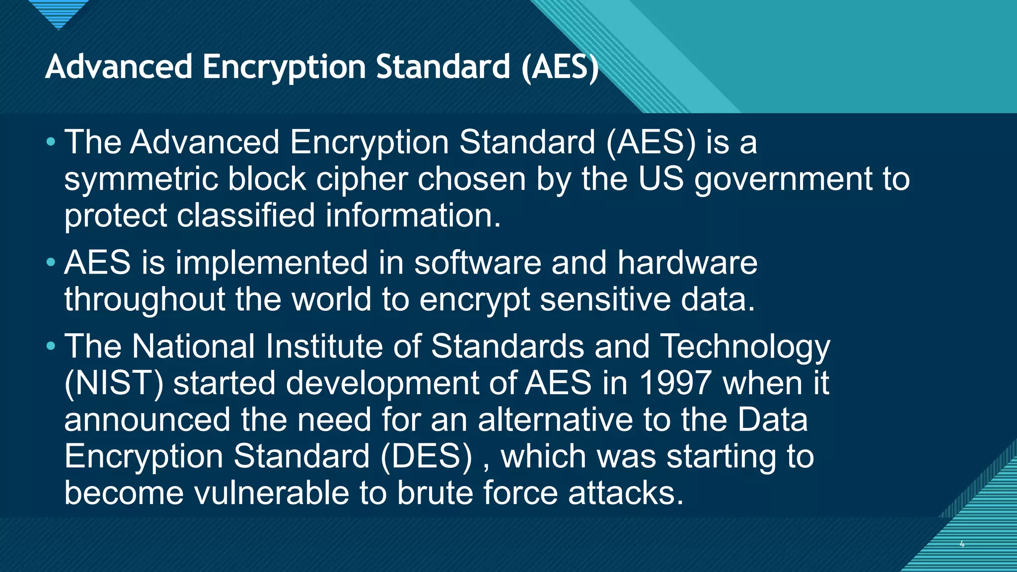
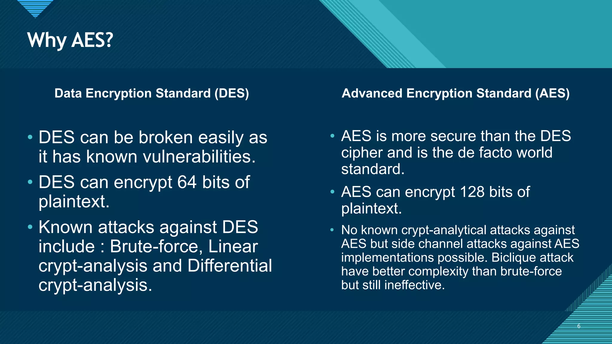
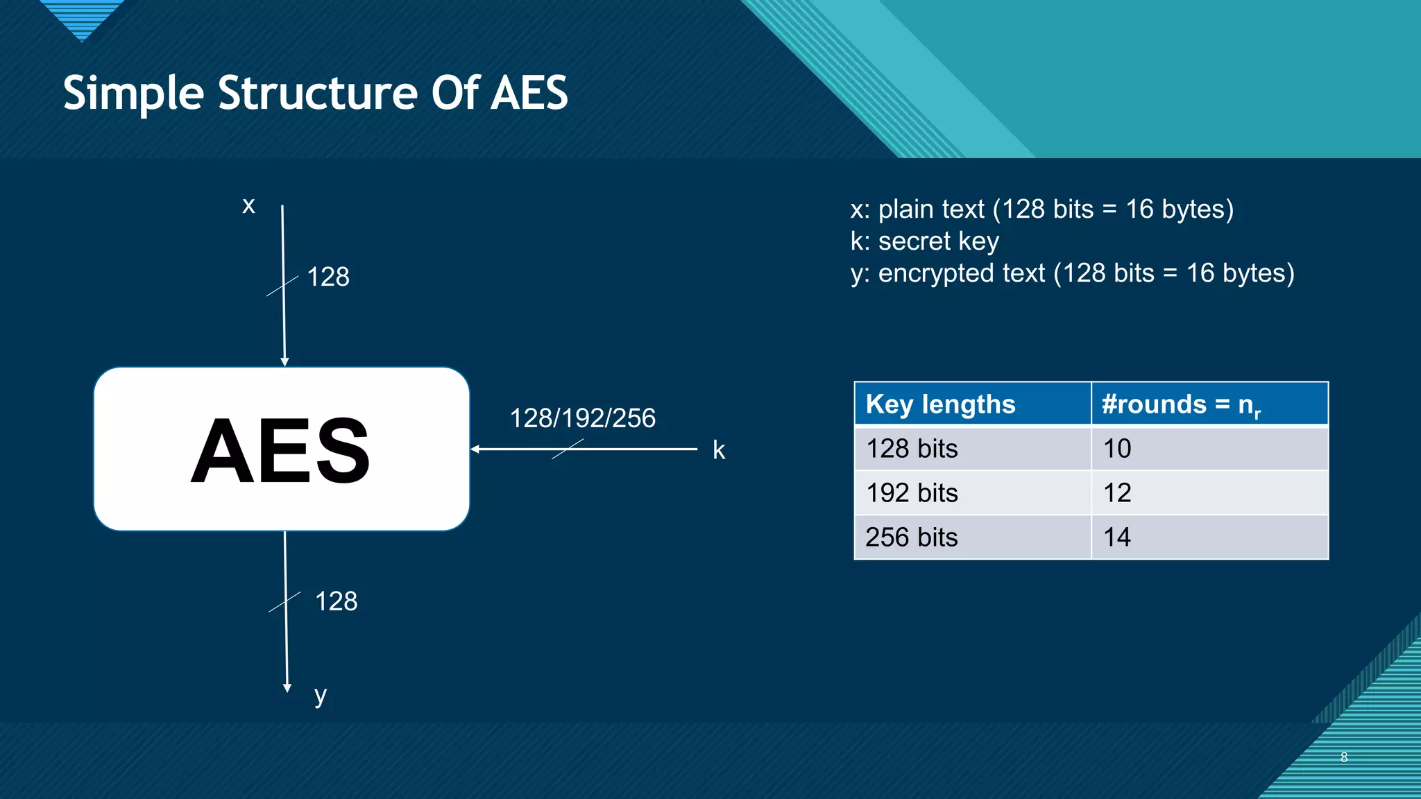
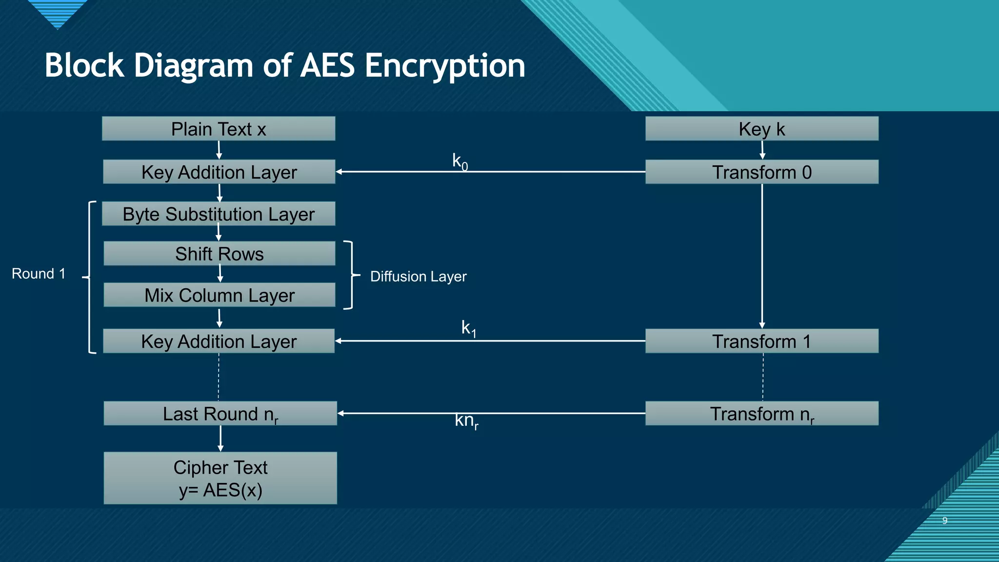
The document provides an overview of the Advanced Encryption Standard (AES) algorithm. It defines key terms like block, state, and XOR used in AES. It then describes the AES algorithm which works by repeating rounds that include byte substitution, shifting rows, mixing columns, and adding a round key. The number of rounds depends on the key size, being 10 for a 16-byte key and 14 for a 32-byte key. Encryption and decryption are similar processes performed in reverse order.
FPGA Implementation of an Area Optimized Architecture for 128 bit AES AlgorithmIJERA Editor
This paper aims at FPGA Implementation of an Area Optimized Architecture for 128 bit AES Algorithm. The
conventional designs use a separate module for 32 bit byte substitution and 128 bit byte substitution. The 32 bit
byte substitution is used in round key generation and the 128 bit byte substitution is used in the rounds. This
report presents a modified architecture of 128 bit byte substitution module using a single 32 bit byte substitution
module to reduce area.The AES encryption and decryption algorithm were designed using Verilog HDL. The
functionality of the modules were checked using ModelSim. The simulations were carried out in ModelSim and
Quartus II. The algorithm was implemented in FPGA and achieved a 2% reduction in the total logic element
utilization
Twofish is a symmetric block cipher that uses a 16-round Feistel network with a block size of 128 bits and key sizes up to 256 bits. It was one of the five finalists in the AES competition. Twofish's building blocks include S-boxes, MDS matrices, and a key schedule. Differential cryptanalysis is the most successful attack against Twofish but requires a large number of chosen plaintexts and computational resources beyond what is practical. Twofish has efficient performance across many platforms and competitive speeds compared to other AES finalists.
This document summarizes key aspects of the Data Encryption Standard (DES) block cipher. It describes how DES operates on 64-bit blocks using a 56-bit key in 16 rounds based on a Feistel network structure. Each round uses 48-bit subkeys generated from the main key. The document also discusses DES modes of operation like ECB, CBC, CFB, OFB and CTR and how they encrypt blocks of plaintext. Finally, it notes NIST's role in establishing encryption standards and the history of DES adoption as a standard in 1977.
Similar to Advanced encryption standard ug reseacrh (20)
Need for Speed: Removing speed bumps from your Symfony projects ⚡️Łukasz Chruściel
No one wants their application to drag like a car stuck in the slow lane! Yet it’s all too common to encounter bumpy, pothole-filled solutions that slow the speed of any application. Symfony apps are not an exception.
In this talk, I will take you for a spin around the performance racetrack. We’ll explore common pitfalls - those hidden potholes on your application that can cause unexpected slowdowns. Learn how to spot these performance bumps early, and more importantly, how to navigate around them to keep your application running at top speed.
We will focus in particular on tuning your engine at the application level, making the right adjustments to ensure that your system responds like a well-oiled, high-performance race car.
UI5con 2024 - Boost Your Development Experience with UI5 Tooling ExtensionsPeter Muessig
The UI5 tooling is the development and build tooling of UI5. It is built in a modular and extensible way so that it can be easily extended by your needs. This session will showcase various tooling extensions which can boost your development experience by far so that you can really work offline, transpile your code in your project to use even newer versions of EcmaScript (than 2022 which is supported right now by the UI5 tooling), consume any npm package of your choice in your project, using different kind of proxies, and even stitching UI5 projects during development together to mimic your target environment.
Enterprise Resource Planning System includes various modules that reduce any business's workload. Additionally, it organizes the workflows, which drives towards enhancing productivity. Here are a detailed explanation of the ERP modules. Going through the points will help you understand how the software is changing the work dynamics.
To know more details here: https://blogs.nyggs.com/nyggs/enterprise-resource-planning-erp-system-modules/
SOCRadar's Aviation Industry Q1 Incident Report is out now!
The aviation industry has always been a prime target for cybercriminals due to its critical infrastructure and high stakes. In the first quarter of 2024, the sector faced an alarming surge in cybersecurity threats, revealing its vulnerabilities and the relentless sophistication of cyber attackers.
SOCRadar’s Aviation Industry, Quarterly Incident Report, provides an in-depth analysis of these threats, detected and examined through our extensive monitoring of hacker forums, Telegram channels, and dark web platforms.
Software Engineering, Software Consulting, Tech Lead, Spring Boot, Spring Cloud, Spring Core, Spring JDBC, Spring Transaction, Spring MVC, OpenShift Cloud Platform, Kafka, REST, SOAP, LLD & HLD.
Introducing Crescat - Event Management Software for Venues, Festivals and Eve...Crescat
Crescat is industry-trusted event management software, built by event professionals for event professionals. Founded in 2017, we have three key products tailored for the live event industry.
Crescat Event for concert promoters and event agencies. Crescat Venue for music venues, conference centers, wedding venues, concert halls and more. And Crescat Festival for festivals, conferences and complex events.
With a wide range of popular features such as event scheduling, shift management, volunteer and crew coordination, artist booking and much more, Crescat is designed for customisation and ease-of-use.
Over 125,000 events have been planned in Crescat and with hundreds of customers of all shapes and sizes, from boutique event agencies through to international concert promoters, Crescat is rigged for success. What's more, we highly value feedback from our users and we are constantly improving our software with updates, new features and improvements.
If you plan events, run a venue or produce festivals and you're looking for ways to make your life easier, then we have a solution for you. Try our software for free or schedule a no-obligation demo with one of our product specialists today at crescat.io
Utilocate offers a comprehensive solution for locate ticket management by automating and streamlining the entire process. By integrating with Geospatial Information Systems (GIS), it provides accurate mapping and visualization of utility locations, enhancing decision-making and reducing the risk of errors. The system's advanced data analytics tools help identify trends, predict potential issues, and optimize resource allocation, making the locate ticket management process smarter and more efficient. Additionally, automated ticket management ensures consistency and reduces human error, while real-time notifications keep all relevant personnel informed and ready to respond promptly.
The system's ability to streamline workflows and automate ticket routing significantly reduces the time taken to process each ticket, making the process faster and more efficient. Mobile access allows field technicians to update ticket information on the go, ensuring that the latest information is always available and accelerating the locate process. Overall, Utilocate not only enhances the efficiency and accuracy of locate ticket management but also improves safety by minimizing the risk of utility damage through precise and timely locates.
GraphSummit Paris - The art of the possible with Graph TechnologyNeo4j
Sudhir Hasbe, Chief Product Officer, Neo4j
Join us as we explore breakthrough innovations enabled by interconnected data and AI. Discover firsthand how organizations use relationships in data to uncover contextual insights and solve our most pressing challenges – from optimizing supply chains, detecting fraud, and improving customer experiences to accelerating drug discoveries.
Transform Your Communication with Cloud-Based IVR SolutionsTheSMSPoint
Discover the power of Cloud-Based IVR Solutions to streamline communication processes. Embrace scalability and cost-efficiency while enhancing customer experiences with features like automated call routing and voice recognition. Accessible from anywhere, these solutions integrate seamlessly with existing systems, providing real-time analytics for continuous improvement. Revolutionize your communication strategy today with Cloud-Based IVR Solutions. Learn more at: https://thesmspoint.com/channel/cloud-telephony
Microservice Teams - How the cloud changes the way we workSven Peters
A lot of technical challenges and complexity come with building a cloud-native and distributed architecture. The way we develop backend software has fundamentally changed in the last ten years. Managing a microservices architecture demands a lot of us to ensure observability and operational resiliency. But did you also change the way you run your development teams?
Sven will talk about Atlassian’s journey from a monolith to a multi-tenanted architecture and how it affected the way the engineering teams work. You will learn how we shifted to service ownership, moved to more autonomous teams (and its challenges), and established platform and enablement teams.
Essentials of Automations: The Art of Triggers and Actions in FMESafe Software
In this second installment of our Essentials of Automations webinar series, we’ll explore the landscape of triggers and actions, guiding you through the nuances of authoring and adapting workspaces for seamless automations. Gain an understanding of the full spectrum of triggers and actions available in FME, empowering you to enhance your workspaces for efficient automation.
We’ll kick things off by showcasing the most commonly used event-based triggers, introducing you to various automation workflows like manual triggers, schedules, directory watchers, and more. Plus, see how these elements play out in real scenarios.
Whether you’re tweaking your current setup or building from the ground up, this session will arm you with the tools and insights needed to transform your FME usage into a powerhouse of productivity. Join us to discover effective strategies that simplify complex processes, enhancing your productivity and transforming your data management practices with FME. Let’s turn complexity into clarity and make your workspaces work wonders!
Why Mobile App Regression Testing is Critical for Sustained Success_ A Detail...kalichargn70th171
A dynamic process unfolds in the intricate realm of software development, dedicated to crafting and sustaining products that effortlessly address user needs. Amidst vital stages like market analysis and requirement assessments, the heart of software development lies in the meticulous creation and upkeep of source code. Code alterations are inherent, challenging code quality, particularly under stringent deadlines.
Neo4j - Product Vision and Knowledge Graphs - GraphSummit ParisNeo4j
Dr. Jesús Barrasa, Head of Solutions Architecture for EMEA, Neo4j
Découvrez les dernières innovations de Neo4j, et notamment les dernières intégrations cloud et les améliorations produits qui font de Neo4j un choix essentiel pour les développeurs qui créent des applications avec des données interconnectées et de l’IA générative.
Mobile App Development Company In Noida | Drona InfotechDrona Infotech
Looking for a reliable mobile app development company in Noida? Look no further than Drona Infotech. We specialize in creating customized apps for your business needs.
Visit Us For : https://www.dronainfotech.com/mobile-application-development/
Automated software refactoring with OpenRewrite and Generative AI.pptx.pdf
Advanced encryption standard ug reseacrh
1. Click to edit Master title style
1
Advanced
Encryption
Standard
B y,
A k a s h R a n j a n D a s
5 t h S e m e s t e r
B - Te c h , C o m p u t e r S c i e n c e A n d Te c h n o l o g y
S i d d a g a n g a I n s t i t u t e O f Te c h n o l o g y, Tu m k u r
2. Click to edit Master title style
2
Agenda
What is Advanced Encryption Standard (AES)?
Why AES?
Structure Of AES
o Basic Structure Of AES
o Detailed Structure Of AES
o Data Structure of AES
Working of AES encryption and Encryption
o AES Transformation Functions
o AES Key Expansion
Real World Software Application.
2
3. Click to edit Master title style
3
What is Advanced
Encryption Standard
(AES)?
3
4. Click to edit Master title style
4
Advanced Encryption Standard (AES)
4
• The Advanced Encryption Standard (AES) is a
symmetric block cipher chosen by the US government to
protect classified information.
• AES is implemented in software and hardware
throughout the world to encrypt sensitive data.
• The National Institute of Standards and Technology
(NIST) started development of AES in 1997 when it
announced the need for an alternative to the Data
Encryption Standard (DES) , which was starting to
become vulnerable to brute force attacks.
6. Click to edit Master title style
6
Why AES?
6
Data Encryption Standard (DES) Advanced Encryption Standard (AES)
• DES can be broken easily as
it has known vulnerabilities.
• DES can encrypt 64 bits of
plaintext.
• Known attacks against DES
include : Brute-force, Linear
crypt-analysis and Differential
crypt-analysis.
• AES is more secure than the DES
cipher and is the de facto world
standard.
• AES can encrypt 128 bits of
plaintext.
• No known crypt-analytical attacks against
AES but side channel attacks against AES
implementations possible. Biclique attack
have better complexity than brute-force
but still ineffective.
7. Click to edit Master title style
7
Structures Of AES
7
8. Click to edit Master title style
8
Simple Structure Of AES
8
AES
x
y
128
128
128/192/256
k
x: plain text (128 bits = 16 bytes)
k: secret key
y: encrypted text (128 bits = 16 bytes)
Key lengths #rounds = nr
128 bits 10
192 bits 12
256 bits 14
9. Click to edit Master title style
9
Block Diagram of AES Encryption
9
Plain Text x
Key Addition Layer
Byte Substitution Layer
Shift Rows
Mix Column Layer
Key Addition Layer
Round 1 Diffusion Layer
Transform 0
Key k
Transform 1
k0
k1
Last Round nr Transform nrknr
Cipher Text
y= AES(x)
10. Click to edit Master title style
10
Block Diagram of AES Decryption
10
Plain Text x = AES-1(y)
Key Addition Layer
Inverse Substitution Layer
Inverse Shift Rows
Inverse Mix Column Layer
Key Addition Layer
Round nr
Diffusion Layer
Transform 0
Key k
Transform 1
k0
k1
Round 1
Transform nr
knr
Cipher Text
Key Addition Layer
12. Click to edit Master title style
12
Working Of AES
12
13. Click to edit Master title style
13
AES Round Function for rounds 1, 2, …. nr-1
A0 A2 A2 A3 A4 A5 A6 A7 A8 A9 A10 A11 A12 A13 A14 A15
B0 B2 B2 B3 B4 B5 B6 B7 B8 B9 B10 B11 B12 B13 B14 B15
C0 C2 C2 C3 C4 C5 C6 C7 C8 C9 C10 C11 C12 C13 C14 C15
s s s s s s s s s s s s s s s s
k1
Byte Substitution
Shift Rows
Mix Columns
Key Addition
14. Click to edit Master title style
14
Byte Substitution Layer
14
• The first layer in each round.
• S(Ai) = Bi
• Ai : each byte in the state matrix.
• Bi : substituted byte.
• S : substitution function.
• S- Box is the only non-linear element of AES i.e. it holds that ByteSub(A) +
ByteSub(B) ≠ ByteSub(A+B) for two states A and B.
• S-Box substitution is bijective mapping.
• Each of 28 = 256 possible inputs elements is one-to-one mapped to one output element.
• Allows us to uniquely reverse the S-Box for decryption.
• S-Box is usually realized as a 256-by-8 bit look up table with fixed entries.
A0 A4 A8 A12
A1 A5 A9 A13
A2 A6 A10 A14
A3 A7 A11 A15
B0 B4 B8 B12
B1 B5 B9 B13
B2 B6 B10 B14
B3 B7 B11 B15
15. Click to edit Master title style
15
AES S – Box for Encryption
15
16. Click to edit Master title style
16
Inverse AES S – Box for Decryption
16
17. Click to edit Master title style
17
Computation of sub byte transformation
17
• Ex 1 : Let’s assume the input byte to the S-BOX is Ai = (C2)hex , then the substituted value is
S((C2)hex) = (25)hex
On a bit level:
S(11000010) = (00100101)
• Even though the S-Box is bijective, it does not have any fixed points i.e. there aren’t inputs values Ai
such that S(Ai) = Ai.
• Even the zero input is not a fixed point: S(00000000) = S(01100011)
• Ex 2 : Let’s assume that the input to the byte substitution layer is:
(C2,C2,C2,C2,….,C2)hex
The output state is then
(25,25,25,25,…..,25)hex
18. Click to edit Master title style
18
18
s0,0 s0,1 s0,2 s0,3
s1,0 s1,1 s1,2 s1,3
s2,0 s2,1 s2,2 s2,3
s3,0 s3,1 s3,2 s3,3
x
y
s'0,0 s'0,1 s'0,2 s'0,3
s'1,0 s'1,1 s'1,2 s'1,3
s'2,0 s'2,1 s'2,2 s'2,3
s'3,0 s'3,1 s'3,2 s'3,3
Input State matrix
S-Box
Output State matrix
19. Click to edit Master title style
19
Mathematical description of the S-BOX
19
GF(28)
inverse
Affine
mapping
Ai B’i Bi
• GF(28): Galois Field
• The function used here is Galois Field Inversion.
• B’i = Ai
-1, where Ai and B’i are considered elements in the galois field GF(28) with fixed
polynomial P(x) = x8+x4+x3+x+1.
• The inverse is obtained from a look up table of the multiplicative inverse in GF(28).
• In Affine mapping each byte B’i is multiplied by a constant bit-matrix followed by the
addition of a constant 8-bit vector.
20. Click to edit Master title style
20
Multiplicative inverse table in GF(28)
20
21. Click to edit Master title style
21
Affine Mapping
21
22. Click to edit Master title style
22
Example: S-BOX computation
22
• Ex: We assume the S-BOX input Ai = (11000010)2 = (C2)hex .
Solution:
Step 1: From look-up table (Multiplicative inverse table in GF(28)) we can see
that the inverse
Ai
-1 = B’i = (2F)hex = (00101111)2
Step 2 : We now apply the B’i bit vector as input to the affine transformation.
Bi = (00100101)2 = (25)hex
Thus, S((C2)hex) = (25)hex
• If one computes both steps for all 256 possible input elements of the S-BOX
and stores the results, one obtains the Multiplicative inverse table in GF(28).
23. Click to edit Master title style
23
Shift-Rows Sub Layer
23
• From Byte substitution layer we get the substituted byte matrix.
• Shift Rows transformation shifts:
• The second row of the state matrix by three bytes to the right.
• The third row by two bytes to the right.
• The fourth row by one byte to the right.
• The first row remains as it is.
• The purpose of the shift rows transformation is to increase diffusion properties of AES.
B0 B4 B8 B12
B1 B5 B9 B13
B2 B6 B10 B14
B3 B7 B11 B15
B0 B4 B8 B12
B5 B9 B13 B1
B10 B14 B2 B6
B15 B7 B3 B11
No shift
One position left shift
Two positions left shift
Three positions left shift
24. Click to edit Master title style
24
Mix-Column Sub Layer
24
• Linear Transformation which mixes each column of the state matrix.
• Let B be the 16 byte input state matrix and C be the 16 byte output state matrix,
Mix-Column(B) = C
• Each four byte column is considered as a vector and multiplied by a fixed 4x4 matrix.
25. Click to edit Master title style
25
Key Addition Layer
25
• The key schedule takes the original input key (of length 128,
192, or 256 bit) and derives the sub-keys used in AES.
• XOR addition of a sub-key is used both at the input and output of
AES. This process is referred to as key whitening.
• The number of sub-keys is equal to the number of rounds plus
one, due to the key needed for key whitening in the first key
addition layer.
• AES sub-keys are computed recursively, i.e. , in order to derive
sub-key ki , sub-key ki-1 must be known.
26. Click to edit Master title style
26
AES Key Schedule for 128-bit key size
26
27. Click to edit Master title style
27
Key Expansion Algorithm
27
keyExpansion(byte key[16], word[44]) {
word temp;
for(i = 0 ; i < 4 ; i++) {
w[i] = (key[4*i], key[4*i+1], key[4*i+2], key[4*i+3]);
}
for(i = 4 ; i < 44 ; i++) {
temp = w[i - 1];
if (i mod 4 == 0)
temp = subWord(rotWord(temp)) Rcon[i/4];
w[i] = w[i - 4] temp;
}
}
28. Click to edit Master title style
28
Real World Software
Application
28
29. Click to edit Master title style
29
End To End Encryption in Chat Systems
29
• WhatsApp has now became world’s leading chat portal for end to
end users and also for groups.
• The security system which it follows is End to End
Encryption(E2EE).
• E2EE uses AES (Cipher Block Chaining(CBC) Mode) and public
key cryptography to secure the chat between two users or
among the group members.
• In this AES plays an important role to encrypt the data.
• (User1->text)->encrypted text->decrypted text->(text->User2)