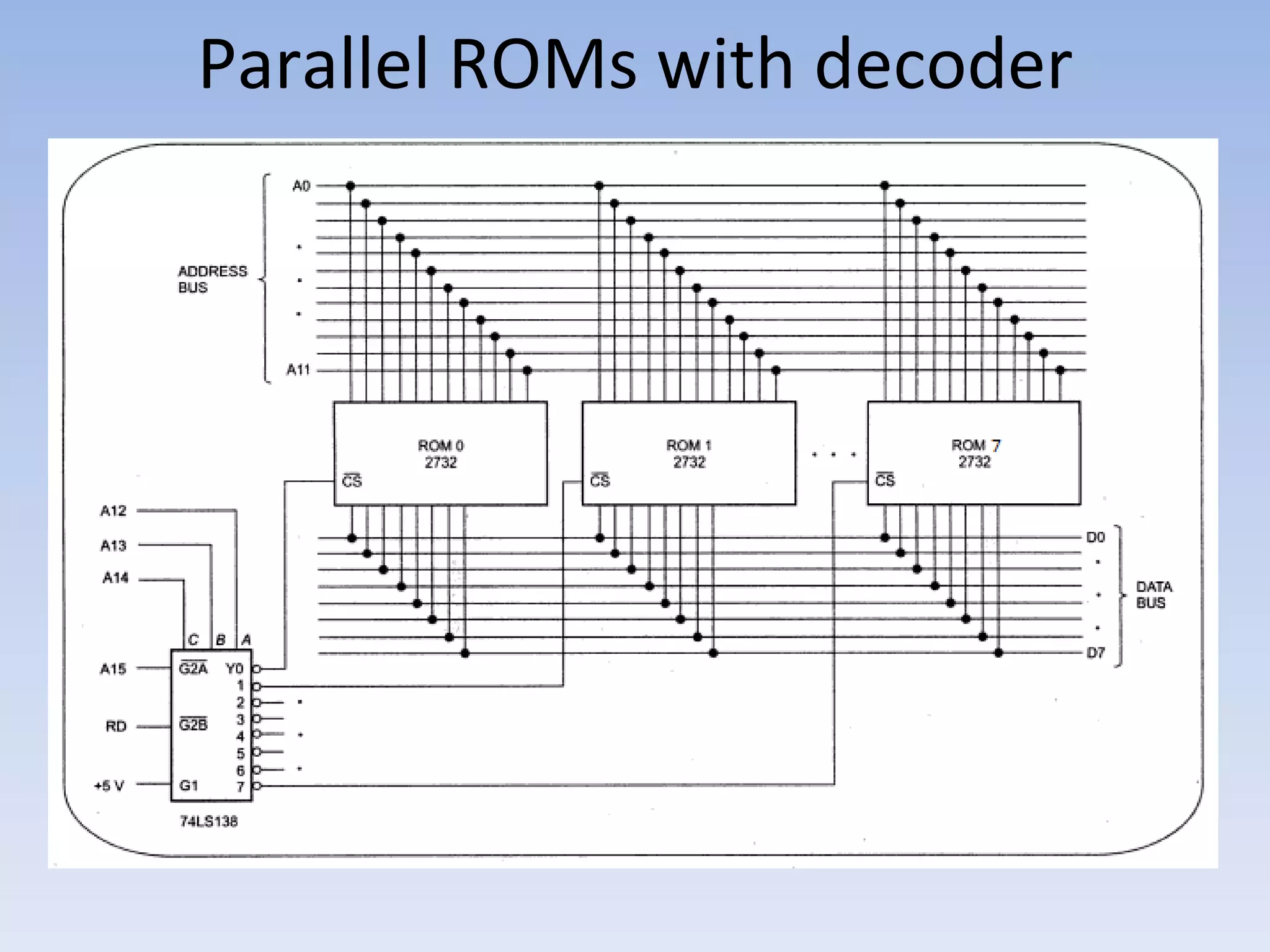
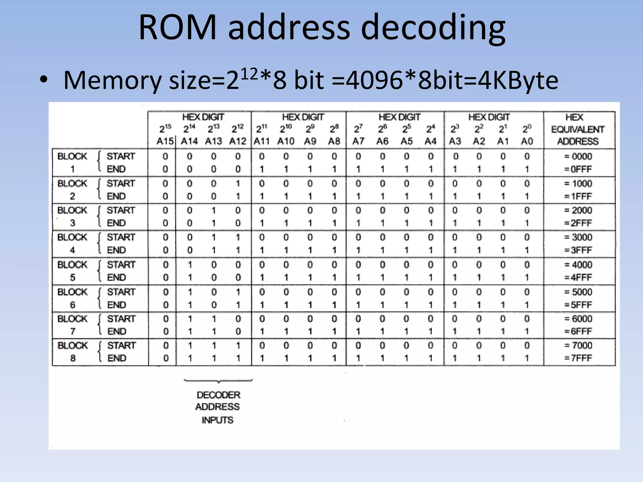
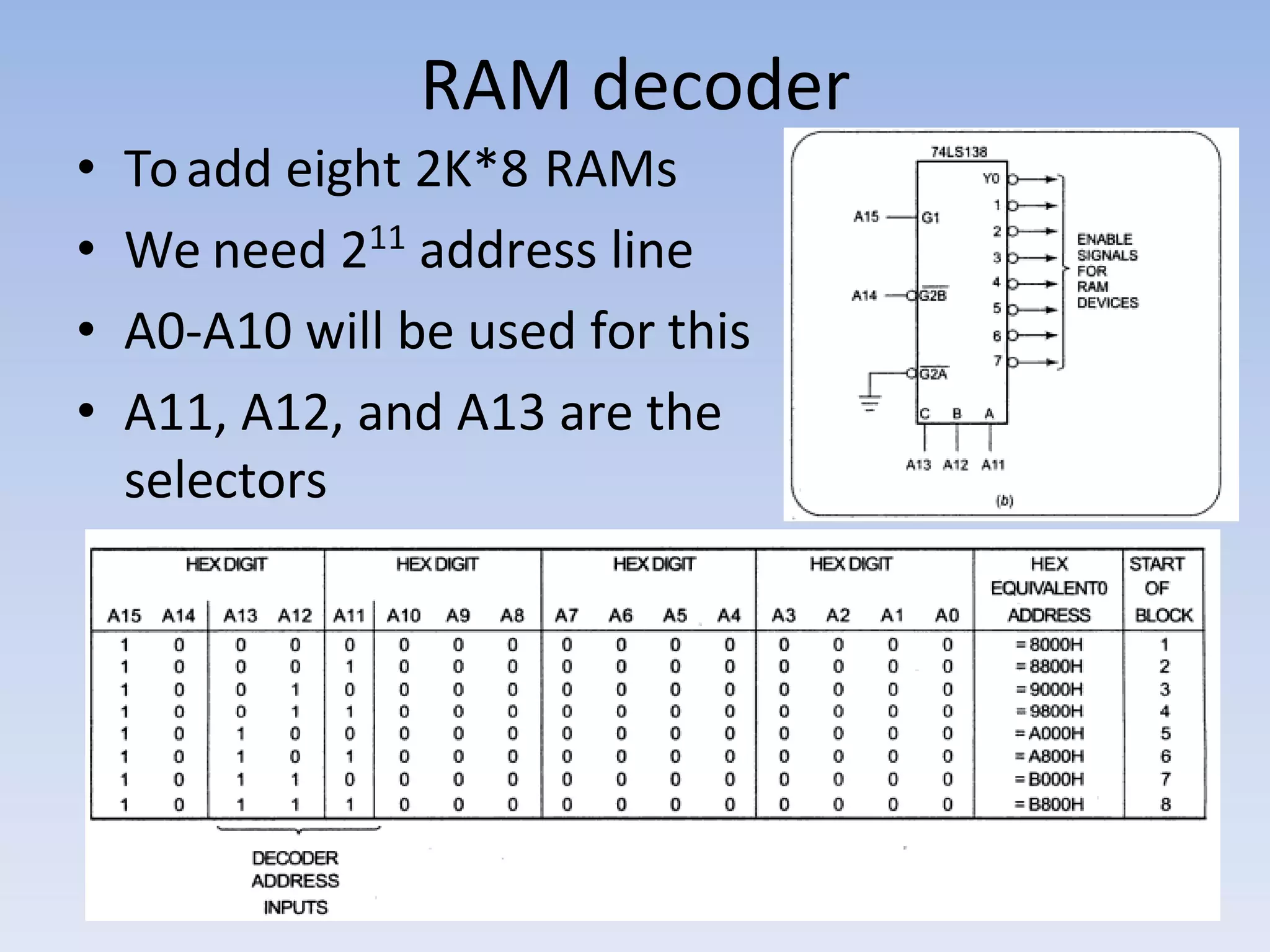
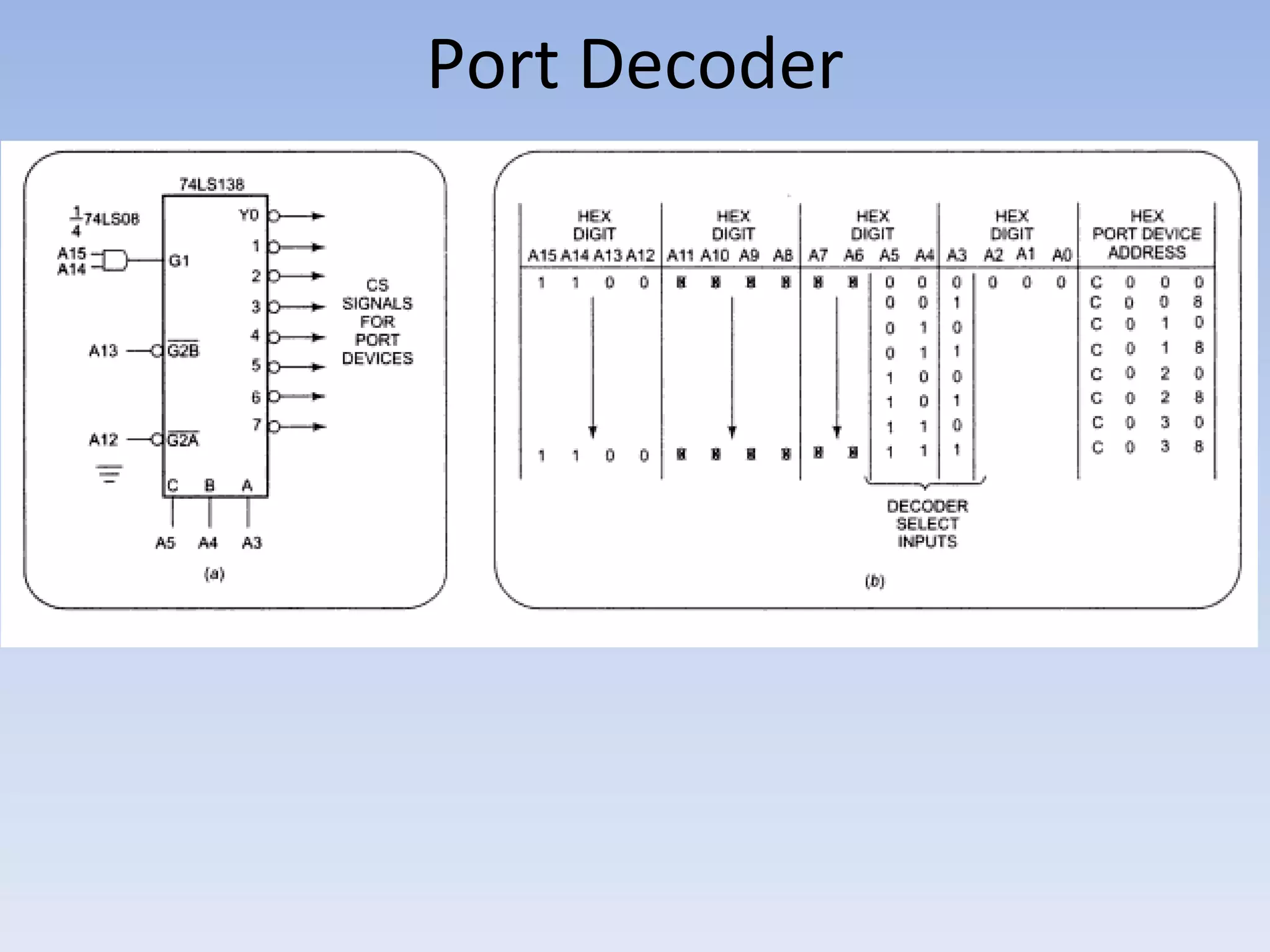
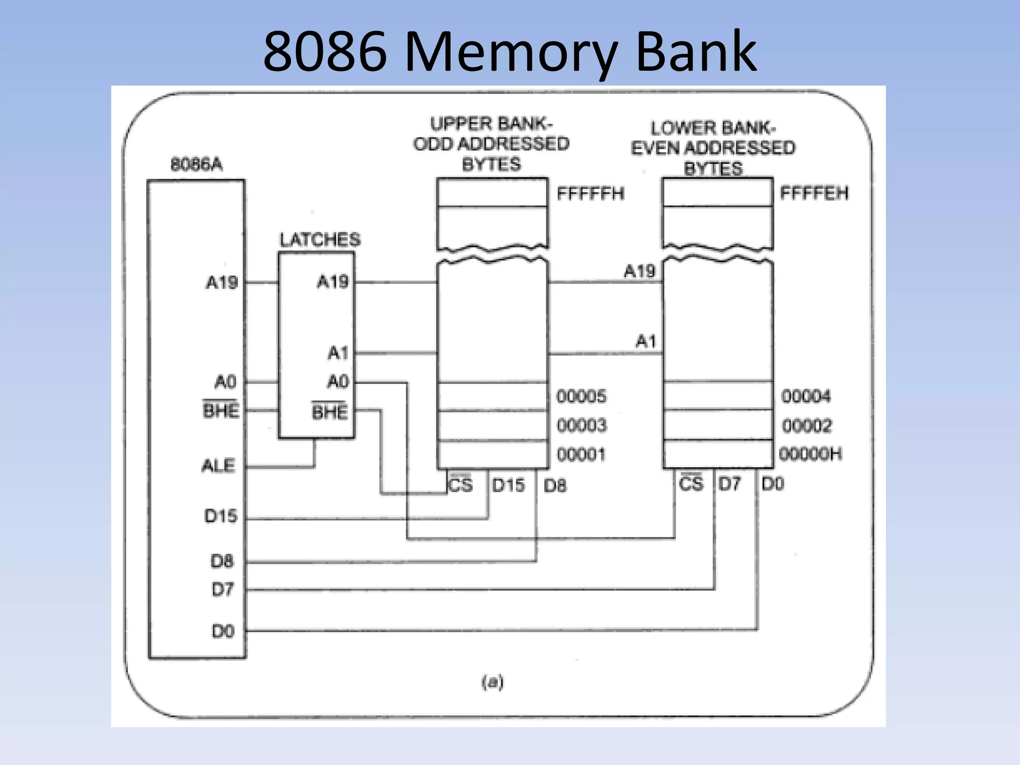
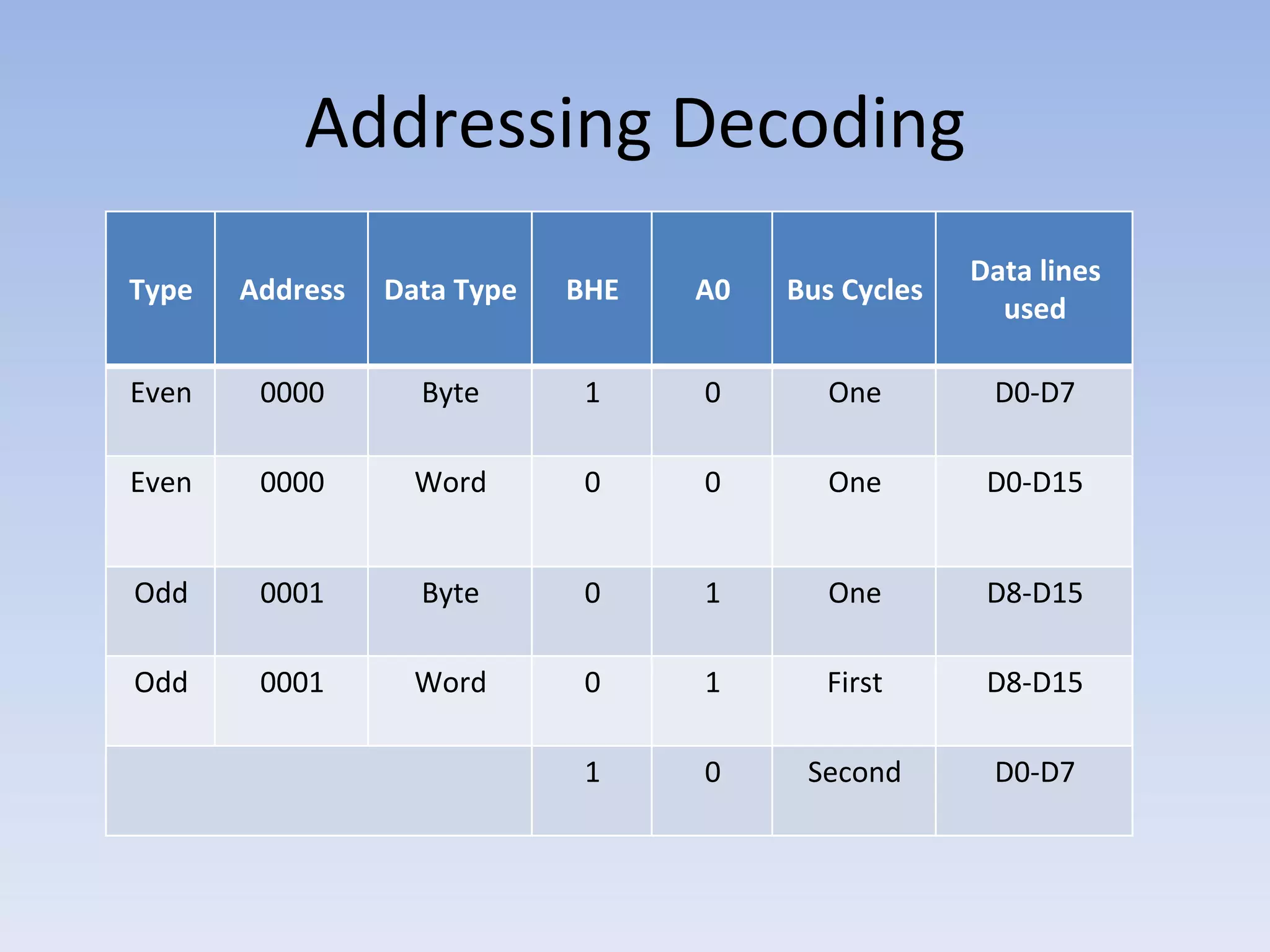
Addressing Memory and Ports
Reference: Microprocessors and
Interfacing – Douglas V Hall – Chapter 7
Address Decoder
• 3to8 decoders like 74LS138 serve as the
address decoders.
• Produces a signal which enables the ROM,
RAM, or port device, which is enabled for a
particular address
• Makes sure that only one device is enabled at
a time to put data in the bus.
Parallel ROMs with decoder
ROM address decoding
• Memory size=212
*8 bit =4096*8bit=4KByte
RAM decoder
• Toadd eight 2K*8 RAMs
• We need 211
address line
• A0-A10 will be used for this
• A11, A12, and A13 are the
selectors
Port Decoder
Memory Mapped I/O
• Using a decoder which translates memory
addressing to chip select signals for port
device is called Port Decoder
• Advantage: Any instruction that references
memory, can be used to input data from or
output data to ports
• Disadvantage: Some of the system memory
space is used up
8086 Memory Bank
Memory Bank
• Odd-even memory bank is used to read or
write 16 bit at a time
• Address A1-A19 are used to select desired
memory within the bank
• A0 is used for selecting lower bank and Bus
High Enable is used for selecting upper bank
• It also prevents unwanted writing of data in
adjacent memory location during byte
operation
Addressing Decoding
Type Address Data Type BHE A0 Bus Cycles
Data lines
used
Even 0000 Byte 1 0 One D0-D7
Even 0000 Word 0 0 One D0-D15
Odd 0001 Byte 0 1 One D8-D15
Odd 0001 Word 0 1 First D8-D15
1 0 Second D0-D7
Thanks…….

address decoding.pdf

  • 1.
    Addressing Memory andPorts Reference: Microprocessors and Interfacing – Douglas V Hall – Chapter 7
  • 2.
    Address Decoder • 3to8decoders like 74LS138 serve as the address decoders. • Produces a signal which enables the ROM, RAM, or port device, which is enabled for a particular address • Makes sure that only one device is enabled at a time to put data in the bus.
  • 3.
  • 4.
    ROM address decoding •Memory size=212 *8 bit =4096*8bit=4KByte
  • 5.
    RAM decoder • Toaddeight 2K*8 RAMs • We need 211 address line • A0-A10 will be used for this • A11, A12, and A13 are the selectors
  • 6.
  • 7.
    Memory Mapped I/O •Using a decoder which translates memory addressing to chip select signals for port device is called Port Decoder • Advantage: Any instruction that references memory, can be used to input data from or output data to ports • Disadvantage: Some of the system memory space is used up
  • 8.
  • 9.
    Memory Bank • Odd-evenmemory bank is used to read or write 16 bit at a time • Address A1-A19 are used to select desired memory within the bank • A0 is used for selecting lower bank and Bus High Enable is used for selecting upper bank • It also prevents unwanted writing of data in adjacent memory location during byte operation
  • 10.
    Addressing Decoding Type AddressData Type BHE A0 Bus Cycles Data lines used Even 0000 Byte 1 0 One D0-D7 Even 0000 Word 0 0 One D0-D15 Odd 0001 Byte 0 1 One D8-D15 Odd 0001 Word 0 1 First D8-D15 1 0 Second D0-D7
  • 11.