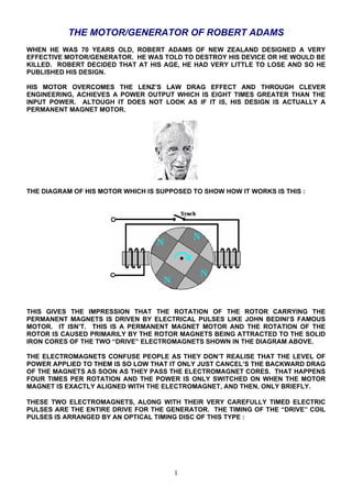
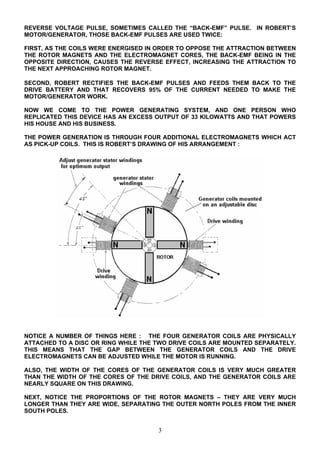
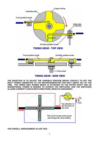
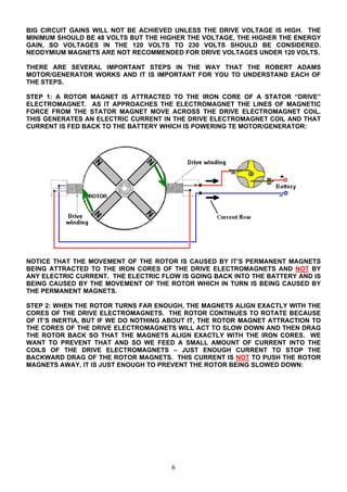
Robert Adams designed an efficient permanent magnet motor/generator. His design uses clever engineering to achieve an output power eight times greater than the input power. It works by using low power pulses to electromagnets to overcome magnetic drag effects and boost the rotation of the permanent magnet rotor. The rotation induces currents in pickup coils, and optimizing the timing of switching these coils on and off recaptures energy to power the device with very high efficiency. One replica produced 33 kilowatts of power from only 27.6 watts of input.
1) Charles Flynn developed a magnetic frame device that uses coils wound around an iron frame containing a powerful permanent magnet. Applying pulses to the coils can produce linear or circular motion without moving parts.
2) Lawrence Tseung created a similar magnetic frame device that inserts a permanent magnet into one arm. Applying sharp DC pulses to a coil on one side can produce over-unity output power from a coil on the other side if the pulses reinforce the magnet's field.
3) Thane Heins developed a figure-eight double toroid transformer that can produce over 30 times the input power. The unique magnetic flow paths allow most reverse magnetic flux to cancel out, greatly improving efficiency over standard transformers.
This document provides an overview of partial discharge training. It begins by defining what partial discharge is and discussing some of the common causes. It then explains how partial discharge is measured, including through transient earth voltage detection and ultrasonic detection. Various types of partial discharge are described, including internal discharges occurring within insulation cavities and surface discharges at insulation boundaries. Examples of partial discharge findings from switchgear components like cable terminations and circuit breakers are shown. The document also discusses partial discharge instrumentation and the analysis and reporting of partial discharge measurement results.
The document provides an overview of the Panacea-BOCAF On-Line University, which covers clean energy technology. It discusses the Tesla switch circuit, also known as the Brandt switch, which allows batteries to self-charge and power loads simultaneously. Several replications of the circuit are described, with the most successful being a mechanical version built by Matthew Jones that was able to free wheel a motor and charge batteries. Theories of how the circuit works are discussed, emphasizing the importance of abrupt switching and electron current blocking.
The document discusses lightning arresters, including their working principle, types, and advantages/disadvantages. Lightning arresters protect electrical equipment by diverting high voltage surges from lightning strikes or nearby objects to ground. They break down at a preset voltage to provide a path of least resistance to ground. Common types include rod gap, sphere gap, horn gap, and metal oxide arresters. Lightning arresters help reduce property damage and protect outdoor substation equipment and power lines from damage from lightning strikes. However, they require more space and have a higher installation cost than some alternatives.
The document provides details on the motor/generator designed by Robert Adams that is capable of exceeding 100% efficiency. It describes the basic operating principles and specific configurations that allow it to achieve high performance, including the use of power collection coils, magnet and electromagnet proportions, switching mechanisms, and construction methods. The motor utilizes pulsed electromagnets and permanent magnets on the rotor to generate power through clever timing of the electrical pulses and harvesting of back EMF effects.
This is a very old edition of the book. Download the latest revision here (permalink):
https://docs.google.com/file/d/0ByyeIdK8FssyLWJEQzlwTER2YTQ/edit?usp=sharing
A practical-guide-to-free energy-devices--patrick-j-kellyLex Pit
This document provides background information on a practical guide to free-energy devices. It discusses the author's interest in free-energy which began with a 1980s UK television program. It notes the lack of specific, practical information available on free-energy systems at the time. The author then wrote the first edition of this guide in 2005 to share what he had learned from his research in order to help others. The guide is intended as an introduction to the subject and covers various free-energy devices and inventors, but is not a complete resource. It aims to provide concise descriptions of devices and how they operate rather than extensive mathematical analysis.
its a brief report on Tesla coil. its help to learn
-How to work
-How to maintain the Tesla coil
- application and advantages
-Prove of Tesla mathematical equations.
SOLAR ENERGY TRACKER SYSTEM SEMINAR REPORTeeeraviriet
The document discusses renewable energy sources and focuses on solar photovoltaic energy. It states that solar PV capacity has grown rapidly in recent decades and is expected to become a major energy source in the future. However, solar PV still needs to be improved to maximize output, especially in areas with less sunlight. The project aims to develop a prototype solar tracking system to more efficiently orient panels toward the sun and increase solar PV performance.
This document describes a self-switching power supply project. It uses a voltage regulator, potentiometer, transistors, relay, and other components to provide a variable output voltage from 3.7V to 8.7V. It also automatically switches off when no load is connected, achieved using a transistor, diodes, capacitor, and relay circuit. The project was completed by three students for their Bachelor's degree in Electrical and Electronics Engineering at Teegla Krishna Reddy Engineering College.
This document summarizes a seminar presented by Priyanka Jain on wireless power transmission via solar power satellites. It provides an overview of the history of wireless power transmission dating back to Nikola Tesla's experiments in the late 1890s. It then discusses key concepts such as how solar power satellites would collect solar energy in space via photovoltaic cells and transmit it to rectennas on Earth via microwave beams to be converted back to electricity. While the technology faces challenges including potential health effects and interference issues, the document concludes that with further development and support, solar power satellites could become a viable new source of clean energy by harvesting the sun's power in space.
This PPT explains about the circuit breaker, and its types. Then about the need and purpose of the circuit breaker. And finally the testing and types of testing of circuit breakers.
This document describes various protection schemes for transformers, including differential, restricted earth fault, overcurrent, and thermal protection.
1) Differential protection compares currents entering and leaving the transformer zone to detect internal faults. It provides the best protection for internal faults.
2) Restricted earth fault protection is used to detect high-resistance winding-to-core faults not detectable by differential relays. It uses a neutral current transformer and is sensitive to internal earth faults.
3) Overcurrent protection uses relays with current coils to detect overloads and faults above a pickup threshold. It also includes ground-fault protection.
This document discusses underwater windmills, also known as tidal stream turbines, which harness the kinetic energy of moving underwater currents in a similar way that wind turbines use moving air. It provides background on the history and development of tidal stream turbines, including the first prototypes launched in the 1990s and 2000s in Scotland, England, and other locations. The document also describes the different types of underwater wind turbines, including horizontal axis and vertical axis designs, and discusses India's tidal energy potential, focused on locations in Gujarat and West Bengal. Initial tidal power project attempts and reports from the 1980s-2000s are also summarized.
Frank Prentice invented an "Electrical Power Accumulator" that produced 6 times the output power compared to the input power. It used a 500 watt input to a high frequency generator operating at 500,000 Hz to produce pulses along a transmission antenna wire supported above the ground. This tapped into "earth currents" to power a receiving antenna loop 18 feet away, which was able to light 50 sixty-watt light bulbs. Dave Lawton replicated Stan Meyer's water fuel cell circuit using a NE555 timer chip to generate square waves that pulsed a water splitter cell through a choke coil, tapping ambient energy.
High Voltage On-Site Testing with Partial Discharge Measurement (Cigre 502)AHMED MOHAMED HEGAB
During the life cycle of high voltage (HV) apparatus or systems many tests and measurements are performed to characterize the insulation condition. The results of these tests and
measurements should be compiled in a “life data record”, which supplies information on trends of diagnostic indicator values. The HV on-site test with partial discharge (PD) measurement has an intermediate position between routine tests and in-service monitoring measurements (on-line or offline)
This document discusses types of faults that can occur in electrical distribution systems and the importance of protection systems. It provides definitions for key terms like feeders, faults, and protection requirements. The summary describes the different types of protection schemes including unit and non-unit schemes. Unit schemes protect a specific area using principles like Kirchhoff's current law, while non-unit schemes have overlapping zones and use techniques like time-graded overcurrent protection to isolate faults.
Difference between grounding and earthingDr.Raja R
This document discusses the differences between grounding and earthing of electrical systems. Grounding refers to connecting the current-carrying parts of a system to ground and provides a return path for leakage currents. Earthing connects the non-current carrying metal parts of equipment to ground to prevent electric shocks by discharging any leakage currents. The key differences are explained through definitions, diagrams, and specifications for proper grounding rods and earthing electrodes.
This document contains 23 questions and answers related to electrical engineering. It covers topics like capacitors, circuit breakers, transformers, power factor, earthing, different types of circuit breakers and their uses. The questions range from basic concepts to more advanced topics on transformers, protection devices, earthing systems and motor operations.
This document discusses the double cage induction motor. It aims to achieve high starting torque without affecting efficiency. This is done by using a rotor with two cages made of different materials - an outer cage of high resistivity material and an inner cage of low resistance material like copper. At start up, most current flows through the high resistance outer cage, providing high starting torque. During normal operation, current mostly flows through the low resistance inner cage, maintaining high efficiency. Some key applications mentioned are water pumps and machines like lathes and drills that require high starting torque.
The document discusses different types of circuit breakers, including air blast, vacuum, oil, and SF6 circuit breakers. It explains that a circuit breaker can make, carry, and break currents under normal and abnormal circuit conditions. The operating mechanism involves using stored energy to move a moving contact to open or close the circuit. When contacts separate during a fault, an arc is formed that must be quickly quenched for circuit interruption. Each breaker type uses a different medium, such as air, vacuum, oil or SF6 gas, to rapidly cool and extinguish the arc. Modern systems commonly use vacuum or SF6 breakers for their fast, reliable performance.
Circuit BreakersA circuit breaker is an automatically operated electrical switch designed to protect an electrical circuit from damage caused by excess current from an overload or short circuit. Its basic function is to interrupt current flow after a fault is detected.
Wide area monitoring systems (WAMS) are essentially based on the new data acquisition technology of phasor measurement and allow monitoring transmission system conditions over large areas in view of detecting and further counteracting grid instabilities.
This document describes the design of a solar tracking system using an 8051 microcontroller that automatically orients a solar panel to track the sun from east to west for maximum solar energy collection. The system uses a light dependent resistor to sense light intensity and signal a stepper motor controlled by the microcontroller to rotate the panel. It provides an affordable way to maximize solar panel efficiency through software algorithms that precisely position the panel without needing many sensors.
Vacuum circuit breakers use vacuum to extinguish the arc when opening contacts. They have fixed contacts, moving contacts, and an arc shield mounted inside a vacuum chamber. When a fault is detected, the contacts separate and the arc is quickly extinguished in the vacuum. This allows vacuum circuit breakers to reliably interrupt high fault currents. They have advantages over other circuit breakers like being compact, reliable, and able to interrupt heavy fault currents without fire hazards.
This document provides information on pulsed energy devices described by Patrick J. Kelly, specifically focusing on the motor/generator designed by Robert Adams. The summary is:
1) Robert Adams designed an electric motor that uses permanent magnets on the rotor and pulsed electromagnets on the stator. When configured correctly, the output power exceeds the input power by a large margin, such as 800%.
2) The device operates by using power collection coils positioned and timed to contribute back EMF to drive the rotor. Additional electromagnets are pulsed on and off to further boost efficiency beyond 100%.
3) Practical details are provided on components like magnet shape and size, coil dimensions, switching methods and
alternators its types and its functions….What you've just experienced is an example of an alternator breathing its last breath.
Your first thought might have been the battery is dying. In a sense, you would be right because the battery and the alternator are related, but the battery tends to get all the press.
This presentation aims to explain the mechanics of alternators, how you can diagnose problems and what you can do if you have a bad alternator.
You will come to now to some background information about alternators and the war of the currents.
The document provides an acknowledgement and thanks for those who supported the completion of a physics project. It thanks God, the principal, physics teacher, parents, and classmates for their guidance and support. The acknowledgement indicates the project was completed successfully with their help.
This document discusses how generators work and generator testing procedures. It explains that a generator uses electromagnetic induction to convert mechanical energy from a drive belt into electrical current. It also summarizes the key components of a generator, including the rotor, stator, diodes, and voltage regulator. Proper testing and maintenance are required to diagnose generator issues.
This document discusses how generators work and procedures for testing generators. It explains that a generator uses electromagnetic induction to convert mechanical energy from a drive belt into electrical current. It also describes how to disassemble a generator and test its components such as the rotor, stator, diodes, and wiring. Proper generator testing ensures the charging system keeps the battery fully charged.
working principle of alternators and its kind _What you've just experienced is an example of an alternator breathing its last breath.
Your first thought might have been the battery is dying. In a sense, you would be right because the battery and the alternator are related, but the battery tends to get all the press.
This presentation aims to explain the mechanics of alternators, how you can diagnose problems and what you can do if you have a bad alternator.
You will come to now to some background information about alternators and the war of the currents.
We have designed a Wind Generator as our final year Engineering project. For information please go through the presentation or else you can contact me. Feel free to give your valued suggestions
This document provides an overview of AC generators and their components. It discusses the basic principles of magnetic induction that AC generators rely on to produce power. It describes different types of AC generators like rotating armature and rotating field alternators. It also discusses the components of AC generators like the rotor, stator, field, and armature. Additionally, it covers practical AC generator concepts like prime movers, excitation, single and polyphase outputs, voltage control, and parallel operation of multiple generators. The document is intended to introduce the basic concepts and components of AC generators at an elementary level.
This document discusses types of AC motors including induction motors with squirrel cage and slip ring rotors, and synchronous motors. It covers the basics of AC motor operation such as three phase electricity, electromagnetic induction, rotating magnetic fields, Lorentz force, and synchronous speed. It provides details on induction motor components like the stator and different rotor types. It also explains induction motor working principles, speed-torque characteristics in motoring, generating and braking modes, and applications of universal motors.
This presentation discusses brushless DC motors. It explains that brushless DC motors do not have brushes, instead using electronics for commutation. This makes them highly efficient over a wide speed range with smooth operation and holding torque when stationary. The presentation describes the basic working principles of brushless DC motors, including their rotor, stator, and electronic control of electromagnets. It discusses how brushless DC motors eliminate the need for commutators through electronic position sensing and switching. Examples of applications are provided, along with advantages like increased efficiency and high performance. Disadvantages include higher cost compared to brushed DC motors and limited high power capabilities.
This document provides information about basic AC electrical generators. It discusses different types of generators including rotating armature generators, rotating field generators, and polyphase generators. It also covers topics like air cooled generators, temperature rise, reliability, construction details, stator and rotor design for both air cooled and hydrogen/water cooled generators. The document includes sections on generator isolation, seal oil systems, stator cooling water systems, and excitation systems. It concludes with sample review questions and a final examination.
This document provides information about basic AC electrical generators. It discusses different types of generators including rotating armature generators and rotating field generators. It also covers polyphase generators and the advantages of three-phase power systems. The document describes different cooling methods for generators including air cooling, hydrogen cooling, and water cooling. It discusses factors that influence generator design such as temperature rise, reliability, and construction considerations. The construction section provides details about generator stators, windings, rotors, cooling systems, and excitation systems.
This document provides an overview of speed controllers for DC motors. It discusses the basic principles of open and closed loop speed control using pulse width modulation (PWM) to vary the average voltage sent to the motor. Key aspects covered include:
- Using PWM switching of the motor voltage at frequencies above audibility to vary perceived average speed.
- Choosing PWM frequencies based on motor characteristics to minimize current ripple.
- Circuit designs for basic speed control, regeneration, and reversing motor direction using an H-bridge.
- Generating PWM signals using analog electronics like a triangle-wave oscillator comparator.
1. The document discusses the principle of operation of 3-phase induction motors and their applications. It explains how a rotating magnetic field is generated using a 3-phase supply, which causes the rotor to turn.
2. Key aspects covered include induction motor construction, torque-speed characteristics, multi-pole motors, and applications of variable frequency drives.
3. The document compares DC and AC machines, and explains why AC induction motors are more commonly used due to the availability of single or multi-phase AC power.
The document discusses the principles of operation of 3-phase induction motors. It explains that a 3-phase induction motor operates using a rotating magnetic field produced by a 3-phase AC current in the stator windings which causes the rotor to turn. As the rotor turns slightly slower than the rotating field, a slip is produced which generates an induced current in the rotor and produces torque. The torque causes the rotor to accelerate until the motor reaches its operating speed where the torque equals the load.
This document discusses the principle of operation of 3-phase induction motors. It explains that a 3-phase induction motor operates using a rotating magnetic field produced by a 3-phase AC current in the stator windings which causes the rotor to turn. As the rotor turns slightly slower than the rotating magnetic field, a slip is produced which induces currents in the rotor windings to generate torque. The torque causes the rotor to accelerate until the motor reaches its operating speed where the torque exactly balances the mechanical load on the shaft.
The document discusses the principles of operation of 3-phase induction motors. It explains that a 3-phase induction motor operates using a rotating magnetic field produced by a 3-phase AC current in the stator windings which causes the rotor to turn. The speed of the rotor is slightly less than the synchronous speed of the rotating magnetic field due to slip. The difference between the rotor speed and synchronous speed is used to produce torque. Torque-speed characteristics and power output equations for 3-phase induction motors are also presented.
POWER FACTOR CORRECTION OF A 3-PHASE 4- SWITCH INVERTER FED BLDC MOTORvanmukil
This document provides an overview of brushless DC motors. It discusses their construction, operation, and applications. Key points include:
- BLDC motors have electronic commutation rather than mechanical brushes. They provide linear torque-speed characteristics like brushed DC motors.
- They consist of a radially magnetized permanent magnet rotor and phase windings on the stator. Electronic controllers and position sensors enable synchronized commutation.
- BLDC motors are widely used in applications like computers, appliances, electric vehicles due to their reliability, efficiency and power density compared to brushed DC motors.
- The document reviews BLDC motor components, control methods, torque production principles and common configurations like three-phase
The document discusses the asynchronous or induction motor, specifically focusing on its construction and working principles. It describes the main components of an asynchronous motor including the stator and rotor, and explains how different types of rotors like squirrel cage and slip ring function through electromagnetic induction to generate torque without a direct electrical connection. The working principle is demonstrated through diagrams showing how a rotating magnetic field is produced in the stator to induce currents in the rotor and make it rotate at a slightly lower synchronous speed.
- A bifilar coil contains two closely spaced, parallel windings that can be used to either magnify or neutralize magnetic fields. When the currents flow in the same direction, the magnetic fields add up, but when they flow in opposite directions the fields cancel out.
- Bifilar coils are used in some relay and transformer applications to suppress back-emf by intercepting magnetic energy through an isolated secondary coil. However, this increases switching time.
- Bifilar coils impose inductance in common mode but not differential mode, making them useful for eliminating common mode signals in electronic circuits like Ethernet cables.
Gauss's law relates the electric flux through a closed surface to the electric charge enclosed. The direction of the magnetic field lines in electromagnets spreads out from the magnet, becoming weaker. Magnetic flux through a closed surface is always zero.
This document provides a chart showing the current required to raise the temperatures of insulated conductors of different diameters in free air. It then discusses several key factors that influence the current carrying capacity of conductors, including conductor size, ambient temperature, number of conductors, and installation method. The document cautions that no simple chart can determine current ratings for all systems given the various factors involved.
This document provides instructions for building an impulse generator that extracts useful energy from gravity. It summarizes William Skinner's gravity-powered device from 1939 that uses falling weights in a circular motion without the weights reaching the ground. It then describes the design of an impulse generator being built, which uses one large flywheel driven by one or two smaller flywheels through intermittent contact to gain energy from acceleration and inertia. Detailed steps are provided for constructing the flywheels and support structure from steel, including cutting, welding, and fastening bearings to allow rotation.
1) The document describes a method for avoiding Lenz's Law by using an asymmetrical arrangement of coils and permanent magnets. This allows power to be extracted from the output coil without affecting the input coil.
2) The key principle is that orthogonal coils do not normally interact, but adding permanent magnets between the coils breaks the symmetry and allows the magnetic field from one coil to induce current in the other coil.
3) The output power depends on factors like the intensity of the magnetic field from the magnets and the speed and distance of movement of this magnetic field caused by the current in the input coil. Replacing the permanent magnets with electromagnets is also proposed.
This document provides instructions for building a simple free-energy generator. It describes replicating an existing rotary generator design with a rotor that has magnets and a stationary part called the stator with electromagnetic coils. The original design achieved 330% efficiency. The document suggests modifications to improve performance, such as adding an adjustable timing coil to control pulse timing for better output. Safety precautions are also outlined when handling strong magnets.
This document discusses fuel-less engines that draw energy from the environment rather than burning fuel. It provides examples of how sailing boats, hydroelectric power, and windmills get their power from the sun without directly burning a fuel. It then describes several engine designs that operate using compressed air, including ones from Bob Neal, Scott Robertson, and Leroy Rogers. These engines recharge the compressed air supply using heat from the surrounding air and without directly burning a fuel.
1) Lawrence Tseung's theory of "Lead-out" energy suggests that excess energy can be obtained from pulsing or vibrating gravitational systems like flywheels.
2) Chas Campbell demonstrated a flywheel system that produced excess electrical power output compared to the motor input. This was due to jerky drive belts causing rapid pulses that extracted energy from the gravitational field, enhanced by the large flywheel mass and diameter.
3) Multiple heavy discs in the system, even if not intended as flywheels, contributed to the free energy gain through the effects of their rotation described in Tseung's theory and the "rule of shoulder of Archimedes".
The document discusses the Tarbela Power Station in Pakistan. It contains 14 questions and answers about the power station. Some key details:
- There are 14 units at the Tarbela Power Station that can generate a total of 3478MW of electricity. Units 1-10 are 175MW each, while units 11-14 are 432MW each.
- The station uses "Frances turbines". The diameter of the penstock is 24.5 inches and the Main Inlet Valve is 48.5 inches.
- The penstock pressure is 150 bar. The pressure of the cooling water system is 10 bar. The lubrication oil system has a maximum pressure of 400 Psi.
-
Identification of fuel pipe and steam pipe(Thermal Power plant Muzafarghar )HaseebAhmadChughtai
This document provides an overview of the Thermal Power Station located in Muzaffargarh, Pakistan. It has two phases, with Phase 1 having 3 Russian units of 210 MW each and 1 Chinese unit of 320 MW. Phase 2 has 2 Chinese units of 200 MW each. The power station uses steam to power turbines that generate electricity. It has a total installed capacity of 1350 MW. Water tube boilers are used, with dual fuel combustion systems for gas and furnace oil. The power station feeds into the national grid system and is an important source of electricity generation in Pakistan.
This document outlines a project to digitize the fuel injection pump test bench. It discusses the motivation to work with industry and benefit the country. The objectives are to create a more accurate and efficient digital test bench. Currently, the manual test bench has issues like human error and inefficiency. The solution is to add sensors like microwave, ultrasonic, and laser sensors to digitize the measurements and automate the process. This will enhance accuracy and help solve problems for automobile industries. The project will be completed by April 2018 by the team members who will each contribute to different tasks like report writing, data collection, and visits. In conclusion, the digitized test bench will improve accuracy, help the country's defense sector, and benefit society
Principle of comunication rfid based attandance and secu...HaseebAhmadChughtai
This document is a project proposal for an RFID-based attendance and security system. It outlines the objectives to create an algorithm for taking attendance using RFID and to secure the system. The system will use an Arduino, RFID sensor, servo motor, buzzer, and LCD display. A student or employee will scan their RFID card at the door, which will open if their card is registered with the system and mark their attendance on the LCD display. The goal is to automate the attendance process for large classes and provide security access for a school or office.
This document discusses the design of flywheels. It begins by introducing flywheels as inertial energy storage devices that absorb mechanical energy and serve as reservoirs, storing energy when supply exceeds demand and releasing it when demand exceeds supply. It then discusses two stages of flywheel design: determining the required energy and inertia, and defining the geometry. The document provides equations for determining inertia based on required energy change and speed fluctuation coefficient. It also discusses stresses in flywheels due to centrifugal force and modern high-speed composite flywheel designs. Applications mentioned include smoothing speed fluctuations in engines and powering electric vehicles.
Kalabagh is a town in Mianwali District, Punjab known for its scenic views of the Indus River and hills. It is the proposed site of the Kalabagh Dam, a multi-purpose project that would generate hydropower, provide water storage, and irrigation. The dam has faced opposition from Sindh, KPK, and Balochistan over concerns about water sharing and risks of flooding and waterlogging. Supporters argue the dam is needed to address Pakistan's energy and irrigation needs. While it has economic benefits, relocating residents and impacts on the environment are disadvantages that must be addressed.
Identification of fuel pipe and steam pipe(thermal power plant Muzafargha)HaseebAhmadChughtai
This document provides an overview of the Thermal Power Station located in Muzaffargarh, Pakistan. It has two phases, with Phase 1 having 3 Russian units of 210 MW each and 1 Chinese unit of 320 MW. Phase 2 has 2 Chinese units of 200 MW each. The power station uses steam to power turbines that generate electricity. It uses furnace oil and gas as fuel. The document discusses the different units and their capacities, as well as providing background information on thermal power stations and the steam turbine process.
This document describes projects created by a group of students using Arduino including an elevator system, automatic door, and RC car.
The elevator system uses an Arduino, relay, AC to DC converter, and DC motor to control the speed and movement of an elevator. An RFID card scanner was also created using an Arduino, RFID sensor, servo motor, and buzzer to control a door. Additionally, an RC car was built using an Arduino, L293D motor driver IC, and DC motors.
CHINA’S GEO-ECONOMIC OUTREACH IN CENTRAL ASIAN COUNTRIES AND FUTURE PROSPECTjpsjournal1
The rivalry between prominent international actors for dominance over Central Asia's hydrocarbon
reserves and the ancient silk trade route, along with China's diplomatic endeavours in the area, has been
referred to as the "New Great Game." This research centres on the power struggle, considering
geopolitical, geostrategic, and geoeconomic variables. Topics including trade, political hegemony, oil
politics, and conventional and nontraditional security are all explored and explained by the researcher.
Using Mackinder's Heartland, Spykman Rimland, and Hegemonic Stability theories, examines China's role
in Central Asia. This study adheres to the empirical epistemological method and has taken care of
objectivity. This study analyze primary and secondary research documents critically to elaborate role of
china’s geo economic outreach in central Asian countries and its future prospect. China is thriving in trade,
pipeline politics, and winning states, according to this study, thanks to important instruments like the
Shanghai Cooperation Organisation and the Belt and Road Economic Initiative. According to this study,
China is seeing significant success in commerce, pipeline politics, and gaining influence on other
governments. This success may be attributed to the effective utilisation of key tools such as the Shanghai
Cooperation Organisation and the Belt and Road Economic Initiative.
6th International Conference on Machine Learning & Applications (CMLA 2024)ClaraZara1
6th International Conference on Machine Learning & Applications (CMLA 2024) will provide an excellent international forum for sharing knowledge and results in theory, methodology and applications of on Machine Learning & Applications.
Introduction- e - waste – definition - sources of e-waste– hazardous substances in e-waste - effects of e-waste on environment and human health- need for e-waste management– e-waste handling rules - waste minimization techniques for managing e-waste – recycling of e-waste - disposal treatment methods of e- waste – mechanism of extraction of precious metal from leaching solution-global Scenario of E-waste – E-waste in India- case studies.
Harnessing WebAssembly for Real-time Stateless Streaming PipelinesChristina Lin
Traditionally, dealing with real-time data pipelines has involved significant overhead, even for straightforward tasks like data transformation or masking. However, in this talk, we’ll venture into the dynamic realm of WebAssembly (WASM) and discover how it can revolutionize the creation of stateless streaming pipelines within a Kafka (Redpanda) broker. These pipelines are adept at managing low-latency, high-data-volume scenarios.
Understanding Inductive Bias in Machine LearningSUTEJAS
This presentation explores the concept of inductive bias in machine learning. It explains how algorithms come with built-in assumptions and preferences that guide the learning process. You'll learn about the different types of inductive bias and how they can impact the performance and generalizability of machine learning models.
The presentation also covers the positive and negative aspects of inductive bias, along with strategies for mitigating potential drawbacks. We'll explore examples of how bias manifests in algorithms like neural networks and decision trees.
By understanding inductive bias, you can gain valuable insights into how machine learning models work and make informed decisions when building and deploying them.
DEEP LEARNING FOR SMART GRID INTRUSION DETECTION: A HYBRID CNN-LSTM-BASED MODELgerogepatton
As digital technology becomes more deeply embedded in power systems, protecting the communication
networks of Smart Grids (SG) has emerged as a critical concern. Distributed Network Protocol 3 (DNP3)
represents a multi-tiered application layer protocol extensively utilized in Supervisory Control and Data
Acquisition (SCADA)-based smart grids to facilitate real-time data gathering and control functionalities.
Robust Intrusion Detection Systems (IDS) are necessary for early threat detection and mitigation because
of the interconnection of these networks, which makes them vulnerable to a variety of cyberattacks. To
solve this issue, this paper develops a hybrid Deep Learning (DL) model specifically designed for intrusion
detection in smart grids. The proposed approach is a combination of the Convolutional Neural Network
(CNN) and the Long-Short-Term Memory algorithms (LSTM). We employed a recent intrusion detection
dataset (DNP3), which focuses on unauthorized commands and Denial of Service (DoS) cyberattacks, to
train and test our model. The results of our experiments show that our CNN-LSTM method is much better
at finding smart grid intrusions than other deep learning algorithms used for classification. In addition,
our proposed approach improves accuracy, precision, recall, and F1 score, achieving a high detection
accuracy rate of 99.50%.
Literature Review Basics and Understanding Reference Management.pptxDr Ramhari Poudyal
Three-day training on academic research focuses on analytical tools at United Technical College, supported by the University Grant Commission, Nepal. 24-26 May 2024
1. THE MOTOR/GENERATOR OF ROBERT ADAMS
WHEN HE WAS 70 YEARS OLD, ROBERT ADAMS OF NEW ZEALAND DESIGNED A VERY
EFFECTIVE MOTOR/GENERATOR. HE WAS TOLD TO DESTROY HIS DEVICE OR HE WOULD BE
KILLED. ROBERT DECIDED THAT AT HIS AGE, HE HAD VERY LITTLE TO LOSE AND SO HE
PUBLISHED HIS DESIGN.
HIS MOTOR OVERCOMES THE LENZ’S LAW DRAG EFFECT AND THROUGH CLEVER
ENGINEERING, ACHIEVES A POWER OUTPUT WHICH IS EIGHT TIMES GREATER THAN THE
INPUT POWER. ALTOUGH IT DOES NOT LOOK AS IF IT IS, HIS DESIGN IS ACTUALLY A
PERMANENT MAGNET MOTOR.
THE DIAGRAM OF HIS MOTOR WHICH IS SUPPOSED TO SHOW HOW IT WORKS IS THIS :
THIS GIVES THE IMPRESSION THAT THE ROTATION OF THE ROTOR CARRYING THE
PERMANENT MAGNETS IS DRIVEN BY ELECTRICAL PULSES LIKE JOHN BEDINI’S FAMOUS
MOTOR. IT ISN’T. THIS IS A PERMANENT MAGNET MOTOR AND THE ROTATION OF THE
ROTOR IS CAUSED PRIMARILY BY THE ROTOR MAGNETS BEING ATTRACTED TO THE SOLID
IRON CORES OF THE TWO “DRIVE” ELECTROMAGNETS SHOWN IN THE DIAGRAM ABOVE.
THE ELECTROMAGNETS CONFUSE PEOPLE AS THEY DON’T REALISE THAT THE LEVEL OF
POWER APPLIED TO THEM IS SO LOW THAT IT ONLY JUST CANCEL’S THE BACKWARD DRAG
OF THE MAGNETS AS SOON AS THEY PASS THE ELECTROMAGNET CORES. THAT HAPPENS
FOUR TIMES PER ROTATION AND THE POWER IS ONLY SWITCHED ON WHEN THE MOTOR
MAGNET IS EXACTLY ALIGNED WITH THE ELECTROMAGNET, AND THEN, ONLY BRIEFLY.
THESE TWO ELECTROMAGNETS, ALONG WITH THEIR VERY CAREFULLY TIMED ELECTRIC
PULSES ARE THE ENTIRE DRIVE FOR THE GENERATOR. THE TIMING OF THE “DRIVE” COIL
PULSES IS ARRANGED BY AN OPTICAL TIMING DISC OF THIS TYPE :
1
2. SENSOR :
LET’S CONCENTRATE ON THE DRIVE FOR THE MOMENT. AFTER MUCH EXPERIMENTATION,
ROBERT FOUND THAT THE MOST EFFICIENT ARRANGEMENT IS WHEN THE CORED OF THE
“DRIVE” ELECTROMAGNETS HAVE HALF THE CROSS-SECTIONAL AREA OF THE CROSS-
SECTIONAL AREA OF THE ROTOR MAGNETS. SO, IF THE ROTOR MAGNETS HAVE A
CIRCULAR CROSS-SECTION, THEN THEIR DIAMETER WOULD BE TWICE THAT OF THE DRIVE
ELECTROMAGNET CORES.
ROBERT ALSO FOUND THAT THE BEST GAP BETWEEN THE ROTOR MAGNETS AND THE
“DRIVE” ELECTROMAGNET CORES IS ABOUT HALF AN INCH WHICH IS 12 mm.
A FURTHER TWEAK TO THE DRIVE SYSTEM IS THE FACT THAT THE DRIVE
ELECTROMAGNETS ARE FED A CONTINUOUS STREAM OF ELECTRIC PULSES. WHEN A COIL
IS POWERED UP AND THEN THE CURRENT SWITCHED OFF, THE COIL GENERATES A
2
3. REVERSE VOLTAGE PULSE, SOMETIMES CALLED THE “BACK-EMF” PULSE. IN ROBERT’S
MOTOR/GENERATOR, THOSE BACK-EMF PULSES ARE USED TWICE:
FIRST, AS THE COILS WERE ENERGISED IN ORDER TO OPPOSE THE ATTRACTION BETWEEN
THE ROTOR MAGNETS AND THE ELECTROMAGNET CORES, THE BACK-EMF BEING IN THE
OPPOSITE DIRECTION, CAUSES THE REVERSE EFFECT, INCREASING THE ATTRACTION TO
THE NEXT APPROACHING ROTOR MAGNET.
SECOND, ROBERT RECTIFIES THE BACK-EMF PULSES AND FEEDS THEM BACK TO THE
DRIVE BATTERY AND THAT RECOVERS 95% OF THE CURRENT NEEDED TO MAKE THE
MOTOR/GENERATOR WORK.
NOW WE COME TO THE POWER GENERATING SYSTEM, AND ONE PERSON WHO
REPLICATED THIS DEVICE HAS AN EXCESS OUTPUT OF 33 KILOWATTS AND THAT POWERS
HIS HOUSE AND HIS BUSINESS.
THE POWER GENERATION IS THROUGH FOUR ADDITIONAL ELECTROMAGNETS WHICH ACT
AS PICK-UP COILS. THIS IS ROBERT’S DRAWING OF HIS ARRANGEMENT :
NOTICE A NUMBER OF THINGS HERE : THE FOUR GENERATOR COILS ARE PHYSICALLY
ATTACHED TO A DISC OR RING WHILE THE TWO DRIVE COILS ARE MOUNTED SEPARATELY.
THIS MEANS THAT THE GAP BETWEEN THE GENERATOR COILS AND THE DRIVE
ELECTROMAGNETS CAN BE ADJUSTED WHILE THE MOTOR IS RUNNING.
ALSO, THE WIDTH OF THE CORES OF THE GENERATOR COILS IS VERY MUCH GREATER
THAN THE WIDTH OF THE CORES OF THE DRIVE COILS, AND THE GENERATOR COILS ARE
NEARLY SQUARE ON THIS DRAWING.
NEXT, NOTICE THE PROPORTIONS OF THE ROTOR MAGNETS – THEY ARE VERY MUCH
LONGER THAN THEY ARE WIDE, SEPARATING THE OUTER NORTH POLES FROM THE INNER
SOUTH POLES.
3
4. HOWEVER, A POINT WHICH SEEMS TO ESCAPE MOST PEOPLE IS THE FACT THAT A
CRITICAL PART OF THE DESIGN IS THE TECHNIQUE OF CUTTING OFF THE OUTPUT POWER
AT THE APPROPRIATE MOMENT. CUTTING OFF THE OUTPUT POWER SOUNDS ALL WRONG
TO MOST PEOPLE, AND YET IT IS A VERY IMPORTANT THING TO DO.
THE REASON IS THE SAME AS FOR THE DRIVE COILS. IF YOU DON’T CUT OFF THE
ELECTRICAL CONNECTION, THEN THE ATTRACTION BETWEEN THE SOLID IRON CORES OF
THE GENERATOR COILS AND THE ROTOR MAGNETS TRIES TO PULL THE ROTOR MAGNETS
BACK TOWARDS THE FIXED GENERATOR COIL CORES – AN EFFECT CALLED “DRAG”. BUT,
IF THE OUTPUT CURRENT GENERATED IN THE COILS BY THE PASSING MAGNETS IS CUT
OFF AT JUST THE RIGHT INSTANT, THEN THE BACK-EMF GENERATED BY THAT CUT-OFF
CAUSES A MAGNETIC FIELD IN THE GENERATOR COILS WHICH BOOSTS THE ROTOR ON ITS
WAY INSTEAD OF DRAGGING IT BACKWARDS.
ROBERT ALSO RECTIFIES THAT BACK-EMF PULSE AND FEEDS IT BACK TO THE DRIVE
BATTERY. SO FAR, THIS IS A HIGHLY EFFICIENT SYSTEM.
ROBERT’S DIAGRAM DOES NOT SHOW WHEN THE GENERATOR COILS ARE BEST SWITCHED
ON OR OFF. A BUILDER WITH A FORUM ID OF “MAIMARIATI” FOUND OPTIMUM SWITCHING
WITH SWITCH ON AT 42 DEGREES AND SWITCH OFF AT 44.7 DEGREES. THAT TINY 2.7
DEGREE PART OF THE ROTOR TURN GAVE HIM AN INPUT OF 27.6 WATTS AND AN OUTPUT
OF 33.78 KILOWATTS, WHICH IS COP=1223 OR 122,300% WHICH IS SPECTACULAR.
IT IS SUGGESTED THAT A GOOD LENGTH FOR THE GENERATOR COILS IS SHOWN WHEN
YOUR PARTICULAR ROTOR MAGNETS JUST START TO LIFT ONE END OF A 32 mm PAPER
CLIP OFF THE TABLE LIKE THIS :
ROBERT TAKES HIS DESIGN FURTHER BY USING SHORT PULSES OF CURRENT.
THIS IS SOMETHING WHICH IS DONE AFTER THE ROTOR OPERATION HAS BEEN OPTIMISED
USING CONTINUOUS BATTERY POWER. THAT IS, AFTER MOVING THE GENERATOR COILS
ON THEIR DISC TO FIND THE VERY BEST PERFORMANCE POSITION.
ROBERT PREFERRED TO USE MECHANICAL CONTACTS ON A DISC AS THEY ALLOW
CURRENT FLOW IN BOTH DIRECTIONS. HIS METHOD IS SHOWN HERE :
4
5. THE OBJECTIVE IS TO ADJUST THE VARIABLE POSITION BRUSH CONTACT TO GET THE
INPUT POWER CONNECTED TO THE MOTOR/GENERATOR FOR ONLY ABOUT 25% OF THE
TIME. THE TIMING DISC SHOWN ABOVE IS ATTACHED TO THE ROTOR SHAFT AND SO
NOADDITIONAL POWER IS NEEDED TO ACHIEVE THE SWITCHING, AND THE SWITCHING
ALLOWS CURRENT FLOW IN BOTH DIRECTIONS, WHICH IS CONVENIENT.
THE OVERALL ARRANGEMENT IS LIKE THIS :
5
6. BIG CIRCUIT GAINS WILL NOT BE ACHIEVED UNLESS THE DRIVE VOLTAGE IS HIGH. THE
MINIMUM SHOULD BE 48 VOLTS BUT THE HIGHER THE VOLTAGE, THE HIGHER THE ENERGY
GAIN, SO VOLTAGES IN THE 120 VOLTS TO 230 VOLTS SHOULD BE CONSIDERED.
NEODYMIUM MAGNETS ARE NOT RECOMMENDED FOR DRIVE VOLTAGES UNDER 120 VOLTS.
THERE ARE SEVERAL IMPORTANT STEPS IN THE WAY THAT THE ROBERT ADAMS
MOTOR/GENERATOR WORKS AND IT IS IMPORTANT FOR YOU TO UNDERSTAND EACH OF
THE STEPS.
STEP 1: A ROTOR MAGNET IS ATTRACTED TO THE IRON CORE OF A STATOR “DRIVE”
ELECTROMAGNET. AS IT APPROACHES THE ELECTROMAGNET THE LINES OF MAGNETIC
FORCE FROM THE STATOR MAGNET MOVE ACROSS THE DRIVE ELECTROMAGNET COIL.
THIS GENERATES AN ELECTRIC CURRENT IN THE DRIVE ELECTROMAGNET COIL AND THAT
CURRENT IS FED BACK TO THE BATTERY WHICH IS POWERING TE MOTOR/GENERATOR:
NOTICE THAT THE MOVEMENT OF THE ROTOR IS CAUSED BY IT’S PERMANENT MAGNETS
BEING ATTRACTED TO THE IRON CORES OF THE DRIVE ELECTROMAGNETS AND NOT BY
ANY ELECTRIC CURRENT. THE ELECTRIC FLOW IS GOING BACK INTO THE BATTERY AND IS
BEING CAUSED BY THE MOVEMENT OF THE ROTOR WHICH IN TURN IS BEING CAUSED BY
THE PERMANENT MAGNETS.
STEP 2: WHEN THE ROTOR TURNS FAR ENOUGH, THE MAGNETS ALIGN EXACTLY WITH THE
CORES OF THE DRIVE ELECTROMAGNETS. THE ROTOR CONTINUES TO ROTATE BECAUSE
OF IT’S INERTIA, BUT IF WE DO NOTHING ABOUT IT, THE ROTOR MAGNET ATTRACTION TO
THE CORES OF THE DRIVE ELECTROMAGNETS WILL ACT TO SLOW DOWN AND THEN DRAG
THE ROTOR BACK SO THAT THE MAGNETS ALIGN EXACTLY WITH THE IRON CORES. WE
WANT TO PREVENT THAT AND SO WE FEED A SMALL AMOUNT OF CURRENT INTO THE
COILS OF THE DRIVE ELECTROMAGNETS – JUST ENOUGH CURRENT TO STOP THE
BACKWARD DRAG OF THE ROTOR MAGNETS. THIS CURRENT IS NOT TO PUSH THE ROTOR
MAGNETS AWAY, IT IS JUST ENOUGH TO PREVENT THE ROTOR BEING SLOWED DOWN:
6
7. STEP 3: WHEN THE ROTOR MAGNET HAS MOVED AWAY FAR ENOUGH, THE CURRENT BEING
FED TO THE DRIVE ELECTROMAGNETS IS CUT OFF. AS HAPPENS WITH ANY COIL, WHEN
THE CURRENT IS CUT OFF, A LARGE REVERSE VOLTAGE SPIKE IS GENERATED. THAT
VOLTAGE SPIKE IS RECTIFIED AND FED BACK TO THE BATTERY.
THE SYSTEM SO FAR, PRODUCES A SPINNING ROTOR FOR VERY LITTLE CURRENT DRAW
FROM THE BATTERY. BUT WE WANT THE SYSTEM TO PROVIDE US WITH EXCESS
ELECTRICAL OUTPUT, SO FOR THAT, FOUR ADDITIONAL ELECTROMAGNETS ARE ADDED
AROUND THE ROTOR. THESE OUTPUT COILS ARE MOUNTED ON A NON-MAGNETIC DISC
WHICH CAN BE ROTATED TO ADJUST THE GAP BETWEEN THE DRIVE COILS AND THE
OUTPUT COILS. LIKE THE ROTOR MAGNETS, THE OUTPUT COILS ARE SPACED EVENLY
AROUND THE CIRCUMFERENCE OF THE ROTOR AT 90-DEGREE INTERVALS:
7
8. 8
STEP 4: SURPRISINGLY, THE OUTPUT COILS ARE SWITCHED OFF FOR MOST OF THE TIME.
THIS OUNDS MAD BUT IT MOST DEFINITELY ISN’T MAD. WITH THE OUTPUT COILS
DISCONNECTED, THE APPROACHING ROTOR MAGNETS GENERATE A VOLTAGE IN THE
OUTPUT COIL WINDINGS BUT NO CURRENT CAN FLOW. AS NO CURRENT IS FLOWING, NO
MAGNETIC FIELD IS GENERATED AND SO THE ROTOR MAGNETS JUST PULL DIRECTLY
TOWARDS THE OUTPUT COIL CORES. THE MAXIMUM OUTPUT COIL VOLTAGE IS WHEN THE
ROTOR MAGNETS ARE ALIGNED WITH THE OUTPUT COIL CORES. AT THAT INSTANT THE
OUTPUT SWITCH IS CLOSED AND A STRONG PULSE OF CURRENT IS DRAWN OFF AND THEN
THE SWITCH IS OPENED AGAIN, CUTTING OFF THE OUTPUT CURRENT. THE OUTPUT
SWITCH IS CLOSED FOR ONLY THREE DEGREES OR SO OF THE ROTOR’S ROTATION AND IT
IS SWITCHED OFF AGAIN FOR THE NEXT EIGHTY SEVEN DEGREES OF ROTATION, BUT THE
OPENING OF THE SWITCH HAS A MAJOR EFFECT. THE SWITCH BEING OPENED CUTS OFF
THE CURRENT FLOWING IN THE OUTPUT COILS AND THAT CAUSES A MAJOR REVERSE
VOLTAGE SPIKE, CAUSING A MAJOR MAGNETIC FIELD WHICH PUSHES THE ROTOR ON ITS
WAY. THAT VOLTAGE SPIKE IS RECTIFIED AND PASSED BACK TO THE BATTERY.
THE RECTIFICATION OF EVERY POSSIBLE SPARE VOLTAGE PULSE AS DESCRIBED,
RETURNS 95% OF THE DRIVE CURRENT TO THE BATTERY, MAKING THIS AN EXTREMELY
EFFECTIVE MOTOR/GENERATOR. THE PERFORMANCE CAN BE FURTHER ENHANCED BY
ROTATING THE SET OF FOUR OUTPUT COILS TO FIND THEIR OPTIMUM POSITION AND THEN
LOCKING THE DISC IN PLACE. WHEN PROPERLY SET UP, THIS GENERATOR HAS AN
OUTPUT CURRENT WHICH IS EIGHT TIMES GREATER THAN THE INPUT CURRENT.
NOTICE THAT THE CORES OF THE OUTPUT COILS ARE VERY MUCH WIDER THAN THE
CORES OF THE “DRIVE” COILS. ALSO NOTICE THE PROPORTIONS OF THE MAGNETS
WHERE THE LENGTH IS MUCH GREATER THAN THE WIDTH OR DIAMETER. THE FOUR
OUTPUT COILS ARE MOUNTED ON A SINGLE DISC AND THE TWO DRIVE COILS ARE
MOUNTED SEPARATELY AND HELD CLEAR OF THE DISC. NOTICE ALSO, THAT THE OUTPUT
COILS ARE MUCH WIDER COMPARED TO THEIR LENGTH THAN THE DRIVE COILS ARE. THE
DIAGRAM ABOVE WAS DRAWN BY ROBERT ADAMS.
ROBERT ADAMS ADVISES THE FOLLOWING :
1. USE ONLY PURE IRON FOR THE CORES OF THE DRIVE AND GENERATOR COILS.
2. WIND THE GENERATOR COILS WITH A RESISTANCE IN THE RANGE OF 10 TO 20 OHMS FOR
A SMALL MODEL.
3. USE A VOLTAGE BETWEEN 12 VOLTS AND 36 VOLTS FOR A SMALL MODEL.
4. FOR A SMALL MACHINE, MAKE THE CONTACTOR STAR DISC WITH A MAXIMUM DIAMETER
OF ONE INCH (25 mm).
5. KEEP WIRING SHORT AND OF A LOW RESISTANCE.
6. FOR A SMALL MACHINE USE A FUSE OF 500 MILLIAMPS TO 1 AMP.
7. INSTALL A SWITCH FOR CONVENIENCE AND SAFETY.
8. USE SMALL BEARINGS BUT DO NOT USE SEALED BEARINGS DUE TO THEIR GREASE
DRAG.
9. USE ONLY SILVER CONTACTS FOR THE PULSE SWITCHING.
10. IF USING POWERFUL MAGNETS, VIBRATION BECOMES A PROBLEM.
9. 9
11. THE AIR GAP IS NOT CRITICAL, BUT REDUCING IT INCREASES BOTH TORQUE AND INPUT
POWER IN PROPORTION.
12. FOR HIGHER VOLTAGE WITH LOWER CURRENT, CONNECT THE GENERATOR COILS IN
SERIES.
13. IF THE DRIVE COIL WINDINGS ARE LOW RESISTANCE AND THE INPUT VOLTAGE IS HIGH,
THEN IT IS ADVISABLE TO USE TRANSISTOR SWITCHING TO ELIMINATE SPARKING.
14. TUNING THE POINTS IS VITALLY IMPORTANT UNLESS USING TRANSISTOR SWITCHING.
15. USE FERRITE MAGNETS FOR ALL INPUT VOLTAGES BELOW 120 VOLTS.
16. IF CONSTRUCTING A LARGE MODEL INVOLVING LARGE SUPER-POWER MAGNETS, THEN
GREATER POWER IS NEEDED TO DRIVE THE MACHINE, THE GREATER THE TORQUE, THE
GREATER THE VIBRATION, THE GREATER THE COPPER CONTENT, ETC.
PLEASE REMEMBER THAT ANY WIRING THAT YOU USE NEEDS TO BE ABLE TO CARRY THE
CURRENT WITHOUT OVERHEATING. HERE ARE SOME CONTINUOUS CURRENT FIGURES
FOR POPULAR WIRE SIZES :
AWG Dia mm SWG Dia mm Max
Amps
Ohms /
100 m
11 2.30 13 2.34 12 0.47
12 2.05 14 2.03 9.3 0.67
13 1.83 15 1.83 7.4 0.85
14 1.63 16 1.63 5.9 1.07
15 1.45 17 1.42 4.7 1.35
16 1.29 18 1.219 3.7 1.48
18 1.024 19 1.016 2.3 2.04
19 0.912 20 0.914 1.8 2.6
20 0.812 21 0.813 1.5 3.5
21 0.723 22 0.711 1.2 4.3
22 0.644 23 0.610 0.92 5.6
23 0.573 24 0.559 0.729 7.0
24 0.511 25 0.508 0.577 8.7
25 0.455 26 0.457 0.457 10.5
26 0.405 27 0.417 0.361 13.0
27 0.361 28 0.376 0.288 15.5
28 0.321 30 0.315 0.226 22.1
29 0.286 32 0.274 0.182 29.2
30 0.255 33 0.254 0.142 34.7
31 0.226 34 0.234 0.113 40.2
32 0.203 36 0.193 0.091 58.9
33 0.180 37 0.173 0.072 76.7
34 0.160 38 0.152 0.056 94.5
35 0.142 39 0.132 0.044 121.2
Notes : http://www.free-energy-info.com/Adms.pdf
eBook : http://www.free-energy-info.com/PJKbook.pdf
Video : https://www.youtube.com/watch?v=J2bPDDWqSvM