Download to read offline
![411 | P a g e
STUDY OF ELECTRICITY GENERATED BY
CEILING FAN & CAR WHEEL
Wakchaure Mahesh1
, Thete Sachin2
, Gavit Vishal3
, Mahendra Pawar4
1,2,3
B.E. Scholar BVCOE&RI Nashik,Pune University,(India)
4
Assistant Professor mechanical Dept. BVCOE&RI Nashik, (India)
ABSTRACT
Fans, cars, bikes are the most used items in India. Where fan requires more electricity during summer session
& for solar system have required more initial cost & maintenances cost also. Since the initial capital cost of
solar systems is still truly high, when it comes to generate power for a domestic use and energy save and energy
generating is a major issue for humankind. Similarly, our vehicles required fuel & due to using more fuel,
pollution is raised. Therefore, This paper presents method of generating power by a ceiling fan, wheel power of
a car & other moving system. The generated power either used or can be stored in a battery for powering some
other devices.
Keywords: Alternator, Dynamo ,Electromagnetism.
I. INTRODUCTION
World is a storehouse of energy. We all know that energy can neither be created nor be destroyed but it can be
transformed one form to another. However, we are wasting the resources that can develop energy.
[1]The first wind powered electricity was produced by a machine built by Charles F. Brush in Cleveland, Ohio
in 1888. It had a rated power of 12 kW (direct current - DC). Direct current electricity production continued in
the form of small-scale, stand-alone (not connected to a grid) systems until the 1930's when the first large scale
AC turbine was constructed in the USA. There was then a general lull in interest until the 1970's[1]
If we can renew and Reuse the energy from waste, it would help in saves the resources. By using the concept of
wind turbines, we know the Wind-generated electricity can be used for battery charging and for connection
along the power grid. Similarly, this technique is used in every moving systems like those that wheels rotate of
car, motorbike, etc. These energy used for headlights, starter purpose & we can a drive car by this electric
power.
II. ELECTRICITY GENERATION
The motor changes electrical energy into mechanical energy by spinning of the shaft. Some motors can be
operated as generators to convert mechanical energy into electrical energy like a dynamo.
1. Dynamo - A device that makes direct current electric power using electromagnetism. It is also called as a
generator; however, the term generator normally refers to an "alternator" which develops AC (Alternative
Current) power.](https://image.slidesharecdn.com/researchpaper-170731082244/85/Research-paper-1-320.jpg)
![411 | P a g e
STUDY OF ELECTRICITY GENERATED BY
CEILING FAN & CAR WHEEL
Wakchaure Mahesh1
, Thete Sachin2
, Gavit Vishal3
, Mahendra Pawar4
1,2,3
B.E. Scholar BVCOE&RI Nashik,Pune University,(India)
4
Assistant Professor mechanical Dept. BVCOE&RI Nashik, (India)
ABSTRACT
Fans, cars, bikes are the most used items in India. Where fan requires more electricity during summer session
& for solar system have required more initial cost & maintenances cost also. Since the initial capital cost of
solar systems is still truly high, when it comes to generate power for a domestic use and energy save and energy
generating is a major issue for humankind. Similarly, our vehicles required fuel & due to using more fuel,
pollution is raised. Therefore, This paper presents method of generating power by a ceiling fan, wheel power of
a car & other moving system. The generated power either used or can be stored in a battery for powering some
other devices.
Keywords: Alternator, Dynamo ,Electromagnetism.
I. INTRODUCTION
World is a storehouse of energy. We all know that energy can neither be created nor be destroyed but it can be
transformed one form to another. However, we are wasting the resources that can develop energy.
[1]The first wind powered electricity was produced by a machine built by Charles F. Brush in Cleveland, Ohio
in 1888. It had a rated power of 12 kW (direct current - DC). Direct current electricity production continued in
the form of small-scale, stand-alone (not connected to a grid) systems until the 1930's when the first large scale
AC turbine was constructed in the USA. There was then a general lull in interest until the 1970's[1]
If we can renew and Reuse the energy from waste, it would help in saves the resources. By using the concept of
wind turbines, we know the Wind-generated electricity can be used for battery charging and for connection
along the power grid. Similarly, this technique is used in every moving systems like those that wheels rotate of
car, motorbike, etc. These energy used for headlights, starter purpose & we can a drive car by this electric
power.
II. ELECTRICITY GENERATION
The motor changes electrical energy into mechanical energy by spinning of the shaft. Some motors can be
operated as generators to convert mechanical energy into electrical energy like a dynamo.
1. Dynamo - A device that makes direct current electric power using electromagnetism. It is also called as a
generator; however, the term generator normally refers to an "alternator" which develops AC (Alternative
Current) power.](https://image.slidesharecdn.com/researchpaper-170731082244/75/Research-paper-1-2048.jpg)
![412 | P a g e
2. Generator - normally this term is used to describe an alternator which develops & AC power utilizing
electromagnetism.
3. Stator - Fluctuating polarity creates a rotating magnetic field in the stator. The field crosses a 0.3.mm gap to
activate a current in laminations in the rotor, which spins around the stationary stator.
III. ACTUAL CONCEPT
Wind turbine motor is used to develops electricity. Wind turbine is a clean energy power plant. it is a performed
positive work done because it’s fins are rotated by wind power the created electricity and our ceiling fans or
vehicles, we can say it’s like a negative work done system, because it works when electricity or fuel supplied
respectively. but we can converts it’s power output into input of a electric device.
[2] More than 90% world’s power is being generated using electromagnets based on the faraday’s law of
electro-magnetic induction.[2]
So In this system Permanent magnet motor can be used as a generator for battery charging. The spinning shaft
turns the electromagnets that are surrounded by the coils of copper wire inside generators. This creates a
magnetic field, which motivates the electrons in the copper wire to move from atom to atom, creating electricity.
The voltage made by a generator depends upon the number of turns in its coils, the strength of the magnet, and
the rate at which the magnet turns. The many turns in the coils, the more voltage is develops. AC dynamo which
is used to generate current. it will be interconnected along a ceiling fan through a mechanism in which the
rotating ceiling fan motor will spin dynamo’s shaft. It will be connected in such a way that as the number of
spinnings of ceiling fan increases the spinning of the shaft of AC dynamo raised, by the mean time the voltage is
also generated. The voltage generated will be given to the charging circuit which will be converted to DC .Then
it will be given to the 1-volt battery and by using an inverter circuit and a step up.
it will be connected along a four wheels car through a mechanism in which the rotating of wheel will rotate
dynamo’s shaft. It will be connected in such a way that as the number of spin of wheels raised the spinning of
the shaft of AC dynamo increases times the voltage is also generated. The voltage generated will be given to the
charging circuit which will be converted to DC .Then it will be given to the some voltage battery and by need of
an inverter circuit and a step up transformer this voltage may be converted to more volts and used for other
external purpose.
IV. Why Dynamo ?
The Dynamo can be used to transformed mechanical energy into electrical energy. Alternating current can be
develops normally using the dynamo. This current can be used to charge AC/DC devices directly instead of
storing it in a battery and use the same. Assume that the devices are not in use, then the power generated can be
stored in a battery. The amount of power develops from a dynamo is sufficient to power the devices, which
require low power. Most of the electronic gadgets contain mobile phones, I Pods can be powered using this.](https://image.slidesharecdn.com/researchpaper-170731082244/85/Research-paper-2-320.jpg)
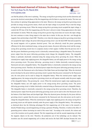
![413 | P a g e
V. CHARGING CIRCUIT
A dynamo attached to a fan’s motor for power generation . [3]The dynamo is attached to the fan’s motor in such
a way that it results in the rotational motion of the dynamo’s shaft. This motion causes the dynamo to produce
electrical energy. The dynamo output is given to the rectifier circuit and then to the voltage regulator and hence
the DC regulated output is used for charging *3yNiMH (nickel metal hydride) Battery.[3]
5.1 Detailed Description
Assume a ceiling fan motor along a generator winding that mainly consists of a motor axle, a stator, and a rotor.
[4]The stator is fixed on the motor axle. In this role, the stator is formed by stacking a predetermined number of
metal plates. The stator is enveloped along a plurality of first magnetizing coils, each of which is winded along a
second magnetizing coil along a generator winding.
The second magnetic coil detects the accept EMF around it. The stator has a predetermined number of same
spaced coil arms in the perpendicular direction near the motor axle. any of the coil arms has a concave section
for the interrelated first magnetizing coil to Wind around. The second magnetic coil detects the received EMF
around it. The stator has a predetermined number of same spaced coil arms in the perpendicular direction toward
the motor axle. Each of the coil arms has a concave section for the interrelated first magnetizing coil to Wind
around. The second magnetizing coil more Winds around the like first magnetizing coil. In particular, each of
the first magnetizing coils is electrically connected along an energy-saving driver governing the circuit. The
energy-saving driver governing circuit receives an input voltage and governs the electrical current phases of the
first magnetizing coils.
The second magnetizing coil is electrically connected along a power distribution governing circuit for
converting the back EMF detected and accepted by the second magnetizing coil to electrical power for output.
The rotor is pivotally mounted on the motor axle through a bearing .In this role, the rotor has particular magnetic
objects around the stator. The magnetic phenomenon can be permanent magnets. The rotor is surrounded along
particular connecting parts for fixing a blade frame. The blade frame has particular blades. The bottom of the
blade frame is pivotally installed along a fluorescent unit. In practice, any of the first magnetizing coils is driven
by the input voltage to developed an induced magnetic field. The rotor is driven to rotate along appreciation the
stator and build up inertia. When the rotor rotates along appreciation the stator, the rotor rotates and cuts through
the magnetic lines. A back EMF is thus generated in the motivates the magnetic field. In this case, the second
magnetizing coil on the stator detects the accepted EMF. The accepted EMF is transformed from the power
delivering the governing circuit into electrical power for output. In this embodiment, the power delivering the
governing circuit is electrically connected along the illuminating unit at the downward of the blade frame. The
electrical power output from the power delivers to the governing circuit can drive the illuminating unit at the
downward of the blade frame. Therefore, the illuminating unit can developed light along out additional electrical
power. However, it should be described that the energy saving driver-governing circuit can convert external AC
power into DC power, and neglect the power supply noise interference.
When the circuit is handling the energy-saving driver governing circuit can find the position of the rotor in
spinning, and therefore calculate the electrical current aspect of individual first magnetizing coils. the energy-
compensating driver governing circuit has a predetermined number of Hall elements. every of the Hall elements](https://image.slidesharecdn.com/researchpaper-170731082244/85/Research-paper-3-320.jpg)
![415 | P a g e
rotates and cuts through the magnetic lines. The back EMF is used by the power delivering governing circuit to
generate electrical power. Therefore, without additional power supply, the research can light up an fluorescent
unit or charge a chargeable battery. Therefore, the research can save energy and reduce the utility cost. The
research along uses an energy saving means on the energy-saving driver governing circuit to supply the input
voltage in an intermittent Way to the energy-saving driver governing circuit. This helps reducing the electrical
power. When the energy-saving driver governing circuit does not receive the input voltage, the rotor still rotates
Along respect to the stator due to inertia and develops a back EMF. In this case, the power delivering governing
circuit can still use the back EMF detected and received by the second magnetizing coil to generate electrical
power. This effectively increases the power generating efficiency of the technology.[4]
5.2 Alternative use of this technique.
These technique is used in every moving systems like wheels of car, bicycle, motorbike etc.
If wheels shaft take as a rotor then we have only providing rotor winding and stator winding and charging
circuit. this construction working like as dynamowhen the wheel shaft rotated that time electricity generated .
This circuit is connected to the battery circuit. So that time battery will charge. when the battery is fully charge
that time, we can drive our car after fuel because due to these electricity car will run using electric power.
Suppose in car used these technique then it stored 4times more electricity, because it has 4wheels which are
rotated. Hence, Our car gives the more mileage, because electricity is generated by rotating speed of wheel by
which of fuel energy. Then our new generation car will become semi-electric car.
VI. CONCLUSION
Alternative use of this technique.
At a time when there is crisis, casting its shadows all over the world one has to look into alternate feasible
sources. One such alternate way to generate power is presented in this paper .The spinning energy of the
dynamo, can be used to operate several small powered devices like a air conditioning compressor Both dynamo
and alternator can be used. The various applications where this power can be used are charging of laptops,
magnetic braking system, cell phones, semi-electric cars etc.
this system used in car to increased the efficiency of engine more than today cars.
Applications
1) Colleges, hospitals, hostels are equipped along at least 50 fans where this energy generating mechanism may
be used to light up the tube lights or charge a battery and power up other devices like computers ,laptops etc.
2) In order to charge cell phone we need a mobile charging circuit which would give the appropriate voltage and
current required for charging the mobile and will be helpful to middle class people to save energy and money.
3) similarly in car storage electric power.
4) Used run compressor in a air conditioning of car.
5) magnetic breaking system.
Advantages
1) Low initial cost: - The initial cost of an electric motor is considerably lower than solar photovoltaic (PV)
panels along the same Output.](https://image.slidesharecdn.com/researchpaper-170731082244/85/Research-paper-5-320.jpg)
![416 | P a g e
2) No emissions of carbon dioxide (Co2), mercury(Ag), nitrogen oxide (N2), sculpture dioxide (Sio2) or
particulate matter into the air, water or soil and helps preserve and protect the environment for future
generations.
3) Minimum maintenance cost once generators are constructed, they can operate efficiently along out any
problems for long period. Additionally, one need not have to check them on a regular basis and extra cost of
generator maintenance could be avoided.
4) Reduces the cost of transmit electricity along the power lines.
DISADVANTAGES
1) The incorporation of dynamo's mechanism may reduce speed of the fan & car
2) The electricity generated by the mechanism will be lesser than the electricity consumed by fan.
3) the design of the car becomes complicated (center gravity, space required)
4) the production cost of the car will increased.
REFERENCES
[1] Amit Roy Rajshahi University of Engineering & Techn..20 PUBLICATIONS Md. Rokunuzzaman
Rajshahi University of Engineering & Techn…
20 PUBLICATIONS
[2] Mayank Grover, B. Lohith Kumar, Isaac Ramalla, International Journal of Scientific and Research
Publications, Volume 4, Issue 12, December 2014 1 1 ISSN 2250-3153
[3] MD Squib Gadara et al, / (IJCSIT) International magazine of Computer Science and Information
Technologies, Vol. 5 (3) , 2014, 3294 – 3297
[4] http://www.appropedia.org/Rowan%27s_portable_pedal_power_generator](https://image.slidesharecdn.com/researchpaper-170731082244/85/Research-paper-6-320.jpg)

This document summarizes a study on generating electricity from a ceiling fan and car wheels. It describes how a dynamo or generator can be attached to a fan motor or car wheels to harness the rotational kinetic energy. The dynamo produces electricity that can be used to directly power small devices or charge batteries. This technique could generate some electricity without external power and reduce energy costs. While it has environmental and cost benefits, incorporating the system may reduce the fan or car speed and the electricity generated would be less than that consumed by the fan.


