This document provides information on pulsed energy devices described by Patrick J. Kelly, specifically focusing on the motor/generator designed by Robert Adams. The summary is:
1) Robert Adams designed an electric motor that uses permanent magnets on the rotor and pulsed electromagnets on the stator. When configured correctly, the output power exceeds the input power by a large margin, such as 800%.
2) The device operates by using power collection coils positioned and timed to contribute back EMF to drive the rotor. Additional electromagnets are pulsed on and off to further boost efficiency beyond 100%.
3) Practical details are provided on components like magnet shape and size, coil dimensions, switching methods and
This predefined speed control of BLDC motor runs a motor at user desired speed by using EEPROM for storing speed. It is an effective speed control method.
Proteger un motor eléctrico o de inducción magnética; primera responsabilidad del equipo electro_ mecánico de la empresa. Con este documento, usted analizará de manera sencilla, como calcular el valor de corriente en amperios (A), mínimo dos (2) o más protecciones que las máquinas rotativas eléctricas requieren según la norma.
Edgar Escobar Castrillón
SENA _ Antioquia _ Colombia
alternators its types and its functions….What you've just experienced is an example of an alternator breathing its last breath.
Your first thought might have been the battery is dying. In a sense, you would be right because the battery and the alternator are related, but the battery tends to get all the press.
This presentation aims to explain the mechanics of alternators, how you can diagnose problems and what you can do if you have a bad alternator.
You will come to now to some background information about alternators and the war of the currents.
working principle of alternators and its kind _What you've just experienced is an example of an alternator breathing its last breath.
Your first thought might have been the battery is dying. In a sense, you would be right because the battery and the alternator are related, but the battery tends to get all the press.
This presentation aims to explain the mechanics of alternators, how you can diagnose problems and what you can do if you have a bad alternator.
You will come to now to some background information about alternators and the war of the currents.
A motor starter is a device designed to:
Start a motor
Accelerate the motor rated speed in the shortest time
Provide protection from overload conditions
A motor starter is therefore a switch with an overload relay.
A motor controller is a device designed to control the operation of a motor. As such it can be
used to control things such as:
Control when the motor starts and stops
How long it runs for
How often the motor run in a given period
Direction of rotation
Explore the innovative world of trenchless pipe repair with our comprehensive guide, "The Benefits and Techniques of Trenchless Pipe Repair." This document delves into the modern methods of repairing underground pipes without the need for extensive excavation, highlighting the numerous advantages and the latest techniques used in the industry.
Learn about the cost savings, reduced environmental impact, and minimal disruption associated with trenchless technology. Discover detailed explanations of popular techniques such as pipe bursting, cured-in-place pipe (CIPP) lining, and directional drilling. Understand how these methods can be applied to various types of infrastructure, from residential plumbing to large-scale municipal systems.
Ideal for homeowners, contractors, engineers, and anyone interested in modern plumbing solutions, this guide provides valuable insights into why trenchless pipe repair is becoming the preferred choice for pipe rehabilitation. Stay informed about the latest advancements and best practices in the field.
Saudi Arabia stands as a titan in the global energy landscape, renowned for its abundant oil and gas resources. It's the largest exporter of petroleum and holds some of the world's most significant reserves. Let's delve into the top 10 oil and gas projects shaping Saudi Arabia's energy future in 2024.
Sachpazis:Terzaghi Bearing Capacity Estimation in simple terms with Calculati...Dr.Costas Sachpazis
Terzaghi's soil bearing capacity theory, developed by Karl Terzaghi, is a fundamental principle in geotechnical engineering used to determine the bearing capacity of shallow foundations. This theory provides a method to calculate the ultimate bearing capacity of soil, which is the maximum load per unit area that the soil can support without undergoing shear failure. The Calculation HTML Code included.
NO1 Uk best vashikaran specialist in delhi vashikaran baba near me online vas...Amil Baba Dawood bangali
Contact with Dawood Bhai Just call on +92322-6382012 and we'll help you. We'll solve all your problems within 12 to 24 hours and with 101% guarantee and with astrology systematic. If you want to take any personal or professional advice then also you can call us on +92322-6382012 , ONLINE LOVE PROBLEM & Other all types of Daily Life Problem's.Then CALL or WHATSAPP us on +92322-6382012 and Get all these problems solutions here by Amil Baba DAWOOD BANGALI
#vashikaranspecialist #astrologer #palmistry #amliyaat #taweez #manpasandshadi #horoscope #spiritual #lovelife #lovespell #marriagespell#aamilbabainpakistan #amilbabainkarachi #powerfullblackmagicspell #kalajadumantarspecialist #realamilbaba #AmilbabainPakistan #astrologerincanada #astrologerindubai #lovespellsmaster #kalajaduspecialist #lovespellsthatwork #aamilbabainlahore#blackmagicformarriage #aamilbaba #kalajadu #kalailam #taweez #wazifaexpert #jadumantar #vashikaranspecialist #astrologer #palmistry #amliyaat #taweez #manpasandshadi #horoscope #spiritual #lovelife #lovespell #marriagespell#aamilbabainpakistan #amilbabainkarachi #powerfullblackmagicspell #kalajadumantarspecialist #realamilbaba #AmilbabainPakistan #astrologerincanada #astrologerindubai #lovespellsmaster #kalajaduspecialist #lovespellsthatwork #aamilbabainlahore #blackmagicforlove #blackmagicformarriage #aamilbaba #kalajadu #kalailam #taweez #wazifaexpert #jadumantar #vashikaranspecialist #astrologer #palmistry #amliyaat #taweez #manpasandshadi #horoscope #spiritual #lovelife #lovespell #marriagespell#aamilbabainpakistan #amilbabainkarachi #powerfullblackmagicspell #kalajadumantarspecialist #realamilbaba #AmilbabainPakistan #astrologerincanada #astrologerindubai #lovespellsmaster #kalajaduspecialist #lovespellsthatwork #aamilbabainlahore #Amilbabainuk #amilbabainspain #amilbabaindubai #Amilbabainnorway #amilbabainkrachi #amilbabainlahore #amilbabaingujranwalan #amilbabainislamabad
Student information management system project report ii.pdfKamal Acharya
Our project explains about the student management. This project mainly explains the various actions related to student details. This project shows some ease in adding, editing and deleting the student details. It also provides a less time consuming process for viewing, adding, editing and deleting the marks of the students.
Welcome to WIPAC Monthly the magazine brought to you by the LinkedIn Group Water Industry Process Automation & Control.
In this month's edition, along with this month's industry news to celebrate the 13 years since the group was created we have articles including
A case study of the used of Advanced Process Control at the Wastewater Treatment works at Lleida in Spain
A look back on an article on smart wastewater networks in order to see how the industry has measured up in the interim around the adoption of Digital Transformation in the Water Industry.
CFD Simulation of By-pass Flow in a HRSG module by R&R Consult.pptxR&R Consult
CFD analysis is incredibly effective at solving mysteries and improving the performance of complex systems!
Here's a great example: At a large natural gas-fired power plant, where they use waste heat to generate steam and energy, they were puzzled that their boiler wasn't producing as much steam as expected.
R&R and Tetra Engineering Group Inc. were asked to solve the issue with reduced steam production.
An inspection had shown that a significant amount of hot flue gas was bypassing the boiler tubes, where the heat was supposed to be transferred.
R&R Consult conducted a CFD analysis, which revealed that 6.3% of the flue gas was bypassing the boiler tubes without transferring heat. The analysis also showed that the flue gas was instead being directed along the sides of the boiler and between the modules that were supposed to capture the heat. This was the cause of the reduced performance.
Based on our results, Tetra Engineering installed covering plates to reduce the bypass flow. This improved the boiler's performance and increased electricity production.
It is always satisfying when we can help solve complex challenges like this. Do your systems also need a check-up or optimization? Give us a call!
Work done in cooperation with James Malloy and David Moelling from Tetra Engineering.
More examples of our work https://www.r-r-consult.dk/en/cases-en/
Final project report on grocery store management system..pdfKamal Acharya
In today’s fast-changing business environment, it’s extremely important to be able to respond to client needs in the most effective and timely manner. If your customers wish to see your business online and have instant access to your products or services.
Online Grocery Store is an e-commerce website, which retails various grocery products. This project allows viewing various products available enables registered users to purchase desired products instantly using Paytm, UPI payment processor (Instant Pay) and also can place order by using Cash on Delivery (Pay Later) option. This project provides an easy access to Administrators and Managers to view orders placed using Pay Later and Instant Pay options.
In order to develop an e-commerce website, a number of Technologies must be studied and understood. These include multi-tiered architecture, server and client-side scripting techniques, implementation technologies, programming language (such as PHP, HTML, CSS, JavaScript) and MySQL relational databases. This is a project with the objective to develop a basic website where a consumer is provided with a shopping cart website and also to know about the technologies used to develop such a website.
This document will discuss each of the underlying technologies to create and implement an e- commerce website.
1. A Practical Guide to Free-Energy Devices Author: Patrick J. Kelly
Chapter 2: Moving Pulsed Systems
Note: If you are not at all familiar with basic electronics, you might find it easier to understand this
chapter if you read chapter 12 first.
There are three categories of pulsed system and we will consider each in turn. These are drive-pulsed
systems, energy-tapping pulsed systems and gravity free-energy pulsing systems. Here we will look at
systems where an electrical pulse is used to cause the device to operate by creating a temporary
magnetic field caused by electric current flowing through a coil or “electromagnet” as it is often called.
Many of these systems are rather subtle in the way that they operate. One very well-known example of
this is
The Motor/Generator of Robert Adams.
The late Robert Adams, an electrical engineer of New Zealand designed and built several varieties of
electric motor using permanent magnets on the rotor and pulsed electromagnets on the frame of the
motor (called the "stator" because it does not move). He found that if they were configured correctly,
then the output from his motors exceeded their input power by a large margin (800%).
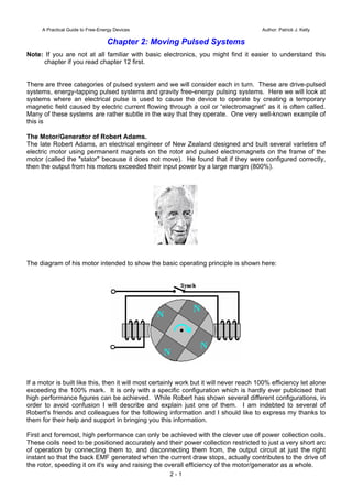
The diagram of his motor intended to show the basic operating principle is shown here:
If a motor is built like this, then it will most certainly work but it will never reach 100% efficiency let alone
exceeding the 100% mark. It is only with a specific configuration which is hardly ever publicised that
high performance figures can be achieved. While Robert has shown several different configurations, in
order to avoid confusion I will describe and explain just one of them. I am indebted to several of
Robert's friends and colleagues for the following information and I should like to express my thanks to
them for their help and support in bringing you this information.
First and foremost, high performance can only be achieved with the clever use of power collection coils.
These coils need to be positioned accurately and their power collection restricted to just a very short arc
of operation by connecting them to, and disconnecting them from, the output circuit at just the right
instant so that the back EMF generated when the current draw stops, actually contributes to the drive of
the rotor, speeding it on it's way and raising the overall efficiency of the motor/generator as a whole.
2 - 1
2. Next, the shape of the magnets used is important as the length to width proportion of the magnet alters
the pattern of it's magnetic fields. In direct opposition to the diagram shown above, the magnets need
to be much longer than their width (or in the case of cylindrical magnets, much longer than their
diameter).
Further, a good deal of experimentation has shown that the size and shape of the electromagnets and
pick-up coils has a major influence on the performance. The cross-sectional area of the core of the
pick-up coils should be four times that of the cross-sectional area of the permanent magnets in the
rotor. The reverse is true for the cores of the drive coils as their cores should have a cross-sectional
area of just one quarter of the rotor magnet cross-sectional area.
Another point which is almost never mentioned is the fact that big circuit gains will not be achieved
unless the drive voltage is high. The minimum should be 48 volts but the higher the voltage, the greater
the energy gain, so voltages in the 120 volts (rectified US mains voltage) to 230 volts (rectified mains
voltage elsewhere) should be considered. Neodymium magnets are not recommended for drive
voltages under 120 volts.
There are several important steps in the way that the Robert Adams motor/generator works and it is
important for you to understand each of the steps.
Step 1: A rotor magnet is attracted to the iron core of a stator “drive” electromagnet. As it approaches
the drive electromagnet, the lines of magnetic force from the stator magnet move across the drive
electromagnet coil. This generates an electric current in the drive electromagnet coil and that current is
fed back to the battery which is powering the motor/generator:
Notice that the movement of the rotor is caused by the permanent magnets being attracted to the iron
cores of the drive electromagnets and not by any electric current. The electric flow is going back into
the battery and is being caused by the movement of the rotor which in turn is being caused by the
permanent magnets.
Step 2: When the rotor turns far enough, the magnets align exactly with the cores of the drive
electromagnets. The rotor continues to rotate because of its inertia, but if we do nothing about it, the
rotor magnet attraction to the drive electromagnet core will act to slow it down and then drag it back to
the drive coil core. We want to prevent that, so we feed a small amount of current into the drive
electromagnet coils – just enough current to stop the backward drag of the rotor magnets. This current
is NOT to push the rotor magnets away, it is just enough to prevent the rotor being slowed down:
2 - 2
3. Step 3: When the rotor magnet has moved away far enough, the current being fed to the drive
electromagnets is cut off. As happens with any coil, when the current is cut off a large reverse voltage
spike is generated. That voltage spike is rectified and fed back to the battery.
The system so far produces a spinning rotor for very little current draw from the battery. But we want
the system to provide us with excess electrical output, so for that, four additional electromagnets are
added around the rotor. These output coils are mounted on a non-magnetic disc which can be rotated
to adjust the gap between the drive coils and the output coils. Like the rotor magnets, the output coils
are spaced evenly around the circumference of the rotor at 90-degree intervals:
2 - 3
Step 4: Surprisingly, the output coils are switched Off for most of the time. This sounds mad but it
most definitely isn’t mad. With the output coils disconnected, the approaching rotor magnets generate
a voltage in the output coil windings but no current can flow. As no current is flowing, no magnetic field
is generated and so the rotor magnets just pull directly towards the output coil iron cores. The
4. 2 - 4
maximum output coil voltage is when the rotor magnets are aligned with the output coil cores. At that
instant the output switch is closed and a strong pulse of current is drawn off and then the switch is
opened again, cutting off the output current. The output switch is closed for only three degrees or so of
the rotor’s rotation and it is off again for the next eighty seven degrees, but the opening of the switch
has a major effect. The switch being opened cuts off the current flowing in the output coils and that
causes a major reverse voltage spike causing a major magnetic field which pushes the rotor on its way.
That voltage spike is rectified and passed back to the battery.
The rectification of every possible spare voltage pulse as described, returns 95% of the drive current to
the battery, making this an extremely effective motor/generator. The performance can be further
enhanced by rotating the set of output coils to find their optimum position and then locking the disc in
place. When properly set up, this generator has an output current which is eight times greater than the
input current.
Notice that the cores of the "generator" pick-up coils are very much wider than the cores of the drive
coils. Also notice the proportions of the magnets where the length is much greater than the width or
diameter. The four generator windings are mounted on a single disc allowing them to be moved
through an angle to find the optimum operating position before being locked in position and the two
drive coils are mounted separately and held clear of the disc. Notice also that the power pick-up coils
are much wider compared to their length than the drive coils are. This is a practical feature which is
explained in greater detail later.
The DC input is shown passing through Robert's custom-made contactor switch which is mounted
directly on the shaft of the motor/generator. This is a mechanical switch which allows an adjustable
On / Off ratio, which is known as the "Mark/Space Ratio" or, if the "On" period is of particular interest,
the "Duty Cycle". Robert Adams indicates that when the motor is running and has been adjusted to it's
optimum performance, then the Mark/Space ratio should be adjusted to minimise the On period and
ideally get it down to about 25% so that for three quarters of the time, the input power is actually
switched off. There are various ways of achieving this switching while still having a very sharp turn on
and turn off of the power.
Robert considered mechanical switching of the drive current to be a very good option although he was
not opposed to using the contact to power a transistor to do the actual switching and so reduce the
current through the mechanical contacts by a major factor. His reasons for his preference for
mechanical switching are that it gives very sharp switching, needs no electrical power to make it
operate and it allows current to flow in both directions. The current flow in two directions is important
because Robert produced various ways of getting the motor to feed current back into the driving
battery, allowing it to drive the motor for long periods without lowering its voltage hardly at all. His
preferred method of switching is shown here:
5. This switching gear operates as follows: The timing disk is bolted securely to the drive shaft of the
motor and its position is set so that the electrical switch-on occurs when the rotor magnet is exactly
aligned with the drive coil core. Adjustment of that timing is done by loosening the locking nut, rotating
the disc very slightly and clamping the disc in position again. A spring washer is used to keep the
assembly tight when the device is running. The disc has a star-shaped piece of copper sheet set into
its surface and two silver-tipped, copper arm "brushes" slide across the surface of the copper star.
One of these two brushes is fixed in position and slides across the copper star near the drive shaft,
making a permanent electrical connection to it. The second brush slides alternatively on the non-
conducting surface of the disc and then over the conducting arm of the copper. The second brush is
mounted so that its position can be adjusted and, because the copper arms taper, that alters the ratio of
the "On" time to the "Off" time. The actual switching is achieved by current flowing through the first
brush, through the copper arm and then through the second brush. The brush arms shown in the
diagram above rely on the springiness of the copper arm to make a good brush-to-copper electrical
connection. It might be preferred to use a rigid brush arm, pivot it and use a spring to ensure a very
good contact between the brush and the copper star at all times.
The adjustment of the On to Off time, or "Mark/Space Ratio" or "Duty Cycle" as the technical people
describe it, could perhaps do with some description. If the moveable brush is positioned near the
centre of the disc, then, because of the tapering of the copper arms, the part of the non-conducting disc
2 - 5
6. that it slides over is shorter and the part of the conducting copper arm with which it connects is longer,
as the two sliding paths are about the same length, the current is on for about the same length as it is
off, giving a Mark/Space ratio of about 50% as shown here:
If, instead, the moveable brush is positioned near the outside edge of the disc, then because of the
tapering of the copper arm, the On path is shorter and the non-conducting Off path is very much longer,
being about three times as long as the On path, giving a Mark/Space ratio of about 25%. As the
moveable brush can be positioned anywhere between these two extremes, the Mark/Space ratio can be
set to any value from 25% to 50%.
The two brushes can be on the same side of the drive shaft or on opposite sides as shown. One
important feature is that the brushes touch in a position where the disc surface is always moving
directly away from the brush mounting, causing any drag to be directly along the arm and giving no
sideways loading on the brush. The diameter of the device is usually one inch (25 mm) or less.
You will also notice that the output is switched although the diagram does not give any indication of how
or when that switching takes place. You will notice that the diagram has angles marked on it for the
optimum positioning of the pick-up coils, well, an Adams Motor builder with a forum ID of "Maimariati"
who achieved a Coefficient Of Performance of 1,223, found that the optimum switching for his motor is
On at 42 degrees and Off at 44.7 degrees. That tiny 2.7 degree part of the rotor turn gives a substantial
power output and cutting the output current off at that point causes the back EMF of the coils to give the
rotor a substantial additional boost on its way. His input power is 27.6 watts and the output power is
33.78 kilowatts
Now for some practical details. It is suggested that a good length for the power pick-up coils can be
determined by using the “paper clip test”. This is done by taking one of the permanent magnets used in
the rotor, and measuring the distance at which that magnet just begins to lift one end of a 32 mm (1.25
inch) paper clip off the table. The optimum length of each coil from end to end is exactly the same as
the distance at which the paper clip starts to lift.
2 - 6
7. The core material used in the electromagnets can be of various different types including advanced
materials and alloys such as ‘Somalloy’ or 'Metglas'. The power pick-up coil proportions are important
as an electromagnet becomes less and less effective as its length increases, and eventually, the part
furthest from the active end can actually be a hindrance to the effective operation. A good coil shape is
one which you would not expect, with the coil width being, perhaps 50% greater than the coil length:
Contrary to what you would expect, the device draws in energy from the local environment better if the
end of the pick-up coil farthest from the rotor is left unaffected by any other part of the device and the
same applies to the magnet facing it. That is, the coil should have the rotor at one end and nothing at
the other end, that is, no second rotor behind the coil. The speed at which the voltage is applied to, and
removed from, the coils is very important. With very sharp voltage rises and falls, additional energy is
drawn from the surrounding environmental energy field. If using transistor switching, then the IRF3205
FET has been found to be very good and a suitable driver for the FET is the MC34151.
If using a Hall-effect semiconductor to synchronise the timing, say the UGN3503U which is very
reliable, then the life of the Hall-effect device is much improved if it is provided with a 470 ohm resistor
between it and the positive supply line, and a similar 470 ohm resistor between it and the negative line.
These resistors in series with the Hall-effect device effectively “float” it and protect it from supply-line
spikes".
Here, two electromagnets are driven by the battery via Robert's 4-arm commutator which is mounted on
the rotor shaft. Some of the recommendations given by Robert are the opposite of what you would
expect. For example, he says that a single rotor construction tends to be more electrically efficient that
one where several rotors are mounted on a single shaft. Robert is against the use of reed switches and
he recommends making one of his commutators.
At one stage, Robert recommended the use of standard transformer shims for constructing the cores of
the electromagnets. This has the advantage that matching bobbins for holding the coil windings are
readily available and can still be used for pick-up coils. Later on, Robert swung towards the use of solid
2 - 7
8. cores from the old PO Series 3000 telephone relays and eventually said that electromagnet cores
should be solid iron.
The diagrams presented by Robert show the magnets located on the rim of the rotor and pointing
outwards. If this is done, then it is essential that the magnets in the rotor are firmly attached on at least
five of their six faces and the possibility of using a ring of non magnetic material such as duct tape
around the outside should be considered. That style of construction also lends itself to streamlining the
rotor by having a completely solid construction, although it might be remarked that the motor would run
better and more quietly if it were enclosed in a box which had the air pumped out of it. If that is done,
then there will be no air resistance and because sound can't pass through a vacuum, quieter operation
is bound to result.
While this may sound a bit complicated, there is no reason why it should be. All that is needed is two
discs and one central disc which is the thickness of the magnets, with slots cut in it, the exact size of
the magnets. The assembly starts with the lower disc, magnets and central disc. These are glued
together, probably with epoxy resin, and that holds the magnets securely on four faces as shown here:
Here, the magnets are attached on the lower face, the right and left faces, and the unused pole face,
and when the upper disc is attached, the upper faces are also secured and there is the minimum of air
turbulence when the rotor spins:
2 - 8
9. There is a "sweet spot" for the positioning of the power pick-up coils and it will usually be found that this
is two or three millimetres away from the rotor. If that is the case, then there will be room for an outer
band of duct tape on the rim of the rotor to provide additional protection against the failure of the
magnet attachment method.
High-power versions of the motor/generator need to be enclosed in a metal box which is earthed as
they are quite capable of generating a substantial amount of high frequency waves which can damage
equipment such as oscilloscopes and create TV reception interference. There would probably be an
improvement in performance as well as a reduction in sound if the box was airtight and had the air
pumped out of it. If that is done, then there will be no air resistance as the rotor spins and since sound
does not pass through a vacuum, quieter operation is possible.
Experienced rotor builders do not like the radial magnets style of construction because of the stresses
on the magnet attachments if high rotational speeds are reached. It should not need to be said, but it is
obviously a major requirement to keep your hands well away from the rotor when the motor is running
as it is perfectly possible to be injured by the high-speed movement if you are careless. Please
remember that this presentation must not be considered to be a recommendation that you build or use
any device of this nature and it must be stressed that this text, in common with the entire contents of
this eBook, is intended to be for information purposes only and no representations or warranties are
implied by this presentation. Should you decide to construct, test or use any device, then you do so
entirely at your own risk and no liability attaches to anybody else if you sustain any kind of injury or
property damage as a result of your own actions.
Because of the mechanical stresses caused during rotation, some experienced constructors feel that
the magnets should be embedded in the rotor as shown here where they are kept well clear of the rim
of a rotor which is made from a tough material. This is so that the outer strip of the material prevents
the magnets breaking loose and becoming dangerous high-speed projectiles, which at best would
destroy the electromagnets and at worst could injure someone quite badly:
2 - 9
10. It needs to be remembered that the proportions of the magnets are for the magnet length to be more
than the diameter, so in cases like this where circular magnet faces are to be used, the magnets will be
cylindrical and the rotor needs to have a significant thickness, which will depend on the magnets which
are available locally. The magnets should be a tight push-fit in their holes and securely glued in place.
Robert Adams has used this construction style as well. However, if an arrangement like this is used,
then there will be a substantial sideways pull on the rotor as it reaches the electromagnet core, tending
to pull the magnets out of the rotor.
It is important that the rotor should be perfectly balanced and have the minimum amount of bearing
friction possible. This calls for precision construction and either roller or ball bearings. The construction
style shown above has the distinct advantage that it has an open end to both the magnet and the coils
and this is believed to facilitate the inflow of environmental energy into the device.
When getting ball-race bearings for an application like this, please be aware that "closed" bearings such
as these are not suitable as supplied:
2 - 10
This is because this type of bearing is usually packed with dense grease which completely destroys its
free motion, making it worse as a bearing than a simple hole-and-shaft arrangement. However, in spite
of this, the closed or "sealed" bearing is popular as the magnets tend to attract dirt and dust and if the
device is not enclosed in a steel box as is necessary for the high power versions, then having the seal
is considered to be an advantage. The way to deal with the grease packing is to soak the bearing in an
11. isopropyal solvent cleaner to remove the manufacturer's grease, and then, when it has dried out,
lubricate the bearing with two drops of a high quality thin oil. If it is intended to house the
motor/generator in an earthed, sealed steel box then an alternative type of bearing which might be
suitable is an open design like this:
especially if the air is removed from the box. Some constructors prefer to use ceramic bearings which
are supposed to be immune to dirt. One supplier is
http://www.bocabearings.com/main1.aspx?p=docs&id=16 but as with everything else, these choices
have to be made by the builder and will be influenced by his opinions.
I'm not sure where it came from, but here is a circuit diagram showing a transistor drive and the return
of the back EMF of the drive coils to the driving power supply. Using this method, about 95% of the
drive current can be returned, lowering the current draw enormously:
The diode feeding the power back to the supply is a Shotky type because of it's high-speed operation.
It needs to be able to handle the peak pulse power and so should be one of the more robust types.
What this circuit does not have is the very important switching on the output coils circuit. Another
strange item is the way that the FET sensor is arranged with two sensors rather than one and with an
additional battery. While it must be admitted that the current draw of the FET gate should be very low,
there still does not seem to be much reason to have a second power supply. One other peculiarity in
this diagram is the positioning of the drive coils. With them offset as shown, it has the effect of them
being at an angle relative to the rotor magnets. It is not at all clear if this is an advanced operating
technique or just poor drawing - I am inclined to assume the latter although I have no evidence for this
other than the circuit design and the low quality of the original drawing which had to be improved
considerably to arrive at the diagram shown above.
2 - 11
The coil generator output should be fed into a capacitor before being passed to whatever equipment is
to be powered by the device. This is because the energy is being drawn from the local environment
12. 2 - 12
and is not conventional energy. Storing it in a capacitor converts it to a more normal version of
electrical power, a feature which has also been mentioned by Don Smith and by John Bedini although
their devices are quite different in operation.
The DC resistance of the coil windings is an important factor. The overall resistance should be either
36 ohms or 72 ohms for a complete set of coils, whether they are drive coils or power pick-up coils.
Coils can be wired in parallel or in series or in series/parallel. So, for 72 ohms with four coils, the DC
resistance of each coil could be 18 ohms for series-connected, 288 ohms for parallel connected, or 72
ohms for connection in series/parallel where two pairs of coils in series are then wired in parallel.
To help with assessing the wire diameter and length which you could use, here is a table of some of the
common sizes in both American Wire Gage and Standard Wire Gauge:
AWG Dia mm SWG Dia mm Max
Amps
Ohms /
100 m
11 2.30 13 2.34 12 0.47
12 2.05 14 2.03 9.3 0.67
13 1.83 15 1.83 7.4 0.85
14 1.63 16 1.63 5.9 1.07
15 1.45 17 1.42 4.7 1.35
16 1.29 18 1.219 3.7 1.48
18 1.024 19 1.016 2.3 2.04
19 0.912 20 0.914 1.8 2.6
20 0.812 21 0.813 1.5 3.5
21 0.723 22 0.711 1.2 4.3
22 0.644 23 0.610 0.92 5.6
23 0.573 24 0.559 0.729 7.0
24 0.511 25 0.508 0.577 8.7
25 0.455 26 0.457 0.457 10.5
26 0.405 27 0.417 0.361 13.0
27 0.361 28 0.376 0.288 15.5
28 0.321 30 0.315 0.226 22.1
29 0.286 32 0.274 0.182 29.2
30 0.255 33 0.254 0.142 34.7
31 0.226 34 0.234 0.113 40.2
32 0.203 36 0.193 0.091 58.9
33 0.180 37 0.173 0.072 76.7
34 0.160 38 0.152 0.056 94.5
35 0.142 39 0.132 0.044 121.2
So far, we have not discussed the generation of the timing pulses. A popular choice for a timing system
is to use a slotted disc mounted on the rotor axle and sensing the slots with an "optical" switch. The
"optical" part of the switch is usually performed by UV transmission and reception and as ultra violet is
not visible to the human eye, describing the switching mechanism as "optical" is not really correct. The
actual sensing mechanism is very simple as commercial devices are readily available for performing the
task. The sensor housing contains both a UV LED to create the transmission beam, and a UV
dependent resistor to detect that transmitted beam.
Here is an example of a neatly constructed timing mechanism made by Ron Pugh for his six-magnet
rotor assembly:
13. and the switch/sensor:
This device happens to be one which is supplied by www.bayareaamusements.com under their
product code number : OP-5490-14327-00. As the slotted disc rotates, one of the slots comes opposite
the sensor and allows the UV beam to pass through to the sensor. That lowers the resistance of the
sensor device and that change is then used to trigger the drive pulse for whatever length of time the slot
leaves the sensor clear. You will notice the balanced attachment method used by Ron to avoid having
an unbalanced rotor assembly. There can be two timing discs, one for the drive pulses and one for
switching the power pickup coils in and out of the circuit. The slots in the power pick-up timing disk will
be very narrow as the switch-on period is only about 2.7 degrees. For a six-inch diameter disc where
360 degrees represents a circumference length of 18.85 inches (478.78 mm) a 2.7 degree slot would
be only 9/64 inch (3.6 mm) wide. The arrangement for an axial magnet rotor set-up could be like this:
So to recap, the things which are necessary for getting an Adams Motor output into the serious bracket
are:
2 - 13
14. 1. A performance of COP>1 can only be achieved if there are power pick-up coils.
2. The rotor magnets need to be longer than they are wide in order to ensure the correct magnetic field
shape and the rotor must be perfectly balanced and have bearings as low-friction as possible.
3. The face area of the rotor magnets needs to be four times that of the drive coil cores and one quarter
the area of the core of the power pick-up coils. This means that if they are circular, then the drive coil
core diameter needs to be half the diameter of the magnet and the magnet diameter needs to be half
the diameter of the power pick-up core. For example, if a circular rotor magnet is 10 mm across,
then the drive core should be 5 mm across and the pick-up core 20 mm across.
4. The drive voltage needs to be a minimum of 48 volts and preferably, a good deal higher than that.
5. Do not use neodymium magnets if the drive voltage is less than 120 volts.
6. The drive coils should not be pulsed until they are exactly aligned with the rotor magnets even though
this does not give the fastest rotor speed.
7. Each complete set of coils should have a DC resistance of either 36 ohms or 72 ohms and definitely
72 ohms if the drive voltage is 120 volts or higher.
8. Collect the output power in large capacitors before using it to power equipment.
It may also be possible to boost the output power further, by using the Coil-Shorting technique shown in
the section of this chapter on the RotoVerter.
If you want the original drawings and some explanation on the operation of the motor, then two
publications from the late Robert Adams can be bought from www.nexusmagazine.com where the
prices are quoted in Australian dollars, making the books look much more expensive than they actually
are.
http://www.totallyamped.net/adams/index.html is a really impressive collection of well-informed practical
material on building and using an Adams motor with details of sensors and how they work, core
materials and their performances and how to locate the "sweet spot" - very highly recommended web
site.
Tewari Paramahamsa’s ‘Reduced Reaction’ Generator
In April 2015, the famous 80-year old Indian scientist Tewari (www.tewari.org) well-known for his use of
the homopolar generator to produce large volumes of hydrogen for commercial use, announced his new
generator design and his corresponding patent application, shown below, was published. His claim for
a Lenz-reduced operation have produced performances between COP=2 and COP=3. Here is a
picture of a prototype, which is held together by four spring-loaded straps. The coils are held in place
inside the frame and permanent magnets are spun inside those frames:
2 - 14
15. The principle of operation is simple and elegant. The power output conductors are arranged in such a
way so that half of the magnetic field generated by the output current (that is, the magnetic field which
opposes the motor spinning the rotor) is in one direction and the remaining half is in the opposite
direction, cancelling the effect of the first half. The result is an arrangement where increasing power
output has no noticeable effect on the input power. In other words, the Lenz Law drag effect has been
effectively overcome. Tewari is due our warmest congratulations for what he has achieved. Being
sensible, Tewari does not mention anything about 20 kilowatts of self-powered output, but instead, puts
the design forward as being an improvement in the design of existing generators – and it is most
certainly that. Here is his patent application:
US Patent Application 2015/0084467 A1 26 Mar 2015 Inventor: Tewari Paramahamsa
Reduced Reaction Rotary Alternating Current Generator
Abstract:
A reduced reaction alternating current generator including a hollow stator core, a cylindrical rotor within
the stator, a freely rotating shaft coupled to the rotor, a first set of magnets in which the south pole of
each magnet is coupled to the surface of the rotor and the north pole of each magnet is facing the inner
surface of the hollow stator core, a second set of magnets in which the north pole of each magnet is
coupled to the surface of the rotor and the south pole of each magnet is facing the inner surface of the
hollow stator core, and a set of silicon steel pieces coupled to the outer surface of the rotor comprised
of individual silicon steel pieces positioned adjacent to and longitudinally in line with each individual
magnet within the first set of magnets and each individual magnet within the second set of magnets.
Description:
BACKGROUND OF THE INVENTION
Michael Faraday discovered the principles of electromagnetic induction and invented the rotating
electrical generator in 1832. The generator was known as the Unipolar Generator, Acyclic Generator
and Disk Generator. This generator operated on the principle that voltage is induced in a conductor in
relative motion to an external magnetic field. Moreover, when the conductor is configured as a closed
circuit and is in relative motion with an external magnetic field, a current will be induced to flow through
that circuit. The induced current itself will generate an induced magnetic field surrounding the
conductor. The direction of the induced current is determined by Fleming's right hand rule which states
that the magnetic field produced by the current induced in the conductor will repel the external magnetic
field which induced the current in the conductor. As such, the induced magnetic field surrounding the
2 - 15
16. 2 - 16
conductor and the external magnetic field repel each other so as to create a torque on the conductor
which opposes that conductor's movement relative to the external magnetic field. Faraday's generator
and all subsequent generators have in common, the production of this counter or back-torque.
The efficiency of an electrical generator is governed by mechanical and electrical limitations. The
mechanical limitations include windage and friction of the generator's rotor and bearings. The electrical
limitations include electrical impedance within the windings of the generator as well as the above-
described counter or back-torque.
A prime mover is attached to a generator so as to cause the rotation of the generator's rotor resulting in
the production of either a direct or an alternating current within the generator's conductor and a back-
torque which counters the rotation caused by the prime mover. The prime mover may be powered by
steam, wind or water. Therefore, the problem with standard generators is that their efficiency is limited
due to back-torque generated as a result of current induced within the generator's conductor windings.
DEFINITIONS
The following definitions are provided for convenience and are not to be taken as a limitation of the
present invention.
Fleming's Left Hand Rule refers to the effect that when a current flows in a conductor and an external
magnetic field is applied across that current flow, the conductor will experience a force perpendicular to
both the external magnetic field and the direction of the current flow. The Left Hand Rule can be used
to represent three mutually orthogonal axes using the thumb to represent a mechanical force, the first
finger to represent a magnetic field and the middle finger to represent the current, each finger
positioned at right angles to each other.
Synchronous generator refers to an electrical generator which turns at the same speed as the drive
mechanism, also known as the synchronous speed. A synchronous generator produces an alternating
current and voltage at a frequency proportional to the rotation speed and to the number of excitation
poles internal to the generator.
Asynchronous generator refers to an alternating current generator that uses the principles of induction
to produce power. Asynchronous generators operate by mechanically turning their rotor faster than the
synchronous speed, giving negative slip.
Low carbon steel refers to steel containing less carbon than other steels. This steel is inherently easier
to cold-form due to its soft and ductile nature.
Grain-oriented electrical steel refers to sheet steel used for laminations in power transformers having a
silicon level of 3% or less.
SUMMARY OF THE INVENTION
It is the primary purpose of the present invention to overcome the above problems by providing a
reduced reaction rotating alternating current generator providing improvement in efficiency
characteristics not currently available in standard alternating current generators.
To accomplish this objective, according to one embodiment of the present invention a reduced reaction
alternating current generator is disclosed comprising a hollow stator core having an axis comprised of
longitudinally positioned sheets laminated with a high permeability magnetic material, the laminated
sheets including longitudinally embedded slots in which a conductor winding is laid parallel to the axis,
a cylindrical rotor concentric with and positioned inside the hollow stator core comprised of a high
permeability magnetic material and a shaft coupled to the rotor and driven by an external source so as
to freely rotate the rotor relative to the hollow stator core. The generator comprises a first set of
magnets in which the south pole of each magnet is coupled to the surface of the rotor and the north
pole of each magnet is facing the inner surface of the hollow stator core, a second set of magnets in
which the north pole of each magnet is coupled to the surface of the rotor and the south pole of each
magnet is facing the inner surface of the hollow stator core and a set of silicon steel pieces coupled to
17. 2 - 17
the outer surface of the rotor comprised of individual silicon steel pieces positioned adjacent to and
longitudinally in line with each individual magnet within the first set of magnets and each individual
magnet within the second set of magnets.
In addition to the foregoing, other features, objects and advantages of the present invention will become
apparent from the following description.
BRIEF DESCRIPTION OF THE DRAWINGS
The following detailed description, which is given by way of example only, will best be appreciated in
conjunction with the accompanying drawings in which:
Fig.1 depicts a longitudinal cross-sectional view of a reduced reaction alternating current generator
according to an example embodiment of the present invention;
Fig.2 depicts an end cross-sectional view of a reduced reaction alternating current generator according
to an example embodiment of the present invention;
Fig.3 depicts a centre cross-sectional view of a reduced reaction alternating current generator
according to an example embodiment of the present invention;
Fig.4 depicts a longitudinal cross-sectional view of the flow of magnetic fields emanating from the first
set of magnets within a reduced reaction generator according to an example embodiment of the present
invention;
Fig.5 and Fig.6 depict the interaction between the magnetic flux originating from the north poles of the
first set of magnets and the magnetic flux resulting from an induced current in the conductor winding
according to an example embodiment of the present invention;
Fig.7 depicts a longitudinal cross-sectional view of the flow of magnetic fields emanating from the
second set of magnets within a reduced reaction generator accordance to an example embodiment of
the present invention; and
Fig.8 and Fig.9 depict the interaction between the magnetic flux originating from the south poles of the
second set of magnets and the magnetic flux resulting from an induced current in the conductor winding
according to an example embodiment of the present invention.
DETAILED DESCRIPTION OF THE INVENTION
The present invention relates to a reduced reaction rotating alternating current generator providing
improvement in efficiency characteristics not currently available in standard alternating current
generators.
18. Fig.1 depicts a longitudinal cross-sectional view of a reduced reaction alternating current generator
according to an example embodiment of the present invention. As shown in Fig.1, the induction
machine 100 comprises a shaft 101, a rotor 102, a stator 103, a first set of magnets 104, a second set
of magnets 105 (not shown), a conductor winding 106 and silicon steel pieces 107.
The rotor 102 is a cylinder of high permeability magnetic material attached directly to the shaft 101
using any conventional known method that provides for a secure and permanent bonding under normal
operating conditions. The rotor 102 is dimensioned so as to be fully enclosed within the stator 103 while
the shaft 101 extends beyond one or both ends of the stator 103.
The shaft 101 is mounted within the stator 103 so as to allow the shaft 101 and the attached rotor 102
to rotate freely within the stator 103 when the shaft 101 is driven by an external drive source. The
external drive source is coupled to one end of the shaft 101 that extends beyond the stator 103. The
external drive source may be driven either at a variable speed or at a synchronous speed. As such the
drive source may be an alternating current (AC) based source or a direct current (DC) based source.
The drive source may also be a non-electric based drive source such as a hydro, wind or an internal
combustion based source. The means of coupling the drive source to the shaft 101 will be dependent
on the type of drive source and any conventionally known means appropriate to that drive source type.
In an example embodiment, the shaft is 30 mm diameter 1018 steel, the rotor is 370 mm diameter 1018
steel and the stator has a 570 mm diameter.
Provisions are made on the cylindrical surface of the rotor 102 for the mounting of the first set of
magnets 104 and for the mounting of the second set of magnets 105 near each of the ends of the rotor
102. Provisions are also made for the mounting of the silicon steel pieces 107 on the rotor at positions
near the centre of the rotor.
The first set of magnets 104 and the second set of magnets 105 (not shown) are attached to the ends
of the rotor cylinder 102 using any conventional method known to provide a secure and permanent
bonding under normal operating conditions. Each end of the rotor 102 contains one of the first set of
magnets 104 and one of the second set of magnets 105, for a total of four magnets. The first set of
magnets 104 are oriented with their north poles facing the stator 103 and their south poles coupled to
the rotor 102. The second set of magnets 105 (not shown) are oriented with their south poles facing
the stator 103 and their north poles coupled to the rotor 102. The magnets may be permanent magnets
or electromagnets.
2 - 18
19. 2 - 19
In an example embodiment, the permanent magnets are Neodymium magnets with a maximum energy
product (BHmax) of 48 to 50 MGOe. Moreover, in another example embodiment, the electromagnets are
radial pole and are attached to the rotor in a manner generally known in the industry.
The silicon steel pieces 107 are also attached to the rotor 102 using any conventional method known to
provide a secure and permanent bonding under normal operating conditions. There is a single silicon
steel piece 107 corresponding to each magnet of the first and second sets of magnets 104 attached to
the rotor 102. Each silicon steel piece 107 is positioned in line with its corresponding magnet leaving a
predefined distance 109 between silicon steel piece and its corresponding magnet. Each silicon steel
piece 107 is comprised of silicon steel which is a speciality steel tailored to have a small magnetic
hysteresis area and high magnetic permeability. A high magnetic permeability is defined as having a
magnetic saturation level above 1.8 Teslas.
In an example embodiment, the first and second sets of magnets 104, 105 and the silicon steel pieces
107 are each dimensioned to have approximately the same surface area and the distance 109 between
silicon steel piece and a corresponding magnet is no more than the length of the magnet in the axial
plane.
The rotor 102 and the attached magnets 104, 105 and steel pieces 107 are each sized as to provide for
an air-gap 108 of a predetermined size between the outer surfaces of the attached magnets 104, 105
and silicon steel pieces 107 and the inner surface of the stator 103. The air gap is chosen to provide
free rotation of the rotor 102 and the attached first and second sets of magnets 104, 105 within the
stator 103 as well as the efficient flow of magnetic flux into and out of the stator 103 across the air-gap
108. In an example embodiment, the air-gap 108 is within a range of 3 mm to 10 mm.
The stator 103 is composed of longitudinally placed silicon steel laminates having grains oriented along
the path of the magnetic flux that enters and exits the stator 103. The stator 103 also includes
longitudinally oriented slots in which the conductor winding 106 is laid, the conductor winding 106
positioned such as to be cut through by the rotating magnetic flux originating from the first and second
sets of magnets 104 attached to the rotating motor 102.
In an example embodiment, the stator is comprised of a magnetically inert material, such as PVC
piping, of suitable strength to support grain oriented steel lamination sheets.
In an example embodiment, the magnetic flux emanating from the first and second magnets is
approximately 10,000 Gauss.
20. Fig.2 depicts an end cross sectional view of a reduced reaction alternating current generator according
to an example embodiment of the present invention. As shown in Fig.2 the first set of magnets 104
with their north poles facing the stator 103 and their south poles coupled to the rotor 102 are positioned
at opposing in-line positions on one end of the rotor 102.
Similarly, the second set of magnets 105 with their south poles facing the stator 103 and their north
poles coupled to the rotor 102 are positioned at opposing in-line positions on the same end of the rotor
102 at a ninety degree offset from the first set of magnets 104. An identical first set of magnets 104 and
second set of magnets 105 are coupled to the other end of the rotor 102 at similar positions.
2 - 20
21. Fig.3 depicts a centre cross sectional view of a reduced reaction alternating current generator
according to an example embodiment of the present invention. As shown in Fig.3, a single silicon steel
piece 107 is positioned longitudinally in line with each magnet of the first and second sets of magnets
104, 105 (not shown). The position of each silicon steel piece 107 provides for a predefined distance
108 between a silicon steel piece 107 and its corresponding magnet.
In an example embodiment, the distance between a silicon steel piece 107 and its corresponding
magnet is equal to the longitudinal length of the magnet.
Referring again to Fig.1, an electromagnetic force (EMF) is created across the conductor winding 106
embedded within the stator 103 when the magnetic flux emanating from the first set of magnets 104
and from the second set of magnets 105 cut through the conductor winding 106 as the rotor 102
rotates. Looking in the direction of arrow C in Fig.1, with the rotor 102 turning in a clockwise direction
and the magnetic flux emanating in a vertically upward direction from the north poles of the first set of
magnets 104, the current generated as a result of the induced electromagnetic force will travel from left
to right 110 within the conductor winding 106.
The current direction is as per Lenz's Law which states when an electric current is induced in a
conductor, the direction of the induced current is such that its magnetic effect will oppose the action that
gives rise to the induced current. As such, the direction of the induced current 110 results in a torque
such as to oppose the clockwise rotation of the rotor 102. Specifically, looking in the direction of the
arrow C in Fig.1, the interaction between the counter-clockwise magnetic field surrounding the
conductor as a result of the induced electromagnetic force and the upward magnetic flux emanating
from the north poles first pair of magnets 104 will create a counter-clockwise torque opposing the
clockwise rotation of the rotor 102.
2 - 21
22. Fig.4 depicts a longitudinal cross sectional view of the flow of magnetic fields emanating from the first
set of magnets within a reduced reaction generator. As shown in Fig.4, the magnetic flux 401
emanating from the north poles of the first set of magnets 104 travels vertically upwards, across the air
gap 108 and into the stator 103 as the magnetic flux 401 rotates with the rotor 102 relative to the stator
103. As this rotating magnetic flux 401 enters the static stator 103, it cuts sideways across the
conductor winding 106 embedded within the stator 103 and induces a current within the conductor
winding 106.
Within the stator 103, a portion of magnetic flux 402 is now trapped within the grain stampings within
the stator 103 and flows longitudinally in an effort to return to a corresponding south pole of the first set
of magnets 104. This portion of the magnetic flux 402 is now static relative to the stator 103 and the
embedded conductor winding 106. As such, this portion of the magnetic flux 402 flows through and
exits the stator 103 without any sideways movement relative to the embedded conductor winding 106
and therefore without inducing a current within the conductor winding 106.
Outside the stator 103, a portion of the magnetic flux 403 crosses the air gap 108 and reaches the
surface of a corresponding steel piece 107. The steel piece 107 focuses the magnetic flux 403 within
the air gap 108 providing a more efficient and specifically designed path for the magnetic flux 403 to
return to a corresponding first set of magnets 104. The magnetic flux 403 passes through the steel
piece 107 and returns to a corresponding south pole of the first set of magnets 104 thereby closing the
magnetic flux loop between north and south poles of each magnet of the first set of magnets 104.
2 - 22
23. Fig.5 and Fig.6 depict the interaction between the magnetic flux originating from the north poles of the
first set of magnets and the magnetic flux resulting from an induced current in the conductor winding. In
both Fig.5 and Fig.6, the current 110 induced in the conductor winding 106 by the clockwise rotation of
the rotor 102 is shown coming out of the page. Moreover, in accordance with the application of the
right hand rule, the magnetic flux 501 surrounding the conductor winding 106 as a result of the induced
current 110 is shown as having a counter-clockwise rotation.
In Fig.5, the magnetic flux originating from the first set of magnets is shown traversing the air gap
upwards and interacting with the magnetic flux surrounding the conductor winding. As shown in Fig.5,
the magnetic field 401 originating from the first set of magnets 104 is strengthened on the right side of
the conductor winding 106 due to the superimposition of the magnetic field 501 induced in the
conductor winding 106 in the same direction. However, the magnetic field 401 originating from the first
set of magnets 104, is weakened on the left side of the conductor winding 106 due to the
superimposition of the magnetic field 501 induced in the conductor winding 106 in the opposite
direction. As a result of this interaction, the net magnetic field in the air-gap 108 over the surfaces of
the first set of magnets 104 results in the application of a counter-clockwise torque 502 to the rotor 102
which opposes the clockwise rotation of the rotor 102. This is in accordance with Lenz's Law and is
confirmed by the right hand rule which shows that a conductor within an upward directed magnetic field
and carrying a current in the induced direction (coming out of the page) will experience a counter-
clockwise force.
2 - 23
24. In Fig.6, the portion of the magnetic flux which is routed back from the stator, downwards across the air
gap and through a silicon steel piece is shown interacting with the induced magnetic flux surrounding
the conductor winding. As shown in Fig.6, the magnetic field 403 routed down through the silicon steel
piece 107 is strengthened on the left side of the conductor winding 106 due to the superimposition of
the magnetic field 501 induced in the conductor winding 106 in the same direction. However, the
magnetic field 403 is weakened on the right side of the conductor winding 106 due to the
superimposition of the magnetic field 501 induced in the conductor winding 106 in the opposite
direction. As a result, on the surface of the silicon steel piece 107, the magnetic field 403 develops a
gradient from left to right thus creating a clockwise torque 602 which supports the clockwise rotation of
the rotor 102. This is in accordance with Lenz's Law and is confirmed by the right hand rule which
shows that a conductor winding 106 within a downward directed magnetic field 403 and carrying a
current 110 in the induced direction (coming out of the page) will experience a clockwise force.
Therefore, as a result of this configuration, the conductor winding 106 embedded within the stator 103
is cut at two places by each magnetic flux originating from the north pole of the first set of magnets 104.
Specifically, a first time when the magnetic field 401 enters the stator 103 in an upward direction and a
second time when the magnetic field 403 exits the stator 103 in a downward direction through a silicon
steel piece 107. The net effect is that the clockwise torque generated by the magnetic field 403 rerouted
through the silicon steel pieces 107 partially cancels the counter-clockwise torque generated by the
magnetic field 401 originating from the north poles of the first set of magnets 104. This results in a
partial nullification of the back torque reaction caused by the effect of Lenz's Law reaction and results in
a corresponding increase in the efficiency of the machine because the external drive source has to
supply less torque to overcome the reduced reaction of the machine.
2 - 24
25. Fig.7 depicts a longitudinal cross-sectional view of the flow of magnetic fields emanating from the
second set of magnets within a reduced reaction generator. As shown in Fig.7, the magnetic flux 701
flowing into the south pole of the second set of the magnets 105 travels vertically downwards from
within the stator 103 and across the air gap 108 as the magnetic flux 701 rotates with the rotor 102
relative to the stator 103. As this rotating magnetic flux 701 exits the static stator 103, it cuts sideways
across the conductor winding 106 embedded within the stator 103 and induces a current within that
conductor winding 106.
Within the stator 103, a portion of the magnetic flux 702 flows longitudinally along the grain stampings
within the stator 103 from a position where the magnetic flux 702 enters the stator 103. This portion of
the magnetic flux 702 is static relative to the stator 103 and to the conductor winding 106 embedded
within the stator 103. As such, this portion of the magnetic flux 702 enters and flows through the stator
103 without any sideways movement relative to the embedded conductor winding 106 and, therefore,
without inducing a current within the conductor winding 106.
Outside the stator 103, a portion of the magnetic flux 703 flows from a north pole of the second set of
magnets 105, through a corresponding silicon steel piece 107, upwards across the air gap 108 and into
the stator 103. The silicon steel piece 107 focuses the magnetic flux 703 within the air gap 108
providing a more efficient and specifically designed path for the magnetic flux 703 originating from a
corresponding second set of magnets 105. The magnetic flux 703 exists the steel piece 107 and enters
the stator 103 thereby closing the magnetic flux loop between the south and north poles of each
magnet of the second set of magnets 105.
Fig.8 and Fig.9 depict the interaction between the magnetic flux originating from the south poles of the
second set of magnets and the magnetic flux resulting from an induced current in the conductor
winding. In both Fig.8 and Fig.9, the current 110 induced in the conductor winding 106 by the
clockwise rotation of the rotor 102 is shown as going into the page. Moreover, in accordance with the
application of the right hand rule, the magnetic flux 801 surrounding the conductor winding 106 as a
result of the induced current 110 is shown as having a clockwise rotation.
2 - 25
26. In Fig.8, the magnetic flux originating from the second set of magnets is shown traversing the air gap
downwards and interacting with the magnetic flux surrounding the conductor winding. As shown in
Fig.8, the magnetic field 701 originating from the second set of magnets 105 is strengthened on the
right side of the conductor winding 106 due to the superimposition of the magnetic field 801 induced in
the conductor winding 106 in the same direction. However, the magnetic field 701 originating from the
second set of magnets 105 is weakened on the left side of the conductor winding 106 due to the
superimposition of the magnetic fields 801 induced in the conductor winding 106 in the opposite
direction. As a result of this interaction, the net magnetic field in the air-gap over the surfaces of the
second set of magnets 105 results in the application of a counter-clockwise torque 802 to the rotor 102
which opposes the clockwise rotation of the rotor 102. This is in accordance with Lenz's Law and is
confirmed by the right hand rule which shows that a conductor within a downwards directed magnetic
field and carrying a current in the induced direction (going into the page) will experience a counter-
clockwise force.
2 - 26
27. In Fig.9, the portion of the magnetic flux originally routed through the steel pieces 107, across the air
gap 108 and into the stator is shown interacting with the induced magnetic flux surrounding the
conductor winding. As shown in Fig.9, the magnetic field 703 routed upwards through a steel piece
107 and across the air gap 108 is strengthened on the left side of the conductor winding 106 due to the
superimposition of the magnetic field 801 induced in the conductor winding 106 in the same direction.
However, the magnetic field 703 is weakened on the right side of the conductor winding 106 due to the
superimposition of the magnetic field 801 induced in the conductor winding 106 in the opposite
direction. As a result, on the surface of the silicon steel piece 107, the magnetic field 703 develops a
gradient from left to right thus creating a clockwise torque 902 which supports the clockwise rotation of
the rotor 102. This is in accordance with Lenz's law and is confirmed by the right hand rule which
shows that a conductor winding 106 within an upwards directed magnetic field 703 and carrying a
current 110 in the induced direction (going into the page) will experience a clockwise force.
Therefore, as a result of this configuration and as described above for the first set of magnets, the
conductor embedded within the stator is cut at two places by each magnetic field terminating at the
south pole of the second set of magnets. Specifically, a first time when the magnetic field 701 exits the
stator 103 in a downward direction and a second time when the magnetic field 703 enters the stator 103
in an upward direction through a silicon steel piece 107. The net effect is that the clockwise torque
generated by the magnetic field 703 rerouted through the silicon steel pieces 107 partially cancels the
counter-clockwise torque generated by the magnetic field 701 terminating at the south pole of the
second set of magnets 105. This results in a partial nullification of the back torque reaction caused by
the effect of Lenz's Law reaction and results in a corresponding increase in the efficiency of the
machine because the external drive source has to supply less torque to overcome the reduced reaction
of the machine.
Lidmotor’s Low-voltage Rotor
One very experienced developer whose YouTube ID is “Lidmotor” (because he makes motors from the
lids of jars) has a short video at https://www.youtube.com/watch?v=SjWCprVXer8 showing a very
simple rotor design with one of his jar lids mounted on a single bearing:
2 - 27
28. The white lid has four magnets attached to it spaced out evenly around the lid at ninety-degree
intervals. Facing them is an air-core coil mounted on a non-magnetic support dowel and wound with
400 turns of ’30-gauge’ wire on a plastic spool. As ‘Lidmotor’ is American, the ’30 gauge’ wire is likely
to be American Wire Gauge #30 with a diameter of 0.255 mm as opposed to the European Standard
Wire Gauge size which has a 0.315 mm diameter. An air-core coil has no effect on the passing rotor
magnets IF it is not carrying current. An output coil will cause drag on the rotor if current is being drawn
from the coil, and so timed output switching as used by Robert Adams would be needed to not just
overcome the drag, but to push the rotor on its way as well.
There are two very important features of this rotor drive design. One is the fact that a supercap (10-
Farad, 2.3V) is used to drive the rotor and when supplied with a charge of only 0.5V to 1.0V, can spin
the rotor for up to thirty minutes. That very long time is likely to be a feature of the second important
item which is that he has placed an LED across the reed switch used to power the coil. When the reed
switch opens, a back-EMF voltage spike occurs and the LED feeds that voltage pulse back into the
100% efficient supercap, recovering most of the current used to drive the rotor. This is the same
method as used by Robert Adams in his motor designs. Lidmotor presents his circuit like this:
While the circuit shows the magnet operating the reed switch as being 180 degrees around from the
coil, the photograph indicates that the switching magnet is one 90 degrees away. Any of the other
magnets can be used. The reed switch operation is adjusted to get the best performance. This is done
by moving the switch backwards and forwards along the moving path of the magnet to make the
switching occur earlier or later. The objective is to push the rotor magnet on its way by pulsing the coil
very briefly just after the rotor magnet has passed the centre of the coil. The length of time that the
2 - 28
29. reed switch is closed can be adjusted by moving the switch closer to the magnet for a longer switch-
closed time, or further away for a shorter switch closure. It is also possible to alter the closed time by
positioning the switch across the path of the magnet travel or parallel to it.
If you are not familiar with a reed switch, it is just a glass tube, filled with an inert gas, and with two
overlapping metal strips inside the tube:
The external magnetic field magnetises the strips and they spring together due to magnetic attraction
and spring apart again when the magnetic field moves away. These switches come in various sizes
and the smallest version tends to be unreliable and has a very low maximum current capacity. The
larger versions are much more robust.
Lidmotor’s circuit is very simple and very effective, even though the rotor will have minimal weight and
no significant drag. One wonders if adding a second coil and a diode feeding the supercapacitor, if the
system could not become self-running.
Teruo Kawai’s COP=3.18 Magnetic Motor.
In July 1995, a patent was granted to Teruo Kawai of Japan, for an electric motor. In the patent, Teruo
states that a measured electrical input of 19.55 watts produced an output of 62.16 watts, and that is a
COP of 3.18. The main sections of that patent are included in the Appendix.
This is an interesting design which has twelve stator electromagnets surrounding a rotor which has
three magnetic poles:
The left hand diagram shows the front face of the motor with its twelve red electromagnets surrounding
an unusually shaped steel rotor (coloured yellow).
The right hand diagram shows a cross-section through the motor. The blue rectangles are permanent
magnets which Teruo describes as being “a ring of permanent magnets” although it is not immediately
obvious why a ring magnet should not be used – perhaps none with the necessary diameters were
available. He also says that the magnets are bolted to the rotors.
2 - 29
30. The frame material supporting the ball bearings and electromagnets is any suitable non-magnetic
material and while aluminium is mentioned, I would strongly recommend that neither aluminium nor
copper is used, especially since plastic chopping board material is very cheap and highly robust.
The rotor and stator are somewhat unusual:
Because of the inner magnets, each of the steel rotors have three poles each – three North poles at
one end and three South poles at the other end. The axle of the motor is made of good quality
stainless steel as that is both robust and non-magnetic.
The switching of the supply current is similar to that of the Charles Flynn magnet motor, and Teruo’s
motor has been measured with COP>3 which means that the output power is more than three times
greater than the input power.
The input power switching occurs four times per revolution and it occurs just as the leading edge of a
rotor arm approaches an electromagnet (the electromagnets shown in blue are powered up):
2 - 30
31. Here, the electromagnets shown in blue have just been powered up and this draws the yellow rotor
arms in a clockwise direction towards those powered up electromagnets. The magnetic force is in
attraction mode and while this is slightly less powerful than repulsion mode, it does not have an adverse
effect on the magnets which should remain in top condition for many years.
The switching suggested is the same as for the Charles Flynn motor, and that is an optical timing disc
mounted on the axle shaft:
While Teruo shows various alternative versions of the motor, he states the result of a test run on the
motor: “Pure steel was used as a magnetic material. It was 30 mm thick with teeth of 218 mm diameter
and notches of 158 mm diameter. A 1000 gauss ferrite magnet was used as the permanent magnet.
Electric power of 19.55 watts was applied to the electromagnets (17 volts at 1.15 amps). This produced
100 rpm with a torque of 60.52 Kg-cm and an output of 62.16 watts”.
While an optical switching disc certainly works well, it will produce a rotational speed which is
determined by the power supply and the load. I suggest that a simple divide-by-four power supply
would give speed control:
James Hardy’s Self-Powered Water-Pump Generator.
There is a video on Google which shows an interesting self-powered water-pump driven, electrical
generator at: http://www.youtube.com/watch?v=IGpXA6qhH_Q
2 - 31
32. This is a very simple device where the jet of water from the pump is directed at a simple water-wheel
which in turn, spins an electrical alternator, powering both the pump and an electric light bulb,
demonstrating free-energy.
Initially, the generator is got up to speed, driven by the mains electrical supply. Then, when it is running
normally, the mains connection is removed and the motor/generator sustains itself and is also able to
power at least one light bulb. The generator output is normal mains current from a standard off-the-
shelf alternator.
James has Patent Application US 2007/0018461 A1 published in 2007 on his design. In that
application he points out that a major advantage of his design is the low noise level produced when the
generator is running. In the video and the pictures above, the demonstration has the housing opened
up in order to show how the generator system works, but during normal use, the compartments are
completely sealed.
In his document, James shows the overall system like this:
2 - 32
33. The housing is divided into three separate compartments. The first compartment has a strong axle
shaft running through it, supported on ball or roller bearings – possibly ceramic for this environment.
The bearings are protected by being covered by splash guards which keep the water (or other liquid) off
them. A waterwheel of almost any type is mounted on the shaft and a high-capacity water pump directs
a stream of liquid on to the waterwheel, striking the paddles at right angles in order to provide the
maximum impact.
This first compartment is sealed in order to contain all of the liquid inside it and the bottom is effectively
a sump for the liquid. A pipe located near the bottom of the compartment feeds the liquid to the pump
which is located in the second compartment. The pump boosts the liquid through a nozzle, directing it
at the waterwheel. While almost any nozzle will work, it is usual to choose one which produces a
concentrated jet of liquid in order to generate the largest possible impact. One would expect that the
larger the diameter of the waterwheel, the more powerful the system would be. However, that is not
necessarily the case as other factors such as the overall weight of the rotating members might affect
the performance. Experimentation should show the most effective combination for any given pump.
The rotating shaft is given a third bearing supported by the side of the final compartment. The shaft
then has a large diameter belt pulley mounted on it, the belt driving a much smaller pulley mounted on
the shaft of the generator. This raises the rate at which the generator shaft is rotated. If the pump
operates on AC mains voltage, then the generator will be one which generates mains voltage AC. If the
pump operates on, say, 12 volts, then the generator will be one which generates 12 volts DC. The
diagram above, shows the arrangement for a mains voltage system as that is probably the most
convenient. If a 12-volt system is chosen, then the inverter can be omitted.
The generator is started by pressing the ‘normally open’ press-button switch marked “A” in the diagram.
This passes the battery power through to the 1-kilowatt inverter which then generates AC mains
voltage. The switch marked “B” is a “changeover” switch, and for starting, it is set so that it passes the
AC power through switch “A” to the pump. This causes the pump to turn on and direct a powerful jet of
liquid at the waterwheel, forcing it around and so powering the generator. When the generator gets up
to full speed, switch “B” is flipped over, disconnecting the inverter and feeding the generator power
through to the pump, keeping it running and supplying additional power to the output power sockets
mounted on top of the housing. The press-button switch is released, disconnecting the battery which is
no longer needed. Switch “C” is an ordinary On/Off mains switch which is needed if you want to turn
the generator off.
A major advantage of this generator system is that the main components can be bought ready-made
and so only very simple constructional skills and readily available materials are needed. Another
advantage is that what is happening can be seen. If the pump is not working, then it is a simple task to
2 - 33
34. discover why. If the generator is not spinning, then you can see that and sort the problem. Every
component is simple and straightforward.
James suggests that a suitable pump is the 10,000 gallons per hour “Torpedo Pump” from Cal Pump,
web site: http://www.calpumpstore.com/products/productdetail/part_number=T10000/416.0.1.1:
The “RotoVerter” Power Amplification System.
Not all pulsed-drive systems use permanent magnets as part of their drive mechanism. For example,
the RotoVerter, designed by Hector D Peres Torres of Puerto Rico, and which has been reproduced by
several independent researchers, producing at least 10 times more output power than the input power,
uses standard three-phase electric motors instead of magnets.
This system has been reproduced by several independent researchers and it produces a substantial
power gain when driving devices which need an electrical motor to operate. At this time, the web site:
http://panacea-bocaf.org/rotoverter.htm has considerable details on how to construct the device as do
the http://www.scribd.com/doc/2965018/HighEfficiencyForElectricMotors and the
http://www.scribd.com/doc/26347817/RV-Energy-Saving-X documents. The outline details are as
follows:
The output device is an alternator which is driven by a three-phase mains-powered, 3 HP to 7.5 HP
motor (both of these devices can be standard ‘asynchronous squirrel-cage’ motors). The drive motor is
operated in a highly non-standard manner. It is a 240V motor with six windings as shown below.
These windings are connected in series to make an arrangement which should require 480 volts to
drive it, but instead, it is fed with 120 volts of single-phase AC. The input voltage for the motor, should
always be a quarter of its rated operational voltage. A virtual third phase is created by using a capacitor
which creates a 90-degree phase-shift between the applied voltage and the current.
2 - 34
35. The objective is to tune the motor windings to give resonant operation. A start-up capacitor is
connected into the circuit using the press-button switch shown, to get the motor up to speed, at which
point the switch is released, allowing the motor to run with a much smaller capacitor in place. Although
the running capacitor is shown as a fixed value, in practice, that capacitor needs to be adjusted while
the motor is running, to give resonant operation. For this, a bank of capacitors is usually constructed,
each capacitor having its own ON/OFF switch, so that different combinations of switch closures give a
wide range of different overall values of capacitance. With the six capacitors shown above, any value
from 0.5 microfarad to 31.5 microfarad can be rapidly switched to find the correct resonant value.
These values allow combined values of 0.5, 1.0, 1.5, 2.0, 2.5, 3.0, 3.5, .....by selecting the appropriate
switches to be ON or OFF. Should you need a value greater than this, then wire a 32 microfarad
capacitor in place and connect the substitution box across it to test higher values step by step to find
the optimum value of capacitor to use. The capacitors need to be powerful, oil-filled units with a high
voltage rating - in other words, large, heavy and expensive. The power being handled in one of these
systems is large and setting one up is not without a certain degree of physical danger. These systems
have been set to be self-powered but this is not recommended, presumably because of the possibility of
runaway with the output power building up rapidly and boosting the input power until the motor burns
out.
The Yahoo EVGRAY Group at http://groups.yahoo.com/group/EVGRAY has a large number of
members many of whom are very willing to offer advice and assistance. A unique jargon has built up
on this forum, where the motor is not called a motor but is referred to as a “Prime Mover” or “PM” for
short, which can cause confusion as “PM” usually stands for “Permanent Magnet”. RotoVerter is
abbreviated to “RV” while “DCPMRV” stands for “Direct Current Permanent Magnet RotoVerter” and
“trafo” is a non-standard abbreviation for “transformer”. Some of the postings in this Group may be
difficult to understand due to their highly technical nature and the extensive use of abbreviations, but
help is always available there.
To move to some more practical construction details for this system. The motor (and alternator)
considered to be the best for this application is the “Baldor EM3770T” 7.5 horsepower unit. The
specification number is 07H002X790, and it is a 230/460 volts 60Hz 3-phase, 19/9.5 amp, 1770 rpm,
power factor 81, device.
The Baldor web site is www.baldor.com and the following details should be considered carefully before
trying any adaption of an expensive motor. The following constructional photographs are presented
here by kind permission of Ashweth of the EVGRAY Group.
The end plate of the drive motor needs to be removed and the rotor lifted out. Considerable care is
needed when doing this as the rotor is heavy and it must not be dragged across the stator windings as
doing that would damage them.
The second end-plate is then removed and placed on the opposite end of the stator housing:
2 - 35
36. The fan is removed as it is not needed and just causes unnecessary drag, and the rotor is inserted the
opposite way round to the way it was removed. That is, the housing is now the other way round relative
to the rotor, since the rotor has been turned through 180 degrees before being replaced. The same
part of the shaft of the rotor passes through the same end plate as before as the end plates have also
been swapped over. The end plates are bolted in position and the rotor shaft spun to confirm that it still
rotates as freely as before.
To reduce friction to an absolute minimum, the motor bearings need to be cleaned to an exceptional
level. There are various ways of doing this. One of the best is to use a carburettor cleaner spray from
your local car accessories shop. Spray inside the bearings to wash out all of the packed grease. The
spray evaporates if left for a few minutes. Repeat this until the shaft spins perfectly, then put one (and
only one) drop of light oil on each bearing and do not use WD40 as it leaves a residue film. The result
should be a shaft which spins absolutely perfectly.
The next step is to connect the windings of the two units. The motor (the “Prime Mover”) is wired for
480 volt operation. This is done by connecting winding terminals 4 to 7, 5 to 8 and 6 to 9 as shown
below. The diagram shows 120 volts AC as being the power supply. This is because the RotoVerter
design makes the motor operate at a much lower input than the motor designers intended. If this motor
were operated in the standard way, a 480 volt 3-phase supply would be connected to terminals 1, 2 and
3 and there would be no capacitors in the circuit.
It is suggested that the jumpering of the motor windings is more neatly done by removing the junction
box cover and drilling through it to carry the connections outside to external connectors, jumpered
neatly to show clearly how the connections have been made for each unit, and to allow easy alterations
should it be decided to change the jumpering for any reason.
2 - 36
37. The same is done for the unit which is to be used as the alternator. To increase the allowable current
draw, the unit windings are connected to give the lower voltage with the windings connected in parallel
as shown below with terminals 4,5 and 6 strapped together, 1 connected to 7, 2 connected to 8 and 3
connected to 9. This gives a three-phase output on terminals 1, 2 and 3. This can be used as a 3-
phase AC output or as three single-phase AC outputs, or as a DC output by wiring it as shown here:
The motor and the alternator are then mounted securely in exact alignment and coupled together. The
switching of the direction of the housing on the drive motor allows all of the jumpering to be on the
same side of the two units when they are coupled together, facing each other:
2 - 37
38. The input drive may be from an inverter driven from a battery charged via a solar panel. The system
how needs to be ‘tuned’ and tested. This involves finding the best ‘starting’ capacitor which will be
switched into the circuit for a few seconds at start-up, and the best ‘running’ capacitor.
To summarise: This device takes a low-power 110 Volt AC input and produces a much higher-power
electrical output which can be used for powering much greater loads than the input could power. The
output power is much higher than the input power. This is free-energy under whatever name you like to
apply to it. One advantage which should be stressed, is that very little in the way of construction is
needed, and off-the-shelf motors are used. Also, no knowledge of electronics is needed, which makes
this one of the easiest to construct free-energy devices available at the present time. One slight
disadvantage is that the tuning of the “Prime Mover” motor depends on its loading and most loads have
different levels of power requirement from time to time. A 220 Volt AC motor can also be used if that is
the local supply voltage.
If an alternator is being driven by the RotoVerter motor (the “Prime Mover”) but although the shaft is
being rotated rapidly there is no output voltage, then it is likely that the alternator has been sitting
around unused for a long time and has lost the magnetic properties which it needs at start-up. To fix
this, connect each of the three output windings, one at a time, across a car battery for about five
seconds to develop some magnetism and the alternator will then work. This is a one-off thing only
needed after a long period of inactivity.
It is not essential to construct the RotoVerter exactly as shown above, although that is the most
common form of construction. The Muller Motor mentioned earlier, can have a 35 kilowatt output when
precision-constructed as Bill Muller did. One option therefore, is to use one Baldor motor jumpered as
the “Prime Mover” drive motor and have it drive one or more Muller Motor style rotors to generate the
output power:
2 - 38
39. T. J. Chorister in America has used a Rotoverter style circuit for some time now. He uses a 200V 3-
phase electric motor driven by a single-phase 120V 60 Hz mains. He says: The hot wire goes direct to
one phase, and it also goes through a ‘run’ capacitor to the second phase, also thru an inductor to the
3rd phase. You have to experiment with the values of the capacitor and inductor in order to get the
smoothest running of the motor. Often you will not even need a switched starting capacitor. Generally,
a one-horsepower motor will output about three-quarters of a horsepower. However, the arrangement
will be much more efficient than a single phase motor. The neutral is not needed, but be sure to use a
ground connected to the frame of the motor.
Run capacitors pass about 1-amp for each 22 microfarads of its capacity and so they act as current
limiters when in series in an AC circuit. Inductors should have wire which is thick enough to carry the
current needed by the motor. I have no guidelines for inductors, so just try it (if you can measure one
leg of the motor winding, then that would be about right for the inductor). The inductor value is adjusted
by trial and error until you find the value where the motor runs most smoothly.
If a starting capacitor is needed, then just parallel a starting capacitor and switch and connect a bleeder
resistor to the run capacitor. The circuit is like this:
Power Boosting Through Coil Short-Circuiting.
2 - 39
The RotoVerter output and the Muller Motor/Generator output (and possibly, the Adams Motor output)
can be increased very substantially by a technique developed by "Kone" the moderator of the EVGRAY
Yahoo forum already mentioned. The technique is to place a dead short-circuit across each output coil,
40. just as the magnetic field of that coil reaches a maximum. This is done five times in rapid succession
and can boost the output power by an estimated factor of 100 times.
On the surface, it appears complete madness to place a short-circuit across the very output which you
are generating as the whole point of the exercise. However, it is not as mad as it seems. At the peak
point, the coil itself contains a large amount of energy and when a short-circuit is placed across it, the
result is quite unusual. The effect of short-circuiting an iron-cored coil has been demonstrated by Ron
Pugh of Canada with a bench test using this equipment:
Here, a device for measuring magnetic fields is sensing the magnetic field of the coil as the rotor
magnets move past the coil. The measurement is done with the coil operating normally and then again,
with the coil short-circuited. The results are shown in these oscilloscope displays:
Quite surprisingly, the magnetic field is reversed by the short-circuit. If we consider just the first half of
the cycle:
2 - 40
41. You will notice that when the open coil has a very strong positive position (relative to a North magnetic
pole), the short-circuited coil has a strong reading of the opposite polarity. Therefore, at any given
instance near the peak, there is the potential for a major magnetic reversal if the coil were to be
switched from the red area into the blue area and back again. You might imagine that if the coil short-
circuiting were performed very rapidly, that there would be a result like this:
However, this is not really possible with an iron-cored coil as it is not able to reverse it's magnetisation
rapidly enough to produce this effect. Coils with iron cores might get up to 3,000 reversals per second
although 1,000 would probably be a more realistic figure. For higher frequencies, a ferrite core could
be used and for yet higher frequencies again, an iron-dust epoxy-encapsulated core is needed. For
unlimited frequencies, an air-core coil is used.
In the RotoVerter / Muller Motor example where Kone has demonstrated major energy gains, the
arrangement is different to Ron Pugh's bench-test example. Firstly, the magnets on the rotor present
two poles to the coil as they pass by, giving a full, even sine wave output. Secondly, Kone uses an air-
core coil and he has the fast switching implemented to take advantage of that coil type:
2 - 41
42. This screen shot shows exactly the same effect with the oscillating pulses plunging down to exactly
where the negative trace would be at that time during each of the short-circuited periods. The display is
showing a twenty-volt peak-to-peak waveform with each complete sine wave cycle taking 2
milliseconds.
Instead of the original gradual magnetic rise to a single peak, there are now five very sharp magnetic
reversals, each of which are substantially larger that the original peak. It is the change of magnetic flux
in the pick-up coil which produces the output power, so it can be seen that with this additional switching,
a massive increase in flux change has been produced in the output coil. This increase is both a larger
magnetic swing and a much greater rate of change of the flux, and as the rotor is spinning at some
1,800 rpm and has many magnets in it, the overall magnetic power increases by a major factor. Please
note that in the following diagrams produced by Kone, the rotor magnet has a South pole which reaches
the pick-up coil first, followed by a North pole passing the coil. This produces an excellent sine wave
output in the coil.
The additional switching is performed by a mechanical brush and contact system and the power
collection circuit used for the short-circuited coil is:
and when the coil is not short-circuited, the circuit is:
2 - 42
43. Doug Konzen has been developing this circuitry and generously sharing his results freely. His web site
is at http://sites.google.com/site/alternativeworldenergy/shorting-coils-circuits and his most recent
practical circuit is:
There is a video on the web where coil-shorting is used on the output from a replication of John Bedini’s
Window Motor. John’s Window Motor is a cylinder with magnets mounted in it, spun inside a large coil
by a pulsed motor:
2 - 43
44. The motor can be a self-runner, but for the coil-shorting demonstration, it was just spun briefly by hand,
producing voltage pulses of about 16 volts. When the coil-shorting is switched on, those pulses rise to
about 440 volts even though the coil shorting was not the optimum five times at peak (which would
probably have raised the voltage pulses to about 1,600 volts). The oscilloscope displays of the test
shown on video are:
I’m told that this coil-shorting technique is used in industry but is consider to be a ‘trade secret’. Details
of John Bedini’s Window Motor can be found at http://www.fight-4-truth.com/Schematics.html.
Raoul Hatem’s Magnetic Coupling System.
Generally, the RotoVerter has very low input power when not loaded and about a 90% energy reduction
when under load. The ideal situation is where there is a constant load as the tuning of the RotoVerter
does depend to some degree on the load. However, the RotoVerter performance can be increased
very substantially by using the techniques introduced by Raoul Hatem in 1955, which conventional
science will not accept because according to current theory, any such energy gain has to be
“impossible” and so, cannot happen no matter what evidence there is:
2 - 44
45. Raoul Hatem’s heretical statement is that using spinning magnets draws in energy from the
environment, allowing a system to have COP>1. His method is to use a motor (whether RotoVerter or
not) to spin a heavy rotor disc with 36 powerful rare-earth magnets mounted on it. Then, using an
identical heavy disc with magnets mounted on a generator to give a magnetic coupling between the
motor and the generator can give not just coupling, but an energy gain as well, an energy gain which
Hatem says is 20 times:
The heavy rotor provides some flywheel effect which helps with the operation of the system. Even with
one motor as shown above, there is an energy gain as demonstrated in a recent video demonstration of
the effect at http://www.dailymotion.com/video/xi9s9b_moteur-magnetique-de-leon-raoul-
hatem_webcam#.UaGyVTcr6Bo where a simple system produces 144 watts of excess power.
However, the really big gains are got when several generators are driven by just the one motor. In
passing, it may be remarked that there are two separate energy gain systems operating here. Firstly,
the rotating magnetic field acts directly on the excess electrons in the local environment, drawing them
into the system just as the fluctuating magnetic field of the secondary winding of any transformer does.
Secondly, the rotors are receiving a rapid stream of drive pulses, and as Chas Campbell has
demonstrated, that draws in excess energy from the gravitational field.
Anyway, you will notice that the powerful magnets used have their North poles outwards on one rotor
while the adjacent rotor has the South poles outwards. The very strong attraction between these
opposite poles cause the generator disc to rotate in step with the motor disc. This process allows many
generators to be driven by just the one motor as shown here and in the photograph above:
For ease of drawing, the diagram above shows only eight magnets per rotor disc, but you will notice in
the photograph (and in the video) that there are three stepped rows of magnets on each rotor:
2 - 45
46. You will also notice that direction of the stepping is reversed on every second rotor disc in order for the
magnets to match each other in position as they rotate in opposite directions. The relevant patent on
this is FR 2,826,800 of January 2003. Hatem has an interesting video at:
https://www.youtube.com/watch?v=3UJZ9hDQnyA&ebc=ANyPxKp3VkSBvwv2Iy9UZEWfogEY_TYOSb
bmUFDqYa5zZ88hiyiitlyUlniyVjlUzu6hUluHgoT2 .
Lawrence Tseung’s COP=3.3 Pulsed-Flywheel.
Lawrence has been presenting his theory of lead-out energy which indicates that excess energy is
drawn from the environment when there is an impact. The method of producing this effect which he has
followed is to create an unbalanced wheel and demonstrate that excess energy is produced. It should
be stressed that energy is never created or destroyed and so, when he measures more energy in his
device than the energy which he uses to power it, energy is not being created but is instead, being
drawn in from the local environment. Lawrence has recently demonstrated a prototype to members of
the public:
2 - 46
47. 2 - 47
This simple device was demonstrated to have 3.3 times as much output power as the input power
needed to make it operate. This is an early prototype which was demonstrated in October 2009 and
Lawrence and his helpers are working on to produce more advanced models which have kilowatts of
excess electrical power.
Mr Tseung remarks: "The Lee-Tseung Lead-Out Energy Theory was first disclosed to the world on
20th December 2004 at Tai Po, in Hong Kong. The Lead-Out Energy Theory basically says that one
can lead-out (or bring-in) Energy from the surrounding environment into a Lead-Out Energy Machine.
The total Input energy is equal to the sum of the Supplied Energy plus the Lead-Out Energy. For
example, if the supplied energy is 100 units and the lead-out energy is 50 units, the device's total Input
Energy will be 150 units. This means that the Output Energy can be more than the Supplied Energy of
100 units provided by the person using the device.
If we ignore the small loss of energy caused by less than 100% efficiency of the device itself, then the
Output Energy will be the whole of the 150 units. If we use 50 of the output energy units and feed back
100 of the output units as the Supplied Energy, then that Supplied Energy can again lead-out another
50 units of excess output Energy for us to use. Thus a Lead-Out Energy Machine can continuously
lead-out pollution-free, virtually inexhaustible and readily available energy for us to use. We do not
need to burn any fossil fuel or pollute our environment. The two examples of Lead-Out energy which
we access are Gravitational and Electron-Motion energy.
The Lead-Out Energy theory does not violate the Law of Conservation of Energy. The Law of
Conservation of Energy has been used as a roadblock for the so called “Overunity” devices. The patent
offices and the scientific establishment routinely dismiss an invention as belonging to the impossible
“perpetual-motion machine” category if the inventor cannot identify the energy source of his invention.
We got the help of Mr. Tong Po Chi to produce a 60 cm diameter Lead-Out Energy machine in October
2009. The Output Energy of that device is greater than the Input Energy by a factor of 3 times. These
results are confirmed by voltmeters and ammeters measuring the Input and Output energies.
The Tong wheel has been shown at two Open Shows in Hong Kong (Inno Carnival 2009 and Inno
Design Tech Expo) in November and December 2009. Over 25,000 people have seen it. The Better
Hong Kong Radio Show has video recorded it, the discussions being conducted in Chinese. At this
time, the Tong wheel is at the Radio Studio available for experts to view and examine with their own
instruments."
The Tong wheel has a diameter of 600 mm and this large size is considered to be important. It has 16
permanent magnets mounted on its rim and 15 air-core coils mounted around it on the stator. There is
one position sensor. The coils can be switched to act as drive coils or as energy collection coils:
48. With this arrangement, if the positions the switches as shown for ten of the fifteen coils shown here,
then they act as drive coils. The sensor is adjusted so that the drive circuit delivers a brief energising
pulse to those coils just after the magnets have passed their exact alignment position with the coils.
This causes them to generate a magnetic field which repels the magnets, thrusting the rotor around.
The pulse is very brief, so very little power is needed to accomplish this pulsing. As mentioned before,
any number of coils can be switched to provide this driving force. With this particular wheel
construction by Mr Tong, the best number has been found to be ten drive coils.
The power pick-up is achieved by gathering the electricity generated in some of the coils as the
magnets move past them:
2 - 48
49. In this particular arrangement, five of the coils gather energy while ten provide the drive. For the sake
of simplicity, the diagram shows the five collection coils adjacent to each other and while that would
work, the wheel is better balanced if the drive coils are evenly spaced out around the rim. For that
reason, this switching would actually be selected to give five sets of two drive coils followed by one
pick-up coil as that gives a perfectly balanced thrust on the wheel.
The two diagrams above are shown separately in order to make it clear how the drive switching and the
power pick-up switching are arranged. The full design arrangement and the balanced switching are
shown in the following diagram which indicates how the full design is implemented on this particular
implementation of the wheel design. The sensor can be a coil feeding a semiconductor switching
circuit, or it can be a magnetic semiconductor called a Hall-effect device which can also feed a
semiconductor circuit. An alternative would be a reed switch which is a simple mechanical switch
encased in an inert gas inside a tiny glass envelope. Suitable switching circuits are described and
explained in chapter 12 of this eBook.
2 - 49
50. Mr Tseung remarks that the large wheel size is due to the fact that the Pulse Force takes time to impart
the impulse to the wheel and lead-out energy from the environment into the system. If you want to see
this actual wheel, you can email Dr. Alexandra Yuan at ayuan@hkstar.com to make an appointment.
The Tong wheel is located at the Better Hong Kong Radio Studio in Causeway Bay, Hong Kong. Just
say that you want to see the Lead-Out Energy Machine. The demonstration can be in English or in
Chinese. Ideally, there should be a group of at least six visitors with one or more being a qualified
engineer or scientist, and you are welcome to bring your own cameras and/or test equipment. It is
planned to produce a version which has a 300 watt output, and another with a 5 kilowatt output.
Educational kits are also planned.
If you decide to replicate this particular design, then to raise the output power level you might consider
putting another set of coils around the wheel and either using them as fifteen additional energy pick-up
coils or alternatively, pulsing the wheel twice as often. Adding one or more additional rotor discs to the
same rotating shaft is also an option and that has the advantage of increasing the rotor weight and
improving the effect of the impulses on the rotor.
The diameter of the wire used to wind the coils is a design choice which has a wide scope. The thicker
the wire, the greater the current and the larger the impulse given to the wheel. The coils are normally
connected in parallel as shown in the diagrams.
Because of the way magnetic field strength drops off with the square of the distance, it is generally
considered good design practice to make the coils one and a half times as wide as they are deep, as
indicated in the diagrams above, but this is not a critical factor. This design is, of course, a version of
the Adams motor described at the start of this chapter. Although motors of this kind can be built in
many different ways, the construction used by Mr Tong has some distinct advantages, so here is a little
more detail on how I understand the construction to be carried out.
2 - 50
51. There are two side pieces which are attached together by sixteen cross timbers,
each of which are held in place by two screws at each end. This produces a rigid
structure while the construction method is as simple as is possible, using readily
available materials which are worked with the most basic of hand tools. The
construction also allows the motor to be taken apart completely without any
difficulty, transported as a “flat-pack” package and then assembled at a new
location. It also facilitates people who want to see the motor taken apart after a
demonstration in order to assure themselves that there is no hidden power source.
Each of the cross timbers provide a secure mounting platform for an
electromagnet and it’s associated switch. In the implementation by Mr Tong, there
appears to be just the one rotor, configured as shown above with sixteen
permanent magnets mounted in it’s rim. The magnetic poles of these magnets are
all orientated in the same direction. That is to say, the magnetic poles facing
outwards are all either South or all North poles. It is not critical whether the
outward facing poles are North or South as Robert Adams used both
arrangements with great success, but having said that, most people prefer to have the North poles
facing outwards.
Robert has always said that one rotor was enough, but his techniques were so sophisticated that he
was able to extract kilowatts of excess power from a single small rotor. For us, just starting to
experiment and test a motor of this type, it seems sensible to stick with what Mr Tong has experienced
success. However, this build by Mr Tong is not his final motor but just one in a series of continuously
improved motors.
The following diagram shows an arrangement which has three rotors attached to a single shaft and
while you may choose to construct this with just one rotor, if the cross timbers are long enough, then
one or two extra rotors can be added in very easily at a later date.
2 - 51