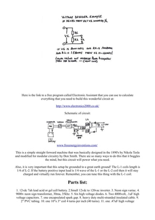
SlideShare a Scribd company logo
Monday, June 28, 2010
Don L Smith Device

Don L. Smith
Resonant Induction Energy Transfer
Device

Free Power!
www.freeenergyinventions.com/

WARNING! DANGER! HIGH VOLTAGE!
High voltage rules apply here!
Free Energy Device!
In this picture is everything you will need to make a self running power supply. The input is a 12vdc
7ah lead acid or gel cell battery (not shown). The input goes to a 12vdc to 120vac inverter of about
200 watts more or less, it is not critical as long as it can turn on the next part, the transformer. The
transformer is a 9000v, 30ma, 35khz neon sign transformer with two outputs that are rectified and
its output is controlled by the variac for neon signs after the inverter. The next thing you see is two
high voltage capacitors of .1uF 4000vdc. They are in parallel which makes .2uF 4000vdc. These are
the self healing type, though not critical as long as you keep the transformer adjusted to 4000 volts
or less. Don keeps it down around 2000 to 3000 volts.
The next part before the coils is the enclosed spark gap connected to the neon transformer ground
and the one end of the L-1 coil and the capacitors. Where the wire and the gap meet is also your
grounding lug for this part of the system. If you look carefully at the capacitors, you will see that
they are in parallel across the two L-1 coil wires (red) and the high voltage diodes are coming from
two different connections and meeting at the capacitors. Look carefully at the polarity of the diodes.
These diodes should be rated at least 2 times the output of the transformer.
The next part is the L-1 coil that takes the power that you have generated and sets how much you
are going to step it up. For example: If you have 2500 volts coming from the transformer and you
have 10 turns on your L-1 coil, then you divide 2500 by 10 and you get 250 volts to transfer to each
L-2 winding. So if you have 30 windings on your L-2 coil, then you will have stepped the voltage
up to 7500 volts. 60 windings = 15000 volts. 100 windings = 25000 volts and so on. Get it? So far
its basic Tesla stuff.
In this setup, the L-1 coil (the one going through the middle of the bigger coil) has 5 turns on a 2"
PVC tube with the connecting wires running through the inside of the tube. The wires for the L-1
coil are multi-stranded. This is an adjustable coil setup for tuning the coils as per Nikola Tesla's
design circa 1896. The L-2 coil is a Barker-Williamson 10" x 3" 40 turn tinned copper coil 10 or 12
Awg with 4 turns removed in the middle (or unwound for connections). This coil is 4 turns per inch
and costs about $100.00. You can make your own by wrapping your wire around a form for a lot
less! If you will notice, the L-2 coil is separated in the middle and then hooked together at the
grounding lug in the middle. This is for better control of the frequency and amperage....that's right, I
said AMPERAGE! At this stage of the game, this mother will kill you instantly so be careful! High
voltage rules apply here! Tesla definitely knew how to produce more than just sparks!
In the following Tesla diagrams, the top one is how to finish the circuit for high frequency power
and the bottom left is the coils in the device in this article. Notice in the bottom left the L-1 coil
inside the L-2 coil with the split coils and the center tap for amperage? Look like anything we are
building here?
If Tesla coil builders would just look and read what Tesla was really after and accomplished, they
would have a lot more than just sparks flying from their coils! They would have real usable power
in the kilowatt to megawatt range!
www.freeenergyinventions.com/
Ok, on with the picture. At this point the L-2 coil is connected in 3 places. The top +, the middle -,
the bottom +. Across the top + and the middle - is a .47 uF high voltage capacitor. You only need the
one because of the L-2 coil being hooked in series. The high voltage diodes are rectifying both top
and bottom positives giving you pulsed DC.
The capacitor bank (the gray ones on the right) are four 2000vdc 8uF oil filled caps in series NOT
parallel, giving this setup a continuous 8000 volts @ 20 amperes of power.
The trick to using this power from the capacitors output is to choke it down to the voltage for your
isolation transformer to use. This acts like a dam on a river and the pressure for your voltage is right
there just like a battery. Use a voltage divider rated for volts and amps at this point. Use an inverting
circuit after the voltage divider for true AC and 120 hertz frequency (60 up/60 down) to the
transformer. Remember, this mother can fry isolation transformers so be sure to have one rated at
least 30 amps. Ohms law and full amperage only comes into effect at the isolation transformer
circuit. The more you load it, the more amperage it produces.......just as Tesla said it would
do.........that's why it can fry transformers!
Here is the link to a free program called Electronic Assistant that you can use to calculate
everything that you need to build this wonderful circuit at:
http://www.electronics2000.co.uk/
Schematic of circuit:

www.freeenergyinventions.com/
This is a simple straight forward machine that was basically designed in the 1890's by Nikola Tesla
and modified for modular circuitry by Don Smith. There are so many ways to do this that it boggles
the mind, but this circuit will power what you need.
Also, it is very important that this setup be grounded to a great earth ground! The L-1 coils length is
1/4 of L-2. If the battery positive input lead is 1/4 wave of the L-1 or the L-2 coil then it will stay
charged and virtually run forever. Remember, you can tune this thing with the L-1 coil.

Parts list:
1. 12vdc 7ah lead acid or gel cell battery. 2.Small 12vdc to 120vac inverter. 3. Neon sign variac. 4.
9000v neon sign transformer, 30ma, 35khz. 5. Six high voltage diodes. 6. Two 4000volt, .1uF high
voltage capacitors. 7. one encapsulated spark gap. 8. heavy duty multi-stranded insulated cable. 9.
2" PVC tubing. 10. one 10"x 3" coil 4 turns per inch (40 turns). 11. one .47uF high voltage
capacitor. 12. four 2000vdc, oil filled, high voltage capacitors totaling 2uF_8000vdc. 13. Various
connectors and lugs. 14. High voltage cable for connection to the 8000vdc caps (auto ignition cable
comes to mind).
WARNING!!!
Build these projects at your own risk! We are not responsible for errors in the plans, diagrams, or
instructions and other people’s opinions on these projects! Some of these projects deal with very
high voltages!! If you are not familiar with high voltages/amps we recommend that you seek the
services of a qualified licensed professional to help you! High voltages can kill in an instant so be
safe and learn all that you can about high voltage safety before attempting these projects! This
website is for information/entertainment purposes only.
For more free energy devices and info go to:
Copywrite http://www.freeenergyinventions.com/
2010

More Related Content

What's hot

PDi Regenerative Acceleration Generator (ReGenX) 2013 Patent Disclosure
PDi Regenerative Acceleration Generator (ReGenX) 2013 Patent DisclosurePDi Regenerative Acceleration Generator (ReGenX) 2013 Patent Disclosure
PDi Regenerative Acceleration Generator (ReGenX) 2013 Patent Disclosure
Thane Heins
 
FINAL Potential Difference inc. Innovations Test Program with 13 Internationa...
FINAL Potential Difference inc. Innovations Test Program with 13 Internationa...FINAL Potential Difference inc. Innovations Test Program with 13 Internationa...
FINAL Potential Difference inc. Innovations Test Program with 13 Internationa...
Thane Heins
 
P di regenerative acceleration generator (re genx) 2013 patent disclosure
P di regenerative acceleration generator (re genx) 2013 patent disclosureP di regenerative acceleration generator (re genx) 2013 patent disclosure
P di regenerative acceleration generator (re genx) 2013 patent disclosure
Thane Heins
 

What's hot (20)

ReGenX Generator Prototypes for Advanced Energy Performance Testing and Valid...
ReGenX Generator Prototypes for Advanced Energy Performance Testing and Valid...ReGenX Generator Prototypes for Advanced Energy Performance Testing and Valid...
ReGenX Generator Prototypes for Advanced Energy Performance Testing and Valid...
 
EV WORLD Heins Effect Gaining Credibility
EV WORLD Heins Effect Gaining CredibilityEV WORLD Heins Effect Gaining Credibility
EV WORLD Heins Effect Gaining Credibility
 
PDi Regenerative Acceleration Generator (ReGenX) 2013 Patent Disclosure
PDi Regenerative Acceleration Generator (ReGenX) 2013 Patent DisclosurePDi Regenerative Acceleration Generator (ReGenX) 2013 Patent Disclosure
PDi Regenerative Acceleration Generator (ReGenX) 2013 Patent Disclosure
 
UN Ban on ChemTrail / Geo Engineering 2010
UN Ban on ChemTrail / Geo Engineering 2010UN Ban on ChemTrail / Geo Engineering 2010
UN Ban on ChemTrail / Geo Engineering 2010
 
Infinite Efficiency HILLCREST PETROLEUM AND DESIGN 1ST Potential Difference I...
Infinite Efficiency HILLCREST PETROLEUM AND DESIGN 1ST Potential Difference I...Infinite Efficiency HILLCREST PETROLEUM AND DESIGN 1ST Potential Difference I...
Infinite Efficiency HILLCREST PETROLEUM AND DESIGN 1ST Potential Difference I...
 
FINAL Potential Difference inc. Innovations Test Program with 13 Internationa...
FINAL Potential Difference inc. Innovations Test Program with 13 Internationa...FINAL Potential Difference inc. Innovations Test Program with 13 Internationa...
FINAL Potential Difference inc. Innovations Test Program with 13 Internationa...
 
Introduction to tesla_coil
Introduction to tesla_coilIntroduction to tesla_coil
Introduction to tesla_coil
 
Tesla Coil
Tesla Coil  Tesla Coil
Tesla Coil
 
Tesla coil
Tesla coilTesla coil
Tesla coil
 
High Frequency High Voltage AC Generation
High Frequency High Voltage AC Generation High Frequency High Voltage AC Generation
High Frequency High Voltage AC Generation
 
Chapter5
Chapter5Chapter5
Chapter5
 
LAW OF CREATION OF ENERGY.pdf
LAW OF CREATION OF ENERGY.pdfLAW OF CREATION OF ENERGY.pdf
LAW OF CREATION OF ENERGY.pdf
 
maximum power transform
maximum power transformmaximum power transform
maximum power transform
 
What is Transformer, Introduction to Transformers (Brief)
What is Transformer, Introduction to Transformers (Brief)  What is Transformer, Introduction to Transformers (Brief)
What is Transformer, Introduction to Transformers (Brief)
 
P di regenerative acceleration generator (re genx) 2013 patent disclosure
P di regenerative acceleration generator (re genx) 2013 patent disclosureP di regenerative acceleration generator (re genx) 2013 patent disclosure
P di regenerative acceleration generator (re genx) 2013 patent disclosure
 
2018 INFINITE EFFICIENCY ReGenX Generator, Bi-Toroid Transformer Tests Report...
2018 INFINITE EFFICIENCY ReGenX Generator, Bi-Toroid Transformer Tests Report...2018 INFINITE EFFICIENCY ReGenX Generator, Bi-Toroid Transformer Tests Report...
2018 INFINITE EFFICIENCY ReGenX Generator, Bi-Toroid Transformer Tests Report...
 
Wireless Electricity
Wireless ElectricityWireless Electricity
Wireless Electricity
 
THE FUTURE OF ELECTRIC POWER GENERATION 2.0 - for all generations...
THE FUTURE OF ELECTRIC POWER GENERATION 2.0 - for all generations...THE FUTURE OF ELECTRIC POWER GENERATION 2.0 - for all generations...
THE FUTURE OF ELECTRIC POWER GENERATION 2.0 - for all generations...
 
Chapter3
Chapter3Chapter3
Chapter3
 
CORRECTIONS FOR GEORGIA STATE UNIVERSITY HYPERPHYSICS
CORRECTIONS FOR GEORGIA STATE UNIVERSITY HYPERPHYSICSCORRECTIONS FOR GEORGIA STATE UNIVERSITY HYPERPHYSICS
CORRECTIONS FOR GEORGIA STATE UNIVERSITY HYPERPHYSICS
 

Similar to 2k w free energy device don smith

Circuito de inversor de 12vdc a 120 v ac
Circuito de inversor de 12vdc a 120 v acCircuito de inversor de 12vdc a 120 v ac
Circuito de inversor de 12vdc a 120 v ac
federicoblanco
 
1 100 transistorcircuits
1 100 transistorcircuits1 100 transistorcircuits
1 100 transistorcircuits
Alejandro Perez
 
UNIT -I per unit calculation,EQUIVALENT CIRCUIT
UNIT -I per unit calculation,EQUIVALENT CIRCUITUNIT -I per unit calculation,EQUIVALENT CIRCUIT
UNIT -I per unit calculation,EQUIVALENT CIRCUIT
Abinaya Saraswathy T
 
Electronics schematic circuits for the hobbyist
Electronics   schematic circuits for the hobbyistElectronics   schematic circuits for the hobbyist
Electronics schematic circuits for the hobbyist
Naga Tejaswi
 

Similar to 2k w free energy device don smith (20)

Circuito de inversor de 12vdc a 120 v ac
Circuito de inversor de 12vdc a 120 v acCircuito de inversor de 12vdc a 120 v ac
Circuito de inversor de 12vdc a 120 v ac
 
1 100 transistorcircuits
1 100 transistorcircuits1 100 transistorcircuits
1 100 transistorcircuits
 
30 led projects
30 led projects30 led projects
30 led projects
 
30 led projects
30 led projects30 led projects
30 led projects
 
UNIT -I per unit calculation,EQUIVALENT CIRCUIT
UNIT -I per unit calculation,EQUIVALENT CIRCUITUNIT -I per unit calculation,EQUIVALENT CIRCUIT
UNIT -I per unit calculation,EQUIVALENT CIRCUIT
 
30 led projects
30 led projects30 led projects
30 led projects
 
30 led projects
30 led projects30 led projects
30 led projects
 
30 led projects
30 led projects30 led projects
30 led projects
 
70 interesting circuits
70 interesting circuits70 interesting circuits
70 interesting circuits
 
Inverter ups
Inverter   upsInverter   ups
Inverter ups
 
30.led .projects
30.led .projects30.led .projects
30.led .projects
 
Randeep.pptx
Randeep.pptxRandeep.pptx
Randeep.pptx
 
project
projectproject
project
 
Electronics schematic circuits for the hobbyist
Electronics   schematic circuits for the hobbyistElectronics   schematic circuits for the hobbyist
Electronics schematic circuits for the hobbyist
 
Power supplies
Power suppliesPower supplies
Power supplies
 
DEEPAK PURE SINE WAVE INVERTER PRESENETATION
DEEPAK PURE SINE WAVE INVERTER PRESENETATIONDEEPAK PURE SINE WAVE INVERTER PRESENETATION
DEEPAK PURE SINE WAVE INVERTER PRESENETATION
 
AN ANALYSIS OF THE PURE SINE WAVE INVERTER
AN ANALYSIS OF THE PURE SINE WAVE INVERTERAN ANALYSIS OF THE PURE SINE WAVE INVERTER
AN ANALYSIS OF THE PURE SINE WAVE INVERTER
 
Automatic street light using ldr and relay
Automatic street light using ldr and relayAutomatic street light using ldr and relay
Automatic street light using ldr and relay
 
34866616-Relay.ppt
34866616-Relay.ppt34866616-Relay.ppt
34866616-Relay.ppt
 
elecabsbegin.pdf
elecabsbegin.pdfelecabsbegin.pdf
elecabsbegin.pdf
 

Recently uploaded

Recently uploaded (20)

How world-class product teams are winning in the AI era by CEO and Founder, P...
How world-class product teams are winning in the AI era by CEO and Founder, P...How world-class product teams are winning in the AI era by CEO and Founder, P...
How world-class product teams are winning in the AI era by CEO and Founder, P...
 
Designing Great Products: The Power of Design and Leadership by Chief Designe...
Designing Great Products: The Power of Design and Leadership by Chief Designe...Designing Great Products: The Power of Design and Leadership by Chief Designe...
Designing Great Products: The Power of Design and Leadership by Chief Designe...
 
Software Delivery At the Speed of AI: Inflectra Invests In AI-Powered Quality
Software Delivery At the Speed of AI: Inflectra Invests In AI-Powered QualitySoftware Delivery At the Speed of AI: Inflectra Invests In AI-Powered Quality
Software Delivery At the Speed of AI: Inflectra Invests In AI-Powered Quality
 
IOS-PENTESTING-BEGINNERS-PRACTICAL-GUIDE-.pptx
IOS-PENTESTING-BEGINNERS-PRACTICAL-GUIDE-.pptxIOS-PENTESTING-BEGINNERS-PRACTICAL-GUIDE-.pptx
IOS-PENTESTING-BEGINNERS-PRACTICAL-GUIDE-.pptx
 
UiPath Test Automation using UiPath Test Suite series, part 2
UiPath Test Automation using UiPath Test Suite series, part 2UiPath Test Automation using UiPath Test Suite series, part 2
UiPath Test Automation using UiPath Test Suite series, part 2
 
JMeter webinar - integration with InfluxDB and Grafana
JMeter webinar - integration with InfluxDB and GrafanaJMeter webinar - integration with InfluxDB and Grafana
JMeter webinar - integration with InfluxDB and Grafana
 
Agentic RAG What it is its types applications and implementation.pdf
Agentic RAG What it is its types applications and implementation.pdfAgentic RAG What it is its types applications and implementation.pdf
Agentic RAG What it is its types applications and implementation.pdf
 
"Impact of front-end architecture on development cost", Viktor Turskyi
"Impact of front-end architecture on development cost", Viktor Turskyi"Impact of front-end architecture on development cost", Viktor Turskyi
"Impact of front-end architecture on development cost", Viktor Turskyi
 
Exploring UiPath Orchestrator API: updates and limits in 2024 🚀
Exploring UiPath Orchestrator API: updates and limits in 2024 🚀Exploring UiPath Orchestrator API: updates and limits in 2024 🚀
Exploring UiPath Orchestrator API: updates and limits in 2024 🚀
 
Empowering NextGen Mobility via Large Action Model Infrastructure (LAMI): pav...
Empowering NextGen Mobility via Large Action Model Infrastructure (LAMI): pav...Empowering NextGen Mobility via Large Action Model Infrastructure (LAMI): pav...
Empowering NextGen Mobility via Large Action Model Infrastructure (LAMI): pav...
 
IoT Analytics Company Presentation May 2024
IoT Analytics Company Presentation May 2024IoT Analytics Company Presentation May 2024
IoT Analytics Company Presentation May 2024
 
Optimizing NoSQL Performance Through Observability
Optimizing NoSQL Performance Through ObservabilityOptimizing NoSQL Performance Through Observability
Optimizing NoSQL Performance Through Observability
 
Slack (or Teams) Automation for Bonterra Impact Management (fka Social Soluti...
Slack (or Teams) Automation for Bonterra Impact Management (fka Social Soluti...Slack (or Teams) Automation for Bonterra Impact Management (fka Social Soluti...
Slack (or Teams) Automation for Bonterra Impact Management (fka Social Soluti...
 
From Siloed Products to Connected Ecosystem: Building a Sustainable and Scala...
From Siloed Products to Connected Ecosystem: Building a Sustainable and Scala...From Siloed Products to Connected Ecosystem: Building a Sustainable and Scala...
From Siloed Products to Connected Ecosystem: Building a Sustainable and Scala...
 
WSO2CONMay2024OpenSourceConferenceDebrief.pptx
WSO2CONMay2024OpenSourceConferenceDebrief.pptxWSO2CONMay2024OpenSourceConferenceDebrief.pptx
WSO2CONMay2024OpenSourceConferenceDebrief.pptx
 
AI for Every Business: Unlocking Your Product's Universal Potential by VP of ...
AI for Every Business: Unlocking Your Product's Universal Potential by VP of ...AI for Every Business: Unlocking Your Product's Universal Potential by VP of ...
AI for Every Business: Unlocking Your Product's Universal Potential by VP of ...
 
To Graph or Not to Graph Knowledge Graph Architectures and LLMs
To Graph or Not to Graph Knowledge Graph Architectures and LLMsTo Graph or Not to Graph Knowledge Graph Architectures and LLMs
To Graph or Not to Graph Knowledge Graph Architectures and LLMs
 
UiPath Test Automation using UiPath Test Suite series, part 1
UiPath Test Automation using UiPath Test Suite series, part 1UiPath Test Automation using UiPath Test Suite series, part 1
UiPath Test Automation using UiPath Test Suite series, part 1
 
Introduction to Open Source RAG and RAG Evaluation
Introduction to Open Source RAG and RAG EvaluationIntroduction to Open Source RAG and RAG Evaluation
Introduction to Open Source RAG and RAG Evaluation
 
The architecture of Generative AI for enterprises.pdf
The architecture of Generative AI for enterprises.pdfThe architecture of Generative AI for enterprises.pdf
The architecture of Generative AI for enterprises.pdf
 

2k w free energy device don smith

  • 1. Monday, June 28, 2010 Don L Smith Device Don L. Smith Resonant Induction Energy Transfer Device Free Power! www.freeenergyinventions.com/ WARNING! DANGER! HIGH VOLTAGE! High voltage rules apply here! Free Energy Device! In this picture is everything you will need to make a self running power supply. The input is a 12vdc 7ah lead acid or gel cell battery (not shown). The input goes to a 12vdc to 120vac inverter of about
  • 2. 200 watts more or less, it is not critical as long as it can turn on the next part, the transformer. The transformer is a 9000v, 30ma, 35khz neon sign transformer with two outputs that are rectified and its output is controlled by the variac for neon signs after the inverter. The next thing you see is two high voltage capacitors of .1uF 4000vdc. They are in parallel which makes .2uF 4000vdc. These are the self healing type, though not critical as long as you keep the transformer adjusted to 4000 volts or less. Don keeps it down around 2000 to 3000 volts. The next part before the coils is the enclosed spark gap connected to the neon transformer ground and the one end of the L-1 coil and the capacitors. Where the wire and the gap meet is also your grounding lug for this part of the system. If you look carefully at the capacitors, you will see that they are in parallel across the two L-1 coil wires (red) and the high voltage diodes are coming from two different connections and meeting at the capacitors. Look carefully at the polarity of the diodes. These diodes should be rated at least 2 times the output of the transformer. The next part is the L-1 coil that takes the power that you have generated and sets how much you are going to step it up. For example: If you have 2500 volts coming from the transformer and you have 10 turns on your L-1 coil, then you divide 2500 by 10 and you get 250 volts to transfer to each L-2 winding. So if you have 30 windings on your L-2 coil, then you will have stepped the voltage up to 7500 volts. 60 windings = 15000 volts. 100 windings = 25000 volts and so on. Get it? So far its basic Tesla stuff. In this setup, the L-1 coil (the one going through the middle of the bigger coil) has 5 turns on a 2" PVC tube with the connecting wires running through the inside of the tube. The wires for the L-1 coil are multi-stranded. This is an adjustable coil setup for tuning the coils as per Nikola Tesla's design circa 1896. The L-2 coil is a Barker-Williamson 10" x 3" 40 turn tinned copper coil 10 or 12 Awg with 4 turns removed in the middle (or unwound for connections). This coil is 4 turns per inch and costs about $100.00. You can make your own by wrapping your wire around a form for a lot less! If you will notice, the L-2 coil is separated in the middle and then hooked together at the grounding lug in the middle. This is for better control of the frequency and amperage....that's right, I said AMPERAGE! At this stage of the game, this mother will kill you instantly so be careful! High voltage rules apply here! Tesla definitely knew how to produce more than just sparks! In the following Tesla diagrams, the top one is how to finish the circuit for high frequency power and the bottom left is the coils in the device in this article. Notice in the bottom left the L-1 coil inside the L-2 coil with the split coils and the center tap for amperage? Look like anything we are building here? If Tesla coil builders would just look and read what Tesla was really after and accomplished, they would have a lot more than just sparks flying from their coils! They would have real usable power in the kilowatt to megawatt range!
  • 3. www.freeenergyinventions.com/ Ok, on with the picture. At this point the L-2 coil is connected in 3 places. The top +, the middle -, the bottom +. Across the top + and the middle - is a .47 uF high voltage capacitor. You only need the one because of the L-2 coil being hooked in series. The high voltage diodes are rectifying both top and bottom positives giving you pulsed DC. The capacitor bank (the gray ones on the right) are four 2000vdc 8uF oil filled caps in series NOT parallel, giving this setup a continuous 8000 volts @ 20 amperes of power. The trick to using this power from the capacitors output is to choke it down to the voltage for your isolation transformer to use. This acts like a dam on a river and the pressure for your voltage is right there just like a battery. Use a voltage divider rated for volts and amps at this point. Use an inverting circuit after the voltage divider for true AC and 120 hertz frequency (60 up/60 down) to the transformer. Remember, this mother can fry isolation transformers so be sure to have one rated at least 30 amps. Ohms law and full amperage only comes into effect at the isolation transformer circuit. The more you load it, the more amperage it produces.......just as Tesla said it would do.........that's why it can fry transformers!
  • 4. Here is the link to a free program called Electronic Assistant that you can use to calculate everything that you need to build this wonderful circuit at: http://www.electronics2000.co.uk/ Schematic of circuit: www.freeenergyinventions.com/ This is a simple straight forward machine that was basically designed in the 1890's by Nikola Tesla and modified for modular circuitry by Don Smith. There are so many ways to do this that it boggles the mind, but this circuit will power what you need. Also, it is very important that this setup be grounded to a great earth ground! The L-1 coils length is 1/4 of L-2. If the battery positive input lead is 1/4 wave of the L-1 or the L-2 coil then it will stay charged and virtually run forever. Remember, you can tune this thing with the L-1 coil. Parts list: 1. 12vdc 7ah lead acid or gel cell battery. 2.Small 12vdc to 120vac inverter. 3. Neon sign variac. 4. 9000v neon sign transformer, 30ma, 35khz. 5. Six high voltage diodes. 6. Two 4000volt, .1uF high voltage capacitors. 7. one encapsulated spark gap. 8. heavy duty multi-stranded insulated cable. 9. 2" PVC tubing. 10. one 10"x 3" coil 4 turns per inch (40 turns). 11. one .47uF high voltage
  • 5. capacitor. 12. four 2000vdc, oil filled, high voltage capacitors totaling 2uF_8000vdc. 13. Various connectors and lugs. 14. High voltage cable for connection to the 8000vdc caps (auto ignition cable comes to mind). WARNING!!! Build these projects at your own risk! We are not responsible for errors in the plans, diagrams, or instructions and other people’s opinions on these projects! Some of these projects deal with very high voltages!! If you are not familiar with high voltages/amps we recommend that you seek the services of a qualified licensed professional to help you! High voltages can kill in an instant so be safe and learn all that you can about high voltage safety before attempting these projects! This website is for information/entertainment purposes only. For more free energy devices and info go to: Copywrite http://www.freeenergyinventions.com/ 2010