Abaqus Project
•
0 likes•1,513 views
The document describes analyzing a retaining ring to determine if it will yield under stress. A finite element analysis was conducted modeling the ring as a 2D shell with plane stress. Spring steel was initially used as the material but yielded under the expected stress. Beryllium copper was then selected, which did not yield. A mesh convergence study determined a seed size of 0.6 provided an accurate result without excess computation time. The analysis concluded beryllium copper was a suitable material and no design changes were needed.
Report
Share
Report
Share
Download to read offline

Recommended
Torque Arm Modeling, Simulation & Optimization using Finite Element Methods
Torque Arm Modeling, Simulation & Optimization using Finite Element MethodsRavishankar Venkatasubramanian
Designed a torque arm, with Multi Point Constraints applied to the center of the arm. The FEA software used for this purpose was ABAQUS. The analysis was performed two major element types: Triangular Elements and Quadrilateral Elements, with relatively equal number of nodes in each case and a convergence study was conducted. The aim of the project was to obtain the optimal design parameters of the torque arm by optimization (minimize weight).Fea 2 mark
This document provides a summary of the course ME 2353 – Finite Element Analysis including 20 two-mark questions and answers related to various topics in finite element analysis. The questions cover topics such as variational methods, weighted residual methods, finite element formulation, element types, boundary conditions, discretization, shape functions, element stiffness matrices, and applications to heat transfer and fluid mechanics.
FEA Analysis - Thin Plate
Final Project for the class of "Mechanics of Deformable Solids -
MECH 321, McGill University.
In the following project, FEA Analysis was performed using ABAQUS. The results were then recorded and analyzed for the purpose of investigating the behavior of of a thin plate under various loading and boundary conditions.
Unit 5 threaded joint
Basic types of screw fasteners, Bolts of uniform
strength, I.S.O. Metric screw threads, Bolts under
tension, eccentrically loaded bolted joint in shear,
Eccentric load perpendicular and parallel to axis of
bolt, Eccentric load on circular base, design of Turn
Buckle.
Recent Advances in Finite element methods
This document summarizes a study on using frequency response methods to identify structural damage in layered composite materials. It proposes a new vibration-based technique that uses changes in the frequency response functions (FRFs) of an undamaged structure compared to a damaged one. Most reported works are based on changes in modal parameters, but this new method detects damage through existence, localization and extent using frequency response function curvature. It aims to establish an online damage identification method for laminated composites to address needs for health monitoring of composite structures, as damage alters their dynamic characteristics.
12 transient analysis theory
- Transient dynamic analysis determines the time-varying response of a structure to general time-dependent loads. It accounts for inertia and damping effects.
- The basic equation of motion solved includes mass, damping, stiffness matrices, and a load vector that varies over time. At discrete time points, these equations are similar to static equilibrium equations.
- Proper modeling of loads, time steps, and initial conditions is important for an accurate transient analysis. Loads can be applied as discrete steps or gradually ramped over time.
Torsion test
SAIF ALDIN ALI MADIN
سيف الدين علي ماضي
S96aif@gmail.com
Torsion tesd
MECHANICS OF MATERIALS
The objective of this experiment is to study the linearly elastic behavior
of metallic material under a torsion test. Torsion test measures the
strength of any material against maximum twisting forces. During this
experiment, a failure testing is done to our testing material which is a
steel. This failure testing involves twisting the material until it breaks
which helps demonstrates how materials undergo during testing
condition by measuring the applied torque with respect to the angle of
twist, the shear modulus, shear stress
At the limit of proportionality. The shear modulus of elasticity G and
Poisson's Ratio are determined for the specimen using torsional stressstrain relationship from the data collected during the experiment. The
fraction surface of our material at the end of the experiment is used to
stablish characteristics of the material,
Composite Forming in Ls Dyna.pptx
This document discusses using LS-DYNA software to simulate the thermoforming process. It introduces the geometry and finite element model created in HyperMesh and LS-Prepost. Shell elements are used to model the thin structures. Material models are defined for the rigid tools and deformable fabric. The forming process is defined through contact definitions, movement constraints, loading, time steps and other simulation settings. Results of the fabric draping simulation are compared to previous work and a parametric study is performed on the effect of blankholder force. Future work is proposed to further validate and expand on the thermoforming process simulations.
Tensile testing experiment
Tensile testing is used to determine the strength and ductility of materials. A specimen is placed in grips and pulled apart under increasing tensile force while measuring elongation. The resulting stress-strain curve provides properties like yield strength, tensile strength, and Young's modulus. Tensile tests are important for engineering design and quality control by ensuring materials can withstand expected loads and comparing new materials. Common applications include testing aircraft components, bolts, and other loaded structures.
Lec 2 compression test
This document summarizes a lecture on compression testing. It discusses how compression tests are used to determine material properties like compressive strength and modulus of elasticity. The test involves placing a sample in a universal testing machine and applying a compressive load until failure. Common applications include the aerospace, automotive, and construction industries. While easier than tension tests, compression tests can be impacted by friction, eccentric loading, and buckling of the sample. The document outlines best practices for sample geometry and preparation to minimize these issues and get accurate results.
Solucion semana 16
The document contains 3 engineering problems involving column buckling calculations. Problem 1 asks to determine the allowable centric load for a welded column with a given factor of safety. Problem 2 asks to determine the factor of safety for a loaded channel member buckling in plane. Problem 3 asks to determine the maximum dimensions for support locations that result in the largest allowable load for an aluminum strut, and then calculate the allowable load value.
Design and Analysis of a Single Plate Clutch Assembly
- The document describes the design and analysis of a single plate clutch assembly for a pickup truck.
- Key components of the clutch include the flywheel, pressure plate, friction plate, and springs. Materials are selected based on requirements.
- Calculations are shown for determining the inner diameter of the friction plate, required spring force, torque capacity, power capacity, and dimensions of other components.
- AutoCAD is used to create drawings based on the calculations. The final design specifications including torque capacity, power capacity, diameters, number of springs, and service factor are provided.
Machine design lab manual
This document provides information on designing a connecting rod, including:
1. The connecting rod transmits force from the piston to the crankpin. Stresses on it include gas pressure, inertia, friction, and its own inertia.
2. Formulas are given to calculate the load due to gas pressure and piston inertia, friction forces, and the connecting rod's inertia forces.
3. Maximum bending moment and stress on the connecting rod are calculated. A buckling load formula is also provided. The connecting rod design must withstand the buckling load with an appropriate factor of safety.
Wire ropes
Wire ropes are made of strands of twisted steel wires wrapped around a core. They are used to transmit power over long distances in applications like elevators, cranes, and bridges. Wire ropes have advantages like being lighter, more reliable, and durable. They are classified based on the direction of twist of the wires and strands. Design considerations for wire ropes include selecting the type based on application, calculating design load and rope diameter, and ensuring stresses do not exceed the rope's ultimate strength. Sample problems demonstrate designing a wire rope for a mine hoist and selecting a rope to lift debris from a well.
FEA good practices presentation
This document provides an overview of good practices in finite element analysis (FEA). It discusses various topics including the FEA process, analysis types, element types, mesh quality, and validation. The modern design process utilizes optimization and virtual testing with FEA earlier in the process compared to the traditional design-build-test approach. A variety of linear and nonlinear analysis types are described such as static, dynamic, and buckling analyses. The document emphasizes the importance of validation, quality assurance, and maintaining proper documentation of the FEA process.
3. v belt and sample problem
This document discusses the design and selection of V-belt drives. It describes the different types of V-belts and provides details on their cross-section. The advantages of V-belt drives are listed, such as smooth operation, ability to transmit power around corners, long service life, and acting as a safety fuse. The procedure for selecting a V-belt drive includes choosing the belt section, standard pulleys, center distance, nominal pitch length, modification factors, maximum power capacity, number of belts, and pulley dimensions. An example problem is provided to demonstrate the selection process. Key differences between flat belt drives and V-belt drives are also outlined.
machine-design-problems
The document describes three engineering design problems involving the creation of assistive devices for quadriplegic individuals. For each problem, it provides a goal statement and lists at least 12 task specifications that would need to be considered to solve the problem. It then asks students to suggest three concepts and provide sketches for each concept to achieve the stated goal. The problems involve designing a mouse trap, a bowling assist device, and an automated page turner.
FEA Project-Plate Analysis
This document describes a finite element analysis of a thin plate with different hole geometries under tension. Circular, elliptical, and rectangular holes were modeled in the center of a plate. Theoretical stress concentrations were calculated and compared to FE model results. A convergence study determined an optimal mesh size of 25mm. Results from full and quarter plate models showed good agreement, with stress value deviations within 2% and displacement deviations within 1%.
Tutor abaqus 2.
This document provides instructions for completing a tutorial to create and analyze a simple model of a cantilever beam using ABAQUS/CAE. It describes starting ABAQUS/CAE, understanding the different modules for building the model, creating parts, materials, and meshes, applying loads and boundary conditions, submitting an analysis job, and viewing the results. The goal is to guide users through the basic modeling process in ABAQUS/CAE.
Gear and Screw measurement
Screw Thread measurement: Two wire
Screw Thread measurement: Three wire
Screw Thread measurement: Floating Carriage
Gear measurement: Gear tooth comparator
Gear measurement: Master Gear
Gear measurement: Using Rollers and Parkinson Gear Tester
Special measuring Equipments: Principles of measurement using Tool Maker’s microscope,
Special measuring Equipments: Principles of measurement using Profile Projector
Special measuring Equipments: Principles of measurement using 3D CMM
TRUSS ANALYSIS (TERM PAPER REPORT)
This document provides an introduction and overview of truss analysis. It defines a truss and describes the key assumptions made in truss analysis, including that loads act only at joints and member weights are negligible. It then describes the two main methods for truss analysis - the method of joints and method of sections. An example problem is worked through for each method to demonstrate how to determine the forces in each truss member.
How to use Vernier Caliper and how to take measurement from it.
This document describes how to use a Vernier caliper to take measurements. It defines true value as the average of infinite measurements with zero average deviation, while measured value is the approximated true value found from multiple readings. Static error is the difference between measured and true values. The procedure explains how to check for zero error, take main and Vernier scale readings, calculate the measurement using least count, and record results from different specimens. Precautions include cleaning the caliper and items measured to minimize errors and get accurate readings.
Tensile test
Tensile test research and accurate data for academics and professional engineers. Engineers use tensile tests to solve most fracture problems.
Press fit force calculation
Method to calculate the press fit force for device as servo presses, hydraulic presses and other devices used to fit componets in automated assembly line
Lab report engineering materials lab - tensile test
This is my Lab Report of Tensile Test when I was conducting engineering material lab in Sampoerna University. Feel free to download for a reference.
I know it is not a good report, but I hope this share might help you to find something you need.
Thank you.
Band brake
The document discusses the parts, efficiency, and advantages and disadvantages of band brakes. It notes that band brakes have a simple design that is easy to maintain and can work properly for years without breakdowns, as long as the drum is kept clean and free from rust. Advantages include simplicity while disadvantages are not outlined. The document primarily focuses on sharing an email address and does not provide much useful information.
ABAQUS Lecture Part II
This document provides an overview of using ABAQUS CAE software to model and analyze a 2D plane stress problem of a cantilever beam subjected to a pressure load. It describes the basic ABAQUS CAE modules for creating parts, assigning materials properties, assembling parts, applying loads and boundary conditions, meshing, submitting the job for analysis, and visualizing results. It then walks through creating and analyzing a simple 2D plane stress model of a cantilever beam as a tutorial for learning the basic ABAQUS CAE workflow and modules.
Abaqus tutorial
This document provides an introduction to using Abaqus finite element analysis software. It outlines the key features of Abaqus including its extensive library of elements to model various geometries and materials, and its capabilities for static and dynamic linear and nonlinear analysis. The document then presents example tutorials for creating models of a truss, 2D plate, and 3D solid to demonstrate how to use Abaqus/CAE for finite element modeling, applying loads and boundary conditions, meshing, running analyses, and post-processing results. It is intended as a quick introduction to the software for a course on finite elements at Rensselaer Polytechnic Institute.
tiffany & co.
Tiffany & Co. sells various pieces of silver jewelry including necklaces, bracelets, earrings, and rings as well as lock charms and watches decorated with their signature hearts and stars designs. Diamonds are also available from the luxury brand.
More Related Content
What's hot
Composite Forming in Ls Dyna.pptx
This document discusses using LS-DYNA software to simulate the thermoforming process. It introduces the geometry and finite element model created in HyperMesh and LS-Prepost. Shell elements are used to model the thin structures. Material models are defined for the rigid tools and deformable fabric. The forming process is defined through contact definitions, movement constraints, loading, time steps and other simulation settings. Results of the fabric draping simulation are compared to previous work and a parametric study is performed on the effect of blankholder force. Future work is proposed to further validate and expand on the thermoforming process simulations.
Tensile testing experiment
Tensile testing is used to determine the strength and ductility of materials. A specimen is placed in grips and pulled apart under increasing tensile force while measuring elongation. The resulting stress-strain curve provides properties like yield strength, tensile strength, and Young's modulus. Tensile tests are important for engineering design and quality control by ensuring materials can withstand expected loads and comparing new materials. Common applications include testing aircraft components, bolts, and other loaded structures.
Lec 2 compression test
This document summarizes a lecture on compression testing. It discusses how compression tests are used to determine material properties like compressive strength and modulus of elasticity. The test involves placing a sample in a universal testing machine and applying a compressive load until failure. Common applications include the aerospace, automotive, and construction industries. While easier than tension tests, compression tests can be impacted by friction, eccentric loading, and buckling of the sample. The document outlines best practices for sample geometry and preparation to minimize these issues and get accurate results.
Solucion semana 16
The document contains 3 engineering problems involving column buckling calculations. Problem 1 asks to determine the allowable centric load for a welded column with a given factor of safety. Problem 2 asks to determine the factor of safety for a loaded channel member buckling in plane. Problem 3 asks to determine the maximum dimensions for support locations that result in the largest allowable load for an aluminum strut, and then calculate the allowable load value.
Design and Analysis of a Single Plate Clutch Assembly
- The document describes the design and analysis of a single plate clutch assembly for a pickup truck.
- Key components of the clutch include the flywheel, pressure plate, friction plate, and springs. Materials are selected based on requirements.
- Calculations are shown for determining the inner diameter of the friction plate, required spring force, torque capacity, power capacity, and dimensions of other components.
- AutoCAD is used to create drawings based on the calculations. The final design specifications including torque capacity, power capacity, diameters, number of springs, and service factor are provided.
Machine design lab manual
This document provides information on designing a connecting rod, including:
1. The connecting rod transmits force from the piston to the crankpin. Stresses on it include gas pressure, inertia, friction, and its own inertia.
2. Formulas are given to calculate the load due to gas pressure and piston inertia, friction forces, and the connecting rod's inertia forces.
3. Maximum bending moment and stress on the connecting rod are calculated. A buckling load formula is also provided. The connecting rod design must withstand the buckling load with an appropriate factor of safety.
Wire ropes
Wire ropes are made of strands of twisted steel wires wrapped around a core. They are used to transmit power over long distances in applications like elevators, cranes, and bridges. Wire ropes have advantages like being lighter, more reliable, and durable. They are classified based on the direction of twist of the wires and strands. Design considerations for wire ropes include selecting the type based on application, calculating design load and rope diameter, and ensuring stresses do not exceed the rope's ultimate strength. Sample problems demonstrate designing a wire rope for a mine hoist and selecting a rope to lift debris from a well.
FEA good practices presentation
This document provides an overview of good practices in finite element analysis (FEA). It discusses various topics including the FEA process, analysis types, element types, mesh quality, and validation. The modern design process utilizes optimization and virtual testing with FEA earlier in the process compared to the traditional design-build-test approach. A variety of linear and nonlinear analysis types are described such as static, dynamic, and buckling analyses. The document emphasizes the importance of validation, quality assurance, and maintaining proper documentation of the FEA process.
3. v belt and sample problem
This document discusses the design and selection of V-belt drives. It describes the different types of V-belts and provides details on their cross-section. The advantages of V-belt drives are listed, such as smooth operation, ability to transmit power around corners, long service life, and acting as a safety fuse. The procedure for selecting a V-belt drive includes choosing the belt section, standard pulleys, center distance, nominal pitch length, modification factors, maximum power capacity, number of belts, and pulley dimensions. An example problem is provided to demonstrate the selection process. Key differences between flat belt drives and V-belt drives are also outlined.
machine-design-problems
The document describes three engineering design problems involving the creation of assistive devices for quadriplegic individuals. For each problem, it provides a goal statement and lists at least 12 task specifications that would need to be considered to solve the problem. It then asks students to suggest three concepts and provide sketches for each concept to achieve the stated goal. The problems involve designing a mouse trap, a bowling assist device, and an automated page turner.
FEA Project-Plate Analysis
This document describes a finite element analysis of a thin plate with different hole geometries under tension. Circular, elliptical, and rectangular holes were modeled in the center of a plate. Theoretical stress concentrations were calculated and compared to FE model results. A convergence study determined an optimal mesh size of 25mm. Results from full and quarter plate models showed good agreement, with stress value deviations within 2% and displacement deviations within 1%.
Tutor abaqus 2.
This document provides instructions for completing a tutorial to create and analyze a simple model of a cantilever beam using ABAQUS/CAE. It describes starting ABAQUS/CAE, understanding the different modules for building the model, creating parts, materials, and meshes, applying loads and boundary conditions, submitting an analysis job, and viewing the results. The goal is to guide users through the basic modeling process in ABAQUS/CAE.
Gear and Screw measurement
Screw Thread measurement: Two wire
Screw Thread measurement: Three wire
Screw Thread measurement: Floating Carriage
Gear measurement: Gear tooth comparator
Gear measurement: Master Gear
Gear measurement: Using Rollers and Parkinson Gear Tester
Special measuring Equipments: Principles of measurement using Tool Maker’s microscope,
Special measuring Equipments: Principles of measurement using Profile Projector
Special measuring Equipments: Principles of measurement using 3D CMM
TRUSS ANALYSIS (TERM PAPER REPORT)
This document provides an introduction and overview of truss analysis. It defines a truss and describes the key assumptions made in truss analysis, including that loads act only at joints and member weights are negligible. It then describes the two main methods for truss analysis - the method of joints and method of sections. An example problem is worked through for each method to demonstrate how to determine the forces in each truss member.
How to use Vernier Caliper and how to take measurement from it.
This document describes how to use a Vernier caliper to take measurements. It defines true value as the average of infinite measurements with zero average deviation, while measured value is the approximated true value found from multiple readings. Static error is the difference between measured and true values. The procedure explains how to check for zero error, take main and Vernier scale readings, calculate the measurement using least count, and record results from different specimens. Precautions include cleaning the caliper and items measured to minimize errors and get accurate readings.
Tensile test
Tensile test research and accurate data for academics and professional engineers. Engineers use tensile tests to solve most fracture problems.
Press fit force calculation
Method to calculate the press fit force for device as servo presses, hydraulic presses and other devices used to fit componets in automated assembly line
Lab report engineering materials lab - tensile test
This is my Lab Report of Tensile Test when I was conducting engineering material lab in Sampoerna University. Feel free to download for a reference.
I know it is not a good report, but I hope this share might help you to find something you need.
Thank you.
Band brake
The document discusses the parts, efficiency, and advantages and disadvantages of band brakes. It notes that band brakes have a simple design that is easy to maintain and can work properly for years without breakdowns, as long as the drum is kept clean and free from rust. Advantages include simplicity while disadvantages are not outlined. The document primarily focuses on sharing an email address and does not provide much useful information.
ABAQUS Lecture Part II
This document provides an overview of using ABAQUS CAE software to model and analyze a 2D plane stress problem of a cantilever beam subjected to a pressure load. It describes the basic ABAQUS CAE modules for creating parts, assigning materials properties, assembling parts, applying loads and boundary conditions, meshing, submitting the job for analysis, and visualizing results. It then walks through creating and analyzing a simple 2D plane stress model of a cantilever beam as a tutorial for learning the basic ABAQUS CAE workflow and modules.
What's hot (20)
Design and Analysis of a Single Plate Clutch Assembly
Design and Analysis of a Single Plate Clutch Assembly
How to use Vernier Caliper and how to take measurement from it.
How to use Vernier Caliper and how to take measurement from it.
Lab report engineering materials lab - tensile test
Lab report engineering materials lab - tensile test
Viewers also liked
Abaqus tutorial
This document provides an introduction to using Abaqus finite element analysis software. It outlines the key features of Abaqus including its extensive library of elements to model various geometries and materials, and its capabilities for static and dynamic linear and nonlinear analysis. The document then presents example tutorials for creating models of a truss, 2D plate, and 3D solid to demonstrate how to use Abaqus/CAE for finite element modeling, applying loads and boundary conditions, meshing, running analyses, and post-processing results. It is intended as a quick introduction to the software for a course on finite elements at Rensselaer Polytechnic Institute.
tiffany & co.
Tiffany & Co. sells various pieces of silver jewelry including necklaces, bracelets, earrings, and rings as well as lock charms and watches decorated with their signature hearts and stars designs. Diamonds are also available from the luxury brand.
Abaqus tutorial
This document provides instructions for creating a finite element model and analysis in ABAQUS. It describes how to generate nodes and elements, define section properties, apply loads and boundary conditions, and output results for a nonlinear beam-column model with spring, damper, and user-defined elements. Key steps include mesh generation, defining nonlinear beam properties, applying gravity loads, performing a displacement-controlled pushover analysis, and conducting a time-history dynamic analysis under base excitation. Variables for the user-defined element subroutine are also outlined.
ABAQUS Lecture Part I
This document provides an overview of ABAQUS finite element analysis software. It discusses the different ABAQUS products, why ABAQUS is useful to learn, documentation resources, and how to build simple models. It also gives examples of modeling a cantilever beam and truss structure, showing the model definition, material properties, loads, and desired output.
Fasteners & fastening
This document discusses different types of fasteners and fastening methods. It describes threaded fasteners like bolts, screws, and nuts. It defines screw thread terminology and profiles of common thread types. It explains characteristics of bolts and nuts like chamfering, washer facing, and counter-sinking. Methods for drawing hexagonal and square head bolts and nuts are also presented. The document provides details on different threaded fastener components and their uses to fasten and join parts in machines and structures.
Abaqus modelling and_analysis
This Presentation has been created for MAE577 course. The topic of the presentation is "Abaqus Modeling techniques and Analysis'
Introduction to Abaqus FEA (tutorial)
This document provides instructions for using Abaqus FEA software to analyze a plate with a hole. The summary includes:
1. Define the geometry of constituent parts including a rectangular plate and hole.
2. Create material definitions, apply properties, and assign sections.
3. Assign loads, boundary conditions, and interactions.
4. Specify analysis steps such as applying loads and constraints.
5. Submit the analysis and monitor the results.
Viewers also liked (8)
Similar to Abaqus Project
Modeling and fem analysis of knuckle joint
This report presents the structural analysis of knuckle joint using finite element analysis. The analysis considered the fracture failure of the structure from a loading of 70 kN axial load. It was found that the structure has a factor of safety of 2 for this loading and failure mode. The structure is therefore satisfactory for the desire design condition. The model is done with solid work and imported into Ansys. The FEM analysis had done with different mesh type and compared the result obtained. Further study in this direction can made by using various diameter of the pin, choosing the different material and the capacity to withstand load.
MMAE 594_Report
1. The document describes a study that used finite element analysis to simulate the burst pressure of a vibration welded plastic vessel and determine the yield stress at the weld bead.
2. An experimental hydrostatic pressure test showed rupture occurred at the weld bead, so the goal was to model this and obtain the stress at the weld bead.
3. Various meshing techniques were tested in the FEA software ABAQUS to find the best correlation with experimental data, including different element types, sizes, and modeling of the weld bead. The results showed second order elements with two layers of dragged elements for the weld bead membrane provided the most accurate stresses at the weld bead.
Interference fit simulation on pin joint by using ansys
Abstract The present study objective is to investigate the effect of interference fit range of contact stress distribution of centrally holed plate, this will be used in riveted joints, permanent fasteners joints applications. There are a lot of studies are carried out related to the effect of interference fit to enhance the life of components, however, present work aims to study the effect of contact stress distribution of a interference fit by considering properties of Stainless Steel and Aluminium alloy. Keywords: Interference Fit, Stainless Steel and Aluminium Alloy Materials, Contact Stresses and ANSYS
IRJET- Parametric Optimization of Flexure Bearing using FEA
This document summarizes a study that used finite element analysis to optimize the design of a three-arm spiral flexure bearing. The researchers used Taguchi's design of experiments approach to determine the most important design parameters for minimizing stress in the bearing. They analyzed thickness, slot width, shape factor, and sweep angle at different levels. The analysis found that thickness had the greatest impact on stress, followed by sweep angle, with shape factor and slot width being less significant. This provided guidance on how to prioritize design parameters to maximize the bearing's life.
Design of Pressure Vessel using ASME Codes and a Comparative Analysis using FEA
This document summarizes a research paper that analyzes the design of a pressure vessel using ASME codes and finite element analysis (FEA). The researchers first size the pressure vessel components like the shell and dome according to ASME code equations. They then build a finite element model of the vessel and apply internal pressure to analyze stresses. Von Mises, hoop, and radial stresses are found to be below allowable limits. The researchers then optimize the vessel design around high-stress areas like welds through additional FEA simulations. In summary, the document presents a process of pressure vessel design verification using both ASME codes and finite element analysis and optimization.
Composite Forming in Ls Dyna.pptx
This document discusses using LS-DYNA software to simulate the thermoforming process. It introduces the geometry and finite element model created in HyperMesh and LS-Prepost. Shell elements are used to model the thin structures. Material models are defined for the rigid tools and deformable fabric. The forming process is defined through contact definitions, prescribed motion of the punch, and blank holder force. Results of the fiber orientation and shear angle distribution are compared to previous work. Parameters like yarn thickness and friction could not be exactly determined and may contribute to differences in results.
MAE235_project
The document summarizes a study that used finite element analysis in Abaqus to calculate the von Mises stress in an aluminum membrane under thermal loading. Meshes with different element sizes were used and Richardson extrapolation was performed to estimate the true von Mises stress as the element size approaches zero. The highest stress was found at the center of the circular arc edge. Extrapolation estimated the true stress here to be 82.7885 MPa with a convergence rate of 0.957.
feanalysis
The document describes the design of a nitrogen storage tank including thickness calculations for the cylindrical tank walls and end caps to withstand an internal pressure of 110 psi. An initial plate model was used to determine optimal thicknesses, then an axisymmetric model was created to better model stress concentrations, particularly around welds. The maximum stresses found from both models were below the allowable stresses for the 6061-T6 aluminum material.
Sieve Analysis of Fine & Coarse Aggregate | Jameel Academy
This report summarizes the results of a sieve analysis test performed on samples of fine and coarse aggregates. Sieve analysis was used to determine the particle size distribution of each aggregate by separating particles via sieves with decreasing size openings. For the fine aggregate, the average size was found to be 0.6mm. For the coarse aggregate, the maximum size was found to be 13.2mm. While the calculations and procedures appeared to be performed correctly, the results did not fully meet specification limits, indicating the aggregates may not be suitable for the intended construction purpose without further processing or testing.
Determination of stress using Hypermesh-Optistruct
Project 1 involves using HyperMesh to determine stresses on plates with round and square holes under tensile stress. The plate dimensions are 500mm x 500mm with a 25mm round hole and 25mm x 25mm square hole. A 1kN/m2 tensile stress is applied. Geometry, material properties, meshing, loads, and analysis are created in HyperMesh. For the round hole, maximum principal stress is 2.198x10⁻³ MPa and maximum displacement is 1.163x10⁻⁶ mm. For the square hole, maximum principal stress is 1.68x10⁻³ MPa and maximum displacement is 1.148x10⁻⁶ mm. Stresses are highest at the hole edges
PMX Bend Formability Study
This document summarizes a bend formability study of copper alloys conducted by Samir Khoda. Samples of different alloys were bent longitudinally and transversely to evaluate their formability. Testing found that formability decreases with smaller bend radii and wider widths due to increased stress. Results showed minimum and recommended bend radii and width combinations to avoid cracking. The data helps customers design with the alloys by understanding their limits to prevent breakage.
FEM_Modeling_Project_Evaluation of a Steel Pulley and Shaft Design
The document summarizes a finite element analysis (FEA) project evaluating the design of a steel pulley and shaft system. The initial FEA model found unrealistic stress concentrations and displacements due to invalid boundary conditions. The boundary conditions were customized and additional analyses were run with fillet radii of 1-5 mm added to reduce stress. Increasing the shaft diameter from 25mm to 30mm further reduced stress. The maximum stress was plotted against degrees of freedom for each model, with the 5mm fillet radius and 30mm shaft diameter model exhibiting the lowest stress of around 75MPa.
A Comparative Analysis of Structure of Machine Tool Component using Fuzzy Logic
This document presents a comparative analysis of using fuzzy logic versus conventional methods to design the structure of a machine tool component, specifically a lathe bed. It describes using both an I-section and box section for the bed design and calculating stresses using conventional trial and error methods. It then applies fuzzy logic by representing key design parameters like moment of inertia as fuzzy sets and calculating alpha cuts to determine optimal values that satisfy design requirements like limiting maximum stress. The results show that an I-section bed design optimized with fuzzy logic has lower stress values than a box section, demonstrating the advantages of the fuzzy logic approach over conventional trial and error methods.
G42063336
International Journal of Engineering Research and Applications (IJERA) is an open access online peer reviewed international journal that publishes research and review articles in the fields of Computer Science, Neural Networks, Electrical Engineering, Software Engineering, Information Technology, Mechanical Engineering, Chemical Engineering, Plastic Engineering, Food Technology, Textile Engineering, Nano Technology & science, Power Electronics, Electronics & Communication Engineering, Computational mathematics, Image processing, Civil Engineering, Structural Engineering, Environmental Engineering, VLSI Testing & Low Power VLSI Design etc.
finalreportedit.docx
The document summarizes a student design project to reduce stress and twist in a swept forward aircraft wing. The students analyzed straight and swept wing models to compare displacement and stress. They used MATLAB to calculate spar locations that increased torsional rigidity in a hollow wing. Models with two or three spars were then analyzed in ANSYS. A 27 Newton lifting force was applied based on lift coefficient calculations. Tables compare results of different spar arrangements and thicknesses, identifying a three-spar design with 0.025, 0.01, and 0.01 cm thicknesses as providing the least twist and stress. Increasing the front spar thickness further reduced twist but increased stress due to added weight and bending moment.
Die casting
This document discusses methods for determining the optimal number of cavities for a die casting machine. It outlines formulas to calculate the costs of die casting processing, trimming, and using multiple cavities. The total cost is calculated as the sum of these costs plus alloy costs. The most economical number of cavities balances the lowest per-part processing costs from more cavities with the higher costs of additional cavity dies and trims. Physical constraints like clamping force and shot volume may further limit the maximum number of cavities.
Garage Door Opener Individual Project
The document provides details on the design of a garage door opener including:
1. Design requirements including ensuring the spring fits within tolerance and the button protrudes enough to activate sensors.
2. Calculations to determine minimum displacement and force requirements.
3. Solidworks models created of the button and holder components.
4. Abaqus FEA analysis performed to evaluate stress levels and improve designs by reducing fillets and increasing thickness.
5. A heat transfer analysis of the holder box using Aluminum 7075 properties to evaluate the temperature distribution.
Modeling and Analysis of Bracket Assembly in Aerospace Industry
This document discusses the modeling and analysis of a bracket assembly used in the aerospace industry. The bracket assembly consists of a circular plate with nine lugs for mounting three different sized tanks. The individual components are modeled in NX CAD software and assembled. A finite element analysis is performed in ANSYS to analyze stresses on the assembly under pressure loads from the tanks. The analysis is conducted for the assembly made of aluminum alloy and three composite materials. The results show the von Mises stresses are below yield strengths in all cases, indicating the assembly design is safe for the applied loads.
Modeling and Analysis of Bracket Assembly in Aerospace Industry
This project deals with the Model and static Analysis of Bracket assembly used in Aerospace Industry. This bracket assembly is used for placing components for various purposes like carrying fuel and air. The mounting bracket assembly consists of a circular plate with nine lugs for which three different tanks are mounted. The individual components i.e., circular plate, lugs etc are modeled and assembled through NX-CAD Software.The loads are transferred by the tanks to the bracket are considered as pressure loads. To reveal the stresses induced due to pressure loads, Finite Element (FE) Analysis is performed with the help of ANSYS. Then the occurrence of max stress is found and factor of safety is calculated. This project provides a methodology for analysis of an assembly consisting of components made of composite materials and metal components.
30120130405010
This document discusses the design, analysis, and optimization of body flanges and cover flanges for steam condensers used in thermal power plants using finite element analysis. The researchers modeled flanges based on ASME code dimensions and analyzed stress levels, validating results against analytical calculations. Additional stiffeners were added through optimization, reducing flange thicknesses from 102mm to 90mm for the body flange and 60mm to 48mm for the cover flange while maintaining stress below allowable limits. Finite element analysis was found to overcome limitations of analytical methods and determine optimal flange dimensions within safety factors.
Similar to Abaqus Project (20)
Interference fit simulation on pin joint by using ansys
Interference fit simulation on pin joint by using ansys
IRJET- Parametric Optimization of Flexure Bearing using FEA
IRJET- Parametric Optimization of Flexure Bearing using FEA
Design of Pressure Vessel using ASME Codes and a Comparative Analysis using FEA
Design of Pressure Vessel using ASME Codes and a Comparative Analysis using FEA
Sieve Analysis of Fine & Coarse Aggregate | Jameel Academy
Sieve Analysis of Fine & Coarse Aggregate | Jameel Academy
Determination of stress using Hypermesh-Optistruct
Determination of stress using Hypermesh-Optistruct
FEM_Modeling_Project_Evaluation of a Steel Pulley and Shaft Design
FEM_Modeling_Project_Evaluation of a Steel Pulley and Shaft Design
A Comparative Analysis of Structure of Machine Tool Component using Fuzzy Logic
A Comparative Analysis of Structure of Machine Tool Component using Fuzzy Logic
Modeling and Analysis of Bracket Assembly in Aerospace Industry
Modeling and Analysis of Bracket Assembly in Aerospace Industry
Modeling and Analysis of Bracket Assembly in Aerospace Industry
Modeling and Analysis of Bracket Assembly in Aerospace Industry
Abaqus Project
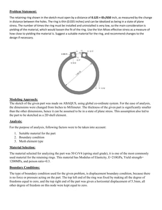
- 1. Problem Statement: The retaining ring shown in the sketch must open by a distance of 0.125 + ID1/650 inch, as measured by the change in distance between the holes. The ring is thin (0.035 inches) and can be idealized as being in a state of plane stress. The number of times the ring must be installed and uninstalled is very low, so the main consideration is yielding of the material, which would loosen the fit of the ring. Use the Von Mises effective stress as a measure of how close to yielding the material is. Suggest a suitable material for the ring, and recommend changes to the design if necessary. Modeling Approach: The sketch of the given part was made on ABAQUS, using global co-ordinate system. For the ease of analysis, the dimensions were changed from Inches to Millimeter. The thickness of the given part is significantly smaller than the other dimensions, hence it can be assumed to be in a state of plane stress. This assumption also led to the part to be sketched as a 2D shell element. Analysis: For the purpose of analysis, following factors were to be taken into account: 1. Suitable material for the part 2. Boundary condition 3. Mesh element type Material Selection: The material selected for analyzing the part was 50 CrV4 (spring steel grade), it is one of the most commonly used material for the retaining rings. This material has Modulus of Elasticity, E=210GPa, Yield strength= 1200MPa, and poison ratio=0.3. Boundary Conditions: The type of boundary condition used for the given problem, is displacement boundary condition, because there is no force or pressure acting on the part. The top left end of the ring was fixed by making all the degree of freedoms equal to zero, and the top right end of the part was given a horizontal displacement of 5.3mm, all other degree of freedom on this node were kept equal to zero.
- 2. Mesh Element type: To perform the analysis, the choice of mesh element type was between Quad and triangular. Triangular element type was not used for the following reasons: They have poor convergence rate They require extremely small mesh size to produce good results, this makes computation time very high. Quad element type was chosen because they give the best quality result, and their accuracy is very high. The Q8 quad type was preferred over Q4 quad type because it gives more accuracy, this was achieved by using geometric order as Quadratic. To further reduce the computation time, the reduced integration option was not used. Upon analyzing the part using the above mentioned criteria, with seed size=0.7, the following result was obtained: Figure 1: Failure when Spring Steel was used (seed size=0.7) It is evident from the figure 1 that the maximum stress occurring is 1.612*10^3 MPa, and the yield strength ofthis material is 1200MPa. The failure criterion used for the analysis is Von Mises and it states that the maximum stress should be less the yield strength of the material. According to this criteria the part has failed, so in order to avoid this, other material having a slightly greater yield strength and a lower Modulus of Elasticity is chosen. The new material is Beryllium Copper (UNSC17200) having yield strength as 1205MPa and E=125GPa, poison ratio is has same value of 0.3. The analysis done using this material with the same seed size of 0.7, the following result was obtained:
- 3. Figure 2: Beryllium Copper (seed size=0.7) Figure 2 shows that the maximum stress occurring is 9.597*10^2MPa, which is well within the range of the material yield strength. The factor of safety was calculated to be 1.3. Design Change: No need for change in design was needed, as the maximum stress in given design is under the yield strength of the material. Mesh Convergence study: The following table was generated by using mesh element of different sizes: Seed Size Maximum Stress(MPa) 1.5 966.6 1 961.2 0.9 960.7 0.8 960.3 0.7 959.7 0.6 959.6 0.55 959.4 0.5 959.1
- 4. Figure 3: Maximum stress (seed size=1.0) Figure 4: Maximum stress (seed size=0.63)
- 5. Figure 5: Seed size vs. Maximum Stress plot From figure 5, it can be seen that as the seed size reduces, the value of maximum stress converges to a single value. This means that going below a seed size of 0.6 is not recommended because the result will remain the same, but finer mesh sizes will cause the computation time to increase. So, to obtain the best result, mesh size of 0.6 is recommended. Conclusion: Upon analyzing the part, following conclusions can be drawn: 1. The material to be used is Beryllium Copper UNSC17200, this gives factor of safety equals to 1.3. 2. Mesh element type should be Quad, Q8 with reduced integration turned off 3. Optimum seed size to be used is 0.6 Material Beryllium Copper UNSC17200, E=125GPa, yield strength=1205MPa Optimum Seed size 0.6 Mesh element type Quad, Q8 Summary Table 959 960 961 962 963 964 965 966 967 0 0.2 0.4 0.6 0.8 1 1.2 1.4 1.6 MaximumStress(MPa) Seed size (mm) Chart Title