Download to read offline
![P. Thameem Banu Int. Journal of Engineering Research and Applications www.ijera.com
ISSN : 2248-9622, Vol. 5, Issue 6, ( Part -1) June 2015, pp.04-08
www.ijera.com 8 | P a g e
Table.4 Shows the Deflections and stresses for
BMI
Sl.N
O
DEFLECTIONS STRESSES
1 X-def
6.5 1st
Principal
stress
584
2 Y-def
10.7 2nd
Principal
stress
102
3 Z-def
0.28 3rd
Principal
stress
13
4 Avg def
22.8 Von Mises
stress
624
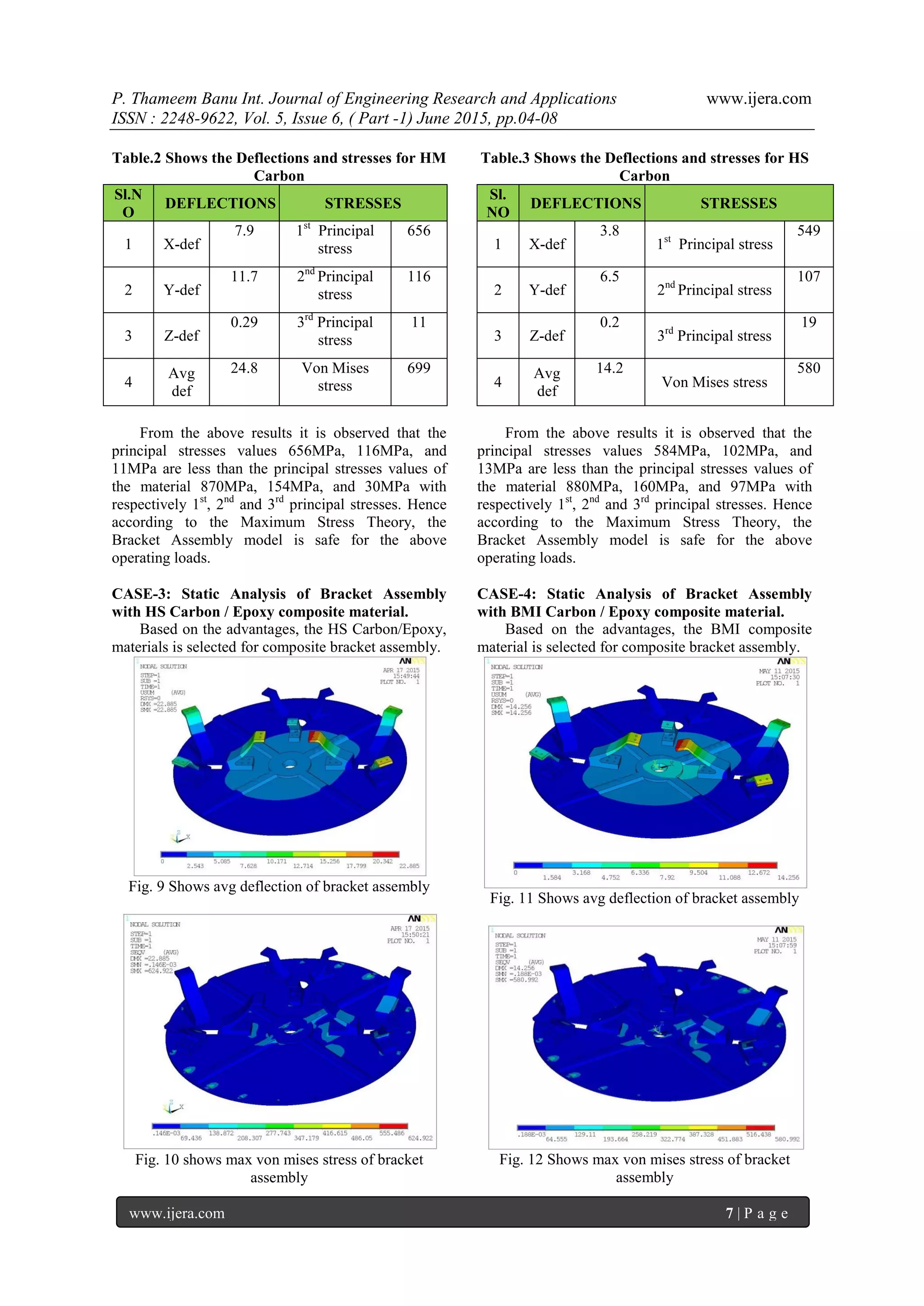
From the above results it is observed that the
principal stresses values 549MPa, 107MPa, and
19MPa are less than the principal stresses values of
the material 765MPa, 168MPa, and 32MPa with
respectively 1st
, 2nd
and 3rd
principal stresses. Hence
according to the Maximum Stress Theory, the
Bracket Assembly model is safe for the above
operating loads.
VII. CONCLUSIONS
In the present project a Bracket Assembly has
been modeled for static loading conditions with
different material properties.
From the above analysis it is concluded that the
Bracket Assembly has stresses and deflections
within the design limits of the aluminum alloy
material and composite materials (HM Carbon
/epoxy, HS Carbon /epoxy and BMI Carbon
/epoxy,).
From the above analysis it is also concluded that
the HS Carbon /epoxy composite Bracket
Assembly model having high factor of safety
(1.4) than the other materials and also have less
weight than the aluminum alloy model, because
of the HS Carbon /epoxy density is less than the
aluminum alloy.
REFERNECES:
[1] Materials Science And Engineering – Vol.
III – Aerospace and Space Materials – M.
Peters and C. Leyens
[2] Dieter G. E. (1997). ASM Handbook
Materials Selection and Design, Vol. 20,
pp.900.Materials Park, OH: ASM
International. [Comprehensive overview on
design concepts and criteria, design tools,
materials properties and selection, and
manufacturing aspects of design.]
[3] Vasudevan A. K. and Doherty, R. D.
(1989).Aluminium Alloys– Contemporary
Research and Applications, pp.702. San
Diego, CA: Academic Press. [Research and
technology on processing, structure and
properties of present and future Al alloys.]
[4] E.L. Wilson, “Automation of the Finite
Element Method—A personal Historical
View,” Finite Element in Analysis and
Design, vol.13, Nos. 2&3, 1993, pp- 91-104
[5] HarrisS,B. A perspective view of composite
materials. Mat & Design, vol 12, no. 5.1991.
pp. 259-271.
[6] Carter ,F.C., and Paul,D.E. Material science
and engineering. Ohio, ASM
International,1991 351 pp
[7] Bodily B, Heinimann M, Bray G, Colvin E,
Witters J. Advanced aluminum and
aluminum lithium solutions for derivative
and next generation aerospace structures.
SAE paper no 2012-01-1874](https://image.slidesharecdn.com/b56010408-150801062757-lva1-app6892/75/Modeling-and-Analysis-of-Bracket-Assembly-in-Aerospace-Industry-5-2048.jpg)

The document presents a study on the modeling and static analysis of a bracket assembly used in the aerospace industry, specifically for carrying fuel and air tanks. The analysis involves the use of NX-CAD for modeling and ANSYS for finite element analysis to determine the stresses and deflections under pressure loads. The findings conclude that the assembly is safe under various loading conditions and that composite materials, particularly hs carbon/epoxy, offer advantages in terms of safety and weight compared to aluminum alloy.