1. 1
Experimental Co-relation of Induction Welded Bead’s Burst Pressure using
Finite Element Techniques
Praveen S R, Dr. Roberto Cammino
Independent Research Project, MMAE 594
Illinois Institute of Technology, Illinois 60616
Abstract – This report describes the results of a
project focused on obtaining the yield stress at the
weld bead of a vibration welded pressure vessel. The
burst pressure of 0.508 bar was obtained from the
hydrostatic pressure test data performed
experimentally. The aim of this project is to verify the
amount of stress generated at the weld bead as it is
observed in the hydrostatic pressure test that the
rupture occurs in this region and formulate a failure
criterion. Additionally, the project investigates the
best methodology of mesh by playing with the various
parameters like geometric modelling, order of
elements and type of contact in Hyper mesh 13.0 in
order to obtain maximum correlation with
experimental data. The material used for the vessel is
Thermylene (a polypropylene composite material
which is proprietary to Asahi Kasei Plastics NA) and
a bonding resin compound for the bead. The analysis
consists of Non-Linear Geometric Static simulation of
applying 0.075 MPa of pressure (to get more data
points in yield condition and observe geometric
behavior) to the vessel using Finite Element Analysis.
Both the full and quarter model was Meshed using
Hypermesh and analyzed in ABAQUS. The results
obtained from the analysis were displayed using
stress plots.
I. INTRODUCTION
Typical joining methods for plastic parts are
screwing, snap- and press-fitting, gluing and welding.
Welding is an effective method for permanently joining
plastic components. There are various welding
techniques such as spin, ultrasonic, friction (Vibration),
laser and hot plate welding. The friction or vibration
welding process is ideally suited for welding of
compatible thermoplastic parts along flat seams which
have to be high strength, pressure tight and hermetically
sealed. The most effective analogy to demonstrate this
process is pressing and rubbing your hands together to
generate frictional heat. The same principle is applied for
joining thermoplastic parts. It is the ability to control the
frictional process that makes vibration welding such a
very precise and repeatable process in serial production.
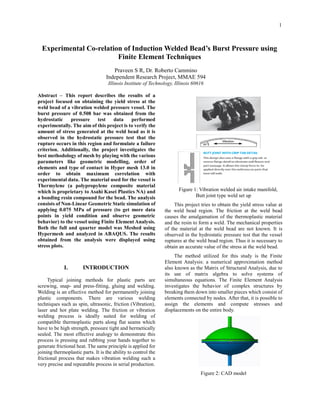
Figure 1: Vibration welded air intake manifold,
Butt joint type weld set up
This project tries to obtain the yield stress value at
the weld bead region. The friction at the weld bead
causes the amalgamation of the thermoplastic material
and the resin to form a weld. The mechanical properties
of the material at the weld bead are not known. It is
observed in the hydrostatic pressure test that the vessel
ruptures at the weld bead region. Thus it is necessary to
obtain an accurate value of the stress at the weld bead.
The method utilized for this study is the Finite
Element Analysis: a numerical approximation method
also known as the Matrix of Structural Analysis, due to
its use of matrix algebra to solve systems of
simultaneous equations. The Finite Element Analysis
investigates the behavior of complex structures by
breaking them down into smaller pieces which consist of
elements connected by nodes. After that, it is possible to
assign the elements and compute stresses and
displacements on the entire body.
Figure 2: CAD model
2. 2
II. METHODS
SI (mm) system of units were followed everywhere to
keep it consistent. The process of simulation follows
three main steps:
Preprocessing
At first a full CAD model of the vessel was created in
Creo Parametric 2.0. This geometry was then meshed in
Hypermesh. The ABAQUS student version restricted the
mesh size to 100,000 nodes hence there was restriction
to move on to second order elements. A membrane was
created by dragging the elements of the lower weld bead
and the node was TIED to the other weld bead. Results
were only obtained for a refined first order element size
of 2. Also, it was concluded form Abaqus postprocessor
that on analyzing the stress distribution that S11 & S22
have no impact on the stress distribution along the weld
beads. All nodes at the 2 supports were fixed and
elements in the internal membrane were applied with
pressure of 0.075 Mpa. General study between fixed and
float type of tetramesh was the major take away and it
was observed that the fixed mesh was preferable for a
mapped mesh.
Figure 3: Mesh of Full model with bead
As a result, a quarter geometry was then meshed in
Hypermesh. A numerous possibilities of options arose
with the freedom of the quarter model. Consistent results
were obtained in the quarter model as that of full model.
TIE command and Node-Node matching type of contact
were easier to apply for the quarter model.
Figure 4: Mesh of Quarter model with bead
Iterations of Analysis performed on the quarter model
in order to deduce best Mesh technique:
Float tetramesh with 1st
order element size 1 with
TIE command.
Fixed tetramesh with 1st
order element size 2 with
TIE command.
Fixed tetramesh with 2nd
order element size 2 with
TIE command.
Dragged elements for the membranes and fixed
tetramesh with 1st
order element size 2 with TIE
command.
Dragged elements for the membranes and fixed
tetramesh with 2nd order element size 2 with TIE
command.
Dragged elements for the membranes and float
tetramesh with 2nd
order element size 2 with TIE
command.
Dragged elements for the membranes and fixed
tetramesh with 1st
order element size 2 with TIE
command with 2 elements across the hemispherical
wall.
Dragged elements for the membranes and fixed
tetramesh with 1st
order element size 2 with Node-
Node matching across the contour.
2 layers of dragged elements for the membranes and
fixed tetramesh with 1st
order element size 2 with
TIE command.
2 layers of dragged elements for the membranes and
fixed tetramesh with 2nd order element size 2 with
TIE command.
2 layers of dragged elements for the membranes and
fixed tetramesh with 1st
order element size 2 with
Node-Node Matching
Processing
In this step, the elements were assigned to their
material properties. Asahi Kasei Plastics had provided
the test data for thermylene and the material properties
were found using the 0.2% offset method. For the Resin,
Asahi Kasei plastics had sent an image of the material
stress strain plot in a UTM machine. Datathief was used
Dragged
elements
Membrane
representing
bonding resin
3. 3
to interpolate the young’s modulus and yield stress of the
same.
Table 1: Material Properties
Figure 5: Boundary conditions and loads
Graph 1: Poly-Propelene Stress v/s Strain plot
Graph 2: Bonding Resin Stress v/s Strain plot
Post Processing
The next step was to export the input file and solve
it in ABAQUS. The results obtained from the analysis
were analyzed. The Von misses stress and the axial stress
component that is S33 for the full and quarter model for
all the iterations. Von-Misses is also considered although
S33 was observed to be the failure criteria since it’s a
conservative average energy which could be universally
correlated with any weld bead orientation.
III. RESULTS
Table 2: Results
-20
0
20
40
60
80
-0.01 0 0.01 0.02 0.03 0.04
TRUE STRESS VS TRUE STRAIN
True Stress
(Mpa)
offset
-10
0
10
20
30
40
50
0 0.05 0.1 0.15
TRUE STRESS Vs TRUE STRAIN
True Stress
(Mpa)
Offset
0.75bar Elsize Order Smises S11 S22 S33
fixedtetramesh 2.5 1 4.5 1.5 3.5 5.5
floattetramesh 2 1 4 1 2.5 5.5
draggedelementsfloat
4,2(refinementat
weldbead)
1 3.5 2 5 9
floattetramesh 1 1 6 9
fixedtetramesh 2 1 5 6.5
fixedtetramesh 2 2 6 7.5
draggedelementsfixedtetramesh 2 1 5 7
draggedelementsfixedtetramesh 2 2 6.5 8.5
draggedelementsfloattetramesh 2 2 6.5 8.5
draggedelementsfixed-mappedtetramesh 2 1 4.7 6
draggedelementsfixed-mappedtetramesh 2 2 6 7.5
draggedelementsfixed-mappedmesh(2elementsacrossthewallof
bothhemisphere)
2 1 5 6.5
draggedelementsfixed-mappedtetramesh(2membranesdragged) 2 1 4.5 6
draggedelementsfixed-mappedtetramesh(2membranesdragged) 2 2 5 7.5
draggedelementsmappedmeshfixed
(NodemappingwithoutTIEcommand-2membranesdragged)
2 1 4 6
draggedelementsmappedmeshfixed
(NodemappingwithoutTIEcommand)
2 2 4 6
FullModel
ConclusionthatS11&S22don’thaveanyimpactonweldbeadfailurecriteriasincefailuredoesn’toccurontheweldbead
Quarter
Fixed Nodes
(All Dof)
4. 4
The analysis was performed and the Von Mises and
S33 axial stress component data was recorded by probing
the elements in the weld bead region. The mesh model in
each type of analysis was solved using linear (1st
order)
and Quadratic (2nd
order) elements. The axial stress
component has been recorded, because at the weld bead
region the elements primarily undergo tension.
The element size (h) is constant in all the analysis
since ABAQUS student edition limits node count to
100,000. Thus the finest possible mesh was created and
an order (p) change was applied. Naturally, the second
order elements which are less rigid represent better
physics and produce more accurate results.
The following images are the stress plots for the best
meshed model of the quarter model (2 membranes
dragged, fixed tetramesh, 2 element size, 2nd
order)
Figure 6: Mises Stress Plot overall model (2
dragged elements)
Figure 7: Mises Stress plot along weld bead – 5
Mpa (Probed average value)
Figure 8 : S33 Stress– 7.5 Mpa (Probed averaged
value)
Failure only across weld bead (similar to experimental
behavior)
5. 5
Figure 9 : Fig 8 zoomed at weld bead
Fig 10 : S11 Stress– 4 Mpa (Probed average value)
Fig 11 : S22 Stress– 2.5 Mpa (Probed average value)
Fig 12 : U mag value
6. 6
Graph 3: S33 behavior at each load step
Similar results and plots were obtained for all the
iterations of the quarter model.
The above graph depicts the linear behaviour of the
elastic plastic model.
IV. DISCUSSION & ANALYSIS OF
RESULTS
In the full model analysis, a basis was obtained in
the expected stress distributions on application of burst
pressure. However, was unable to move to second order
due to solver constraint.
The full model with refinement at the weld bead of
element size 2 were satisfying criteria failure at the weld
bead region but the mesh wasn’t mapped.
In the quarter model, element size 1 was consistent
with the full model dragged elements. Also, dragged
elements had provided the flexibility of applying base
resin properties directly at the interface of the weld beads
which promote better replication of actual physics in the
problem.
Increasing the elements across the wall of the cereal
bowl has no effect on the stress distribution.
Second order dragged elements across both sides of
the weld bead which are mapped meshed is the best
meshing technique observed.
Node matching of first order elements produce
consistent results as that of first order dragged elements
of mapped mesh. Thus, TIE command is an equivalent
substitute instead of mapping each node across the
interface of the 2 weld beads.
Failure criteria of the Abaqus simulation is 7.5 MPa
for the given weld bead geometry and material model at
0.75 bar burst pressure and 5.5 Mpa for 0.508 bar burst
pressure. Further investigation and experimental
validation is required to get the exact mechanical
property of the material at the weld bead.
.
V. CONCLUSION
Using the software Hypermesh and Abaqus, it was
shown that the yield stress value for the material at the
weld bead region was approximately 7.5 Mpa. This value
is less compared to the yield stress value of Poly-
propelene and the resin. Thus it can stated that further
analysis needs to be done to study the material properties
of the weld bead region and to develop a new material
model based on tensile testing of Collar Chip Weld bead
in Universal Testing Machine.
VI. REFERENCES
1. Algor: Element information. Retrieved from
http://www.algor.com/news_pub/tech_white_p
apers/four_node/default.asp
2. Emerson industrial: Vibration welding data.
Retrieved from
http://www.emersonindustrial.com/en-
US/documentcenter/BransonUltrasonics/Plasti
c%20Joining/Non-
Ultrasonics/VW_Tech_Info.pdf
3. Material datasheets at Asahi Kasei Plastics NA
Inc.
4. Abaqus manual :
http://129.97.46.200:2080/v6.13/