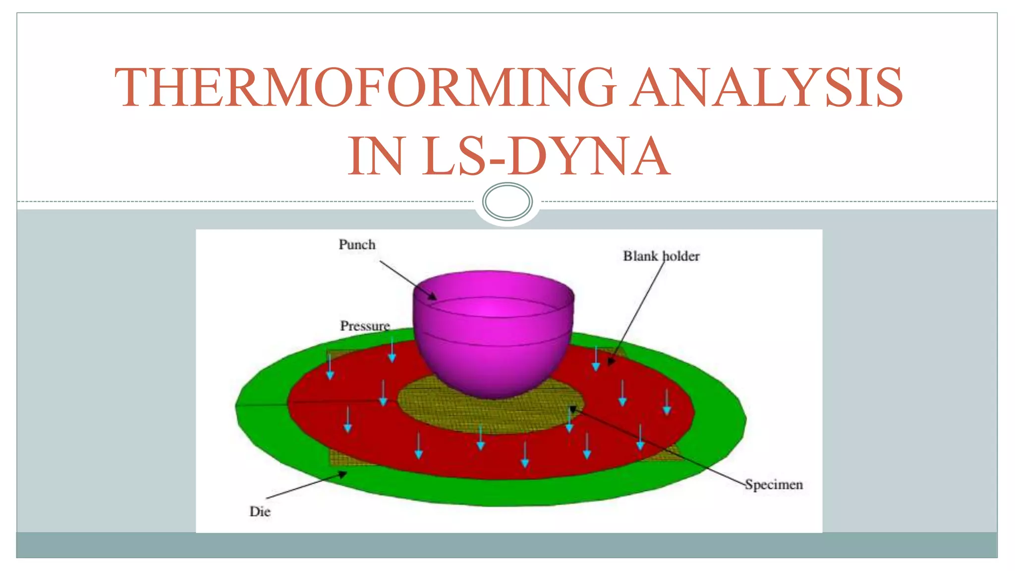
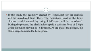
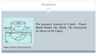
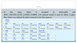
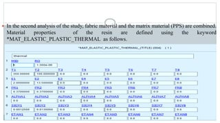
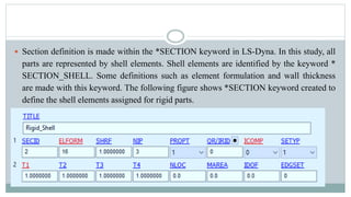
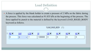
This document discusses using LS-DYNA software to simulate the thermoforming process. It introduces the geometry and finite element model created in HyperMesh and LS-Prepost. Shell elements are used to model the thin structures. Material models are defined for the rigid tools and deformable fabric. The forming process is defined through contact definitions, prescribed motion of the punch, and blank holder force. Results of the fiber orientation and shear angle distribution are compared to previous work. Parameters like yarn thickness and friction could not be exactly determined and may contribute to differences in results.
![Unit System
LS-Dyna does not allow to define any unit. So the values used in the
analysis should be entered according to a suitable unit system. In this
study Table 1 (c) compatible unit system was used [4].](https://image.slidesharecdn.com/compositeforminginlsdyna-230228133742-5eb30df6/85/Composite-Forming-in-Ls-Dyna-pptx-6-320.jpg)
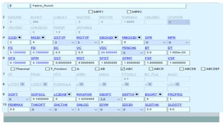
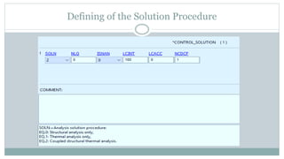
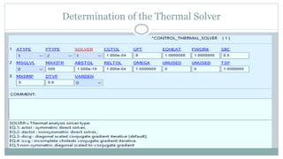
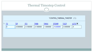
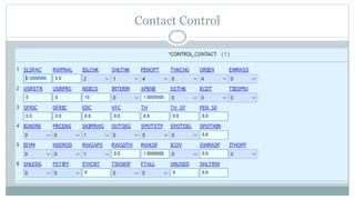
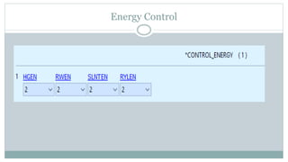
![Keywords Defined for LS-DYNAAnalysis
The creation of the finite element model in Ls-Dyna is done by a set of
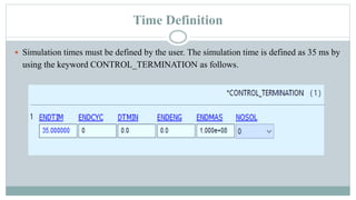
keywords. These definitions includes simulation time, simulation
speed, contact state and friction force, material model and type,
moment of inertia, wall thicknesses, degrees of freedom, loading
conditions and various simulation control parameters. These keywords
can be entered in the system manually or by using the LS-Prepost
interface [5].](https://image.slidesharecdn.com/compositeforminginlsdyna-230228133742-5eb30df6/85/Composite-Forming-in-Ls-Dyna-pptx-7-320.jpg)

![Results
The simulation is applied for two initial fiber orientations of E-glass fiber fabric, 0˚/90˚
and -45˚/+45˚. The final shape of the draped fabric is compared with the Tabiei’s result.
Comparison of draped shapes for 0˚/90˚ orientation a) Tabiei’s result [3] b) Simulation result](https://image.slidesharecdn.com/compositeforminginlsdyna-230228133742-5eb30df6/85/Composite-Forming-in-Ls-Dyna-pptx-31-320.jpg)
![Comparison of draped shapes for -45˚/+45˚ orientation a) Tabiei’s result [3] b) Simulation result](https://image.slidesharecdn.com/compositeforminginlsdyna-230228133742-5eb30df6/85/Composite-Forming-in-Ls-Dyna-pptx-32-320.jpg)
![ Distortion angles were determined along the diagonal axis starting from the center point
for 0˚/90˚ orientation, along the horizontal axis starting from the center point for -
45˚/+45˚ orientation.
Comparison of the angular distortions for 0˚/90˚ orientation a) Tabiei’s result [3] b) Simulation result](https://image.slidesharecdn.com/compositeforminginlsdyna-230228133742-5eb30df6/85/Composite-Forming-in-Ls-Dyna-pptx-33-320.jpg)
![Comparison of the angular distortions for -45˚/+45˚ orientation a) Tabiei’s result [3] b) Simulation result](https://image.slidesharecdn.com/compositeforminginlsdyna-230228133742-5eb30df6/85/Composite-Forming-in-Ls-Dyna-pptx-34-320.jpg)
![REFERENCES
[1] Ivanov I., Method development for finite element impact simulations of composite materials, University of
Cincinnati, 2002.
[2] Ivanov I., Tabiei A., Loosely woven fabric model with viscoelastic crimped fibres for ballistic impact simulations,
International Journal for Numerical Methods in Engineering, 61, 1565-1583, 2004.
[3] Tabiei A., Murugesan R., Thermal structural forming simulation of carbon and glass fiber reinforced plastics
composites, International Journal of Composite Materials, 5(6), 182-194, 2015.
[4] Sözen L., Boru bükme operasyonu sonucunda meydana gelen geri yaylanma miktarının öngörülmesi, TOBB ETÜ,
2011.
[5] Livermore Software Technology Corporations (LSTC), LS-DYNA Keyword User’s Manual - Volume I, 2018.
[6] Livermore Software Technology Corporations (LSTC), LS-DYNA Keyword User’s Manual - Volume II, 2018.](https://image.slidesharecdn.com/compositeforminginlsdyna-230228133742-5eb30df6/85/Composite-Forming-in-Ls-Dyna-pptx-40-320.jpg)