This document provides information on designing a connecting rod, including:
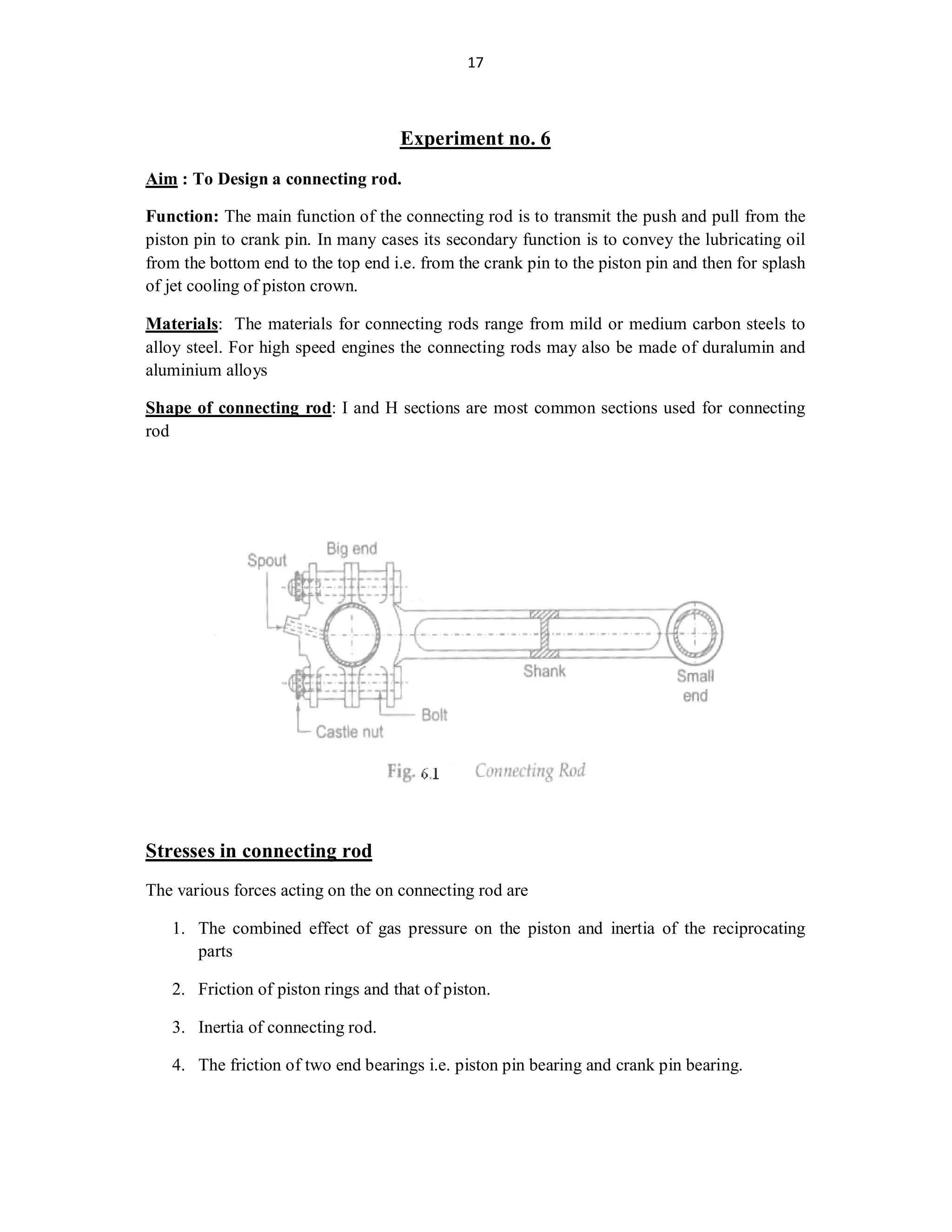
1. The connecting rod transmits force from the piston to the crankpin. Stresses on it include gas pressure, inertia, friction, and its own inertia.
2. Formulas are given to calculate the load due to gas pressure and piston inertia, friction forces, and the connecting rod's inertia forces.
3. Maximum bending moment and stress on the connecting rod are calculated. A buckling load formula is also provided. The connecting rod design must withstand the buckling load with an appropriate factor of safety.
The document discusses key concepts related to chain drives, including:
1) It defines common terms used in chain drives like pitch, pitch circle diameter, and velocity ratio.
2) It describes different types of chains including hoisting/hauling chains, conveyor chains, and power transmitting chains like roller chains and silent chains.
3) It provides equations for calculating important chain drive dimensions and specifications like length of chain, center distance, factor of safety, power transmitted, and number of teeth on sprockets.
ME6601 - DESIGN OF TRANSMISSION SYSTEM NOTES AND QUESTION BANK ASHOK KUMAR RAJENDRAN
This document contains the question bank for the subject ME6601 - Design of Transmission Systems for the sixth semester Mechanical Engineering students of RMK College of Engineering and Technology. It is prepared by R. Ashok Kumar and S. Arunkumar, faculty of the Mechanical Engineering department.
The question bank contains 190 questions divided into two parts: Part A containing conceptual questions and Part B containing design/numerical problems. The questions cover the five units of the subject - Design of Flexible Elements, Spur Gears and Parallel Axis Helical Gears, Bevel, Worm and Cross Helical Gears, Gear Boxes, and Cams, Clutches and Brakes. Most questions are related
This document provides an overview of dynamics of machines including:
1. It defines force, applied force, constraint forces, and types of constrained motions like completely, incompletely, and successfully constrained motions.
2. It discusses static force analysis, dynamic force analysis, and conditions for static and dynamic equilibrium.
3. It covers concepts like inertia, inertia force, inertia torque, D'Alembert's principle, and principle of superposition.
4. It derives expressions for forces acting on the reciprocating parts of an engine while neglecting the weight of the connecting rod.
Unit 2 Design Of Shafts Keys and CouplingsMahesh Shinde
This document provides information about the design of shafts, keys, and couplings. It discusses transmission shafts, stresses induced in shafts, and shaft design based on strength and rigidity. It presents formulas for shaft design using maximum shear stress theory, distortion energy theory, and the ASME code. Several examples are provided to demonstrate how to calculate the diameter of a shaft given the power transmitted, loads on the shaft, material properties, and other parameters using these theories and codes. Assignments involving similar calculations of shaft diameters are presented.
Basic types of screw fasteners, Bolts of uniform
strength, I.S.O. Metric screw threads, Bolts under
tension, eccentrically loaded bolted joint in shear,
Eccentric load perpendicular and parallel to axis of
bolt, Eccentric load on circular base, design of Turn
Buckle.
Surface roughness metrology deals with basic terminology of surface,surface roughness indication methods,analysis of surface traces, measurement methods,surface roughness measuring instruments such as Stylus Probe Instrument, Profilometer, Tomlinson Surface Meter ,The Taylor-Hobson Talysurf etc.This is very useful for diploma,degree engineering students of mechanical,production,automobile branch
This document outlines an assignment for students to evaluate the performance of a 4-stroke petrol engine. It discusses key performance parameters like power, efficiency, fuel consumption, emissions. The objective is for students to understand how to calculate speed, fuel use, air use, and evaluate exhaust smoke and emissions in order to optimize engine performance. Parameters like power, efficiency, emissions are defined and methods to test them such as using a dynamometer are described.
This document provides notes on dynamics of machines from a professor at Kalaignarkarunanidhi Institute of Technology in Coimbatore, India. It covers topics like vibratory motion, types of vibrations including free, forced and damped vibrations. It defines key terms used in vibratory motion like period, cycle, frequency. It describes different types of free vibrations such as longitudinal, transverse and torsional vibrations. Methods to determine the natural frequency of free longitudinal vibration including equilibrium method, energy method and Rayleigh's method are presented. The document also discusses the effect of inertia of constraints in longitudinal vibration and frequency of free damped vibrations. An example problem is given to determine frequency of longitudinal
The document discusses stress concentration and fatigue failure in machine elements. It defines stress concentration as the localization of high stresses due to irregularities or abrupt changes in cross-section. Stress concentration can be reduced by avoiding sharp changes in cross-section and providing fillets and chamfers. Fatigue failure occurs when fluctuating stresses cause cracks over numerous load cycles. The endurance limit is the maximum stress amplitude that causes failure after an infinite number of cycles. Factors like stress concentration, surface finish, size, and mean stress affect the endurance limit. Designs should minimize stress raisers and protect against corrosion to prevent fatigue failures.
Whirling of shafts occurs due to rotational imbalance of a shaft, even in the absence of external loads, which causes resonance to occur at certain speeds, known as critical speeds.
The document discusses the fundamentals of theory of machines and its subdivisions. It covers the following key points:
1. Theory of machines deals with the study of relative motion between machine parts and forces acting on them. It is subdivided into kinematics, dynamics, kinetics, and statics.
2. Kinematics studies relative motion, dynamics studies forces and their effects on moving parts, kinetics studies inertia forces, and statics studies forces on stationary parts.
3. Fundamental concepts like space, time, matter, body, mass, and force are defined. Newton's laws of motion are also summarized.
4. Methods for analyzing reciprocating engines like graphical and analytical methods are outlined. Forces
1. A shaft transmits power and rotational motion and has machine elements like gears and pulleys mounted on it.
2. Press fits, keys, dowel pins, and splines are used to attach machine elements to the shaft.
3. The shaft rotates on rolling contact or bush bearings and uses features like retaining rings to take up axial loads.
4. Couplings are used to transmit power between drive and driven shafts like between a motor and gearbox.
Shaft & keys (machine design & industrial drafting )Digvijaysinh Gohil
This document discusses different types of shafts, keys, and their design considerations. It contains the following key points:
1. Shafts can be classified based on their shape (solid or hollow), application (transmitting, machine, spindle), and construction (rigid or flexible).
2. Keys are used to connect rotating machine elements to shafts and prevent relative motion. Common types include rectangular, square, parallel, gib-head, feather, and woodruff keys.
3. Shaft design considers factors like bending moment, shear stress, and material properties. Hollow shafts have higher strength-to-weight ratio than solid shafts of the same size.
- The document discusses different types of springs including helical compression springs, helical extension springs, helical torsion springs, and multileaf springs.
- It describes the functions and applications of springs which include absorbing shocks and vibrations, storing energy, and measuring forces.
- Key terms related to helical spring design are defined such as wire diameter, mean coil diameter, spring index, solid length, compressed length, free length, and pitch. Stress and deflection equations for helical spring design are also presented.
PPT describes the engine performance parameters of the I.C. engine.
Engine performance is an indication of the degree of success of the engine performs its assigned task, i.e. the conversion of the chemical energy contained in the fuel into the useful mechanical work. The engine performance is indicated by the term efficiency, η. Five important engine efficiencies and other related engine performance parameters are:
Power
Indicated Thermal Efficiency (ηith)
Brake Thermal Efficiency (ηbth)
Mechanical Efficiency (ηm)
Volumetric Efficiency (ηv)
Relative Efficiency or Efficiency Ratio (ηrel)
Mean Effective Pressure (Pm)
Specific Fuel Consumption (sfc)
Fuel-Air or Air-Fuel Ratio (F/A or A/F)
Calorific Value (CV)
Power:-
The main purpose of running an engine is to obtain mechanical power.
Brake Power (B.P.)
The power developed by an Engine at the output shaft is called the brake power.
Brake Power= Brake Workdone/Time
B.P.=BWD/sec.
Indicated power (I.P.)
The total power developed by Combustion of fuel in the combustion chamber is called indicated power.
Indicated Power= Indicated Workdone/Time
I.P.=IWD/sec.
Frictional Power (F.P.)
The difference between I.P. and B.P. is called frictional power (f.p.).
FP = IP – BP
Thermal Efficiency (ηth)
Thermal efficiency is the ratio of Power to energy supplied by the fuel.
ηth= Power/ Energy
In I.C. Engine, thermal efficiency can be classified into two categories i.e.
Indicated Thermal Efficiency (ηith)
Indicated thermal efficiency is the ratio of indicated power to the heat supplied or added.
ηith= IP/Qs
2. Brake Thermal Efficiency (ηith)
Brake Thermal Efficiency is the ratio of brake power to the heat supplied or added.
ηbth= BP/Qs
Volumetric Efficiency (ηv)
This is one of the most important parameters which decide the performance of four-stroke engines. Four stoke engines have distinct suction stoke, volumetric efficiency indicates the breathing ability of the engine.
Volumetric efficiency is defined as the ratio of actual flow rate of air into the intake system to rate at which the volume is displaced by the system.
ηv= (푚 ̇"a/a" )/(푉푑푖푠푝푎푐푒푑 푋 푁/2)
"a"= Inlet density is taken atmospheric air density
N= Number of the cylinder in use
,
diploma mechanical engineering
,
mechanical engineering
,
machine design
,
design of machine elements
,
knuckle joint
,
failures of knuckle joint under different streses
,
fork end
,
single eye end
,
knuckle pin
This presentation contains basic idea regarding spur gear and provides the best equations for designing of spur gear. One can Easily understand all the parameters required to design a Spur Gear
This document discusses the design of journal bearings. It begins by introducing journal bearings and how they operate by allowing sliding along a circular surface to handle radial loads. It then describes the different types of journal bearings according to their angle of contact and lubricating layer thickness. The document outlines the materials commonly used for journal bearings and defines important terms in hydrodynamic journal bearings. It presents two main design methods - the M.D. Hersey method and the A.A. Raimondi and J. Boyd method - and provides overviews of the steps and considerations involved in each.
Coupling is one kind of mechanical device which is used to connect two shafts together at their
ends for the purpose of transmitting power.
The primary purpose of couplings is to join two pieces of rotating equipment while permitting
some degree of misalignment or end movement or both.
A rigid coupling is a unit of hardware used to join two shafts within a motor or mechanical system.
It may be used to connect two separate systems, such as a motor and a generator, or to repair a
connection within a single system. A rigid coupling may also be added between shafts to reduce
shock and wear at the point where the shafts meet.
Flanged coupling is a type of rigid coupling in which two co-linear shafts are connected by the
flanges. The coupling enables torque transmission between the shafts & prevents relative rotation
between them.
In the project work a flanged coupling was made by local material available & the analysis of
various stresses & safety factor was also performed.
The outcome of analysis is there’s no danger of failure by pure shear, even if a fatigue strength
reduction factor is included, but this same section may have severe & undefinable bending stresses
on it if the flanges are imperfectly aligned, and they surely will be. The bolts bending was neglected
since they were too small compared to the result outcome.
Finally, the computed factor of safety of the flanges suggest that it would withstand repeated
bending if the misalignment is small.
The document discusses the design of flywheels. Flywheels store kinetic energy and are used to reduce power fluctuations in engines and machines. They have a heavy rotating rim connected to a central hub by several arms. Flywheels can be made of cast iron due to its ability to absorb vibrations. The stresses in flywheels include tensile stresses from centrifugal force and bending stresses from the arms resisting torque fluctuations. Proper design of the rim, arms, and materials is needed to ensure flywheels withstand the stresses during high-speed rotation.
The document discusses the design of a flywheel. A flywheel is an inertial energy storage device that absorbs mechanical energy during periods of high energy supply and releases it during periods of high energy demand. Flywheels smooth out torque fluctuations in machines like engines. Traditional flywheels are made of cast iron due to its ability to damp vibrations, but modern flywheels use composite materials. The design of a flywheel involves determining the required energy storage and moment of inertia, and defining a geometry that meets these requirements safely. Flywheels find applications in engines, compressors, and the electricity grid where they provide backup power.
This document contains a thermodynamics lab report submitted by a mechanical engineering student. The report summarizes 11 experiments conducted in the thermodynamics lab, including demonstrations of internal combustion engine components and systems, different engine types, and measurements. It also includes detailed descriptions of 3 specific experiments on introducing the lab and layout, demonstrating main engine components, and demonstrating 2-stroke and 4-stroke engines.
The document contains 38 questions related to machine design. The questions cover topics such as standardization of sizes, tolerances, fits, design of joints, shafts, levers, frames and other machine elements. Design calculations are required to determine dimensions that satisfy given loading and stress criteria. Materials, their properties and appropriate factors of safety are provided. References for solutions and examples are given from standard machine design textbooks.
1. The document discusses the dynamics of machines and introduces the key concepts of kinematics, dynamics, kinetics, and statics as the four main branches of the theory of machines.
2. It then discusses static and dynamic force analysis and introduces concepts like inertia forces and torques. D'Alembert's principle is explained which states that inertia and external forces together result in static equilibrium.
3. Methods for dynamic analysis of reciprocating engines like graphical and analytical methods are introduced. Key forces on reciprocating parts like piston effort, connecting rod force, thrust, crank pin effort, and crank effort are defined.
1. The document discusses different types of hydrostatic transmissions, including open-circuit, closed-circuit, and reversible systems.
2. Key components of hydrostatic transmissions are described, including the charge pump, relief valves, motors, and pumps. The selection process for pumps and motors is also outlined.
3. Various pressure control valves used in hydrostatic systems are explained, such as relief valves, counterbalance valves, sequence valves, and pressure reducing valves. Shuttle valves are also introduced.
The document discusses different types of brakes used in vehicles and machinery. It defines key terms related to brakes such as tangential braking force, normal force, coefficient of friction, heat generated during braking. It then describes different types of brakes in detail including single block/shoe brake, pivoted block/shoe brake, band brake, band and block brake, internal expanding brake. Equations are provided for calculating forces, torque, energy absorbed during braking. Materials used for brake linings and their properties are also summarized.
ME010 801 Design of Transmission Elements
(Common with AU010 801)
Teaching scheme Credits: 4
2 hours lecture, 2 hour tutorial and 1 hour drawing per week
Objectives
To provide basic design skill with regard to various transmission elements like clutches, brakes, bearings and
gears.
Module I (20 Hrs)
Clutches - friction clutches- design considerations-multiple disc clutches-cone clutch- centrifugal clutch -
Brakes- Block brake- band brake- band and block brake-internal expanding shoe brake.
Module II (17 Hrs)
Design of bearings - Types - Selection of a bearing type - bearing life - Rolling contact bearings - static
and dynamic load capacity - axial and radial loads - selection of bearings - dynamic equivalent load -
lubrication and lubricants - viscosity - Journal bearings - hydrodynamic theory - design considerations -
heat balance - bearing characteristic number - hydrostatic bearings.
Module III (19 Hrs)
Gears- classification- Gear nomenclature - Tooth profiles - Materials of gears - design of spur, helical,
bevel gears and worm & worm wheel - Law of gearing - virtual or formative number of teeth- gear tooth
failures- Beam strength - Lewis equation- Buckingham’s equation for dynamic load- wear loadendurance strength of tooth- surface durability- heat dissipation - lubrication of gears - Merits and
demerits of each type of gears.
Module IV (16 Hrs)
Design of Internal Combustion Engine parts- Piston, Cylinder, Connecting rod, Flywheel
Design recommendations for Forgings- castings and welded products- rolled sections- turned parts,
screw machined products- Parts produced on milling machines. Design for manufacturing - preparation
of working drawings - working drawings for manufacture of parts with complete specifications including
manufacturing details.
Note: Any one of the following data book is permitted for reference in the final University examination:
1. Machine Design Data hand book by K. Lingaiah, Suma Publishers, Bangalore/ Tata Mc Graw Hill
2. PSG Design Data, DPV Printers, Coimbatore.
Text Books
1. C.S,Sarma, Kamlesh Purohit, Design of Machine Elements Prentice Hall of India Ltd NewDelhi
2. V.B.Bhandari, Design of Machine Elements McGraw Hill Book Company
3. M. F. Spotts, T. E. Shoup, Design of Machine Elements, Pearson Education.
Reference Books
1. J. E. Shigley, Mechanical Engineering Design, McGraw Hill Book Company.
2. Juvinall R.C & Marshek K.M., Fundamentals of Machine Component Design, John Wiley
3. Doughtie V.L., & Vallance A.V., Design of Machine Elements, McGraw Hill Book Company.
4. Siegel, Maleev & Hartman, Mechanical Design of Machines, International Book Company
Lecture note on Shaft design of machine element.pptxfetena
Solid shaft
The diameter of a solid steel shaft transmitting 25 HP at 200 rpm can be determined from:
16T
πτall
d = √
Where T is the transmitted torque calculated from power and rpm, and τall is the allowable shear stress.
Hollow shaft
If a hollow shaft replaces the solid shaft, assuming an inner to outer diameter ratio of 0.5, the inner and outer diameters can be determined from:
16T
πτall(1 − k4)
do = √
Where k is the ratio of inner to outer diameter.
This document provides an overview of flywheels and their use in smoothing out torque fluctuations in machines like engines and presses. It defines key terms like the coefficient of fluctuation of speed and energy. It shows how to calculate the required moment of inertia of a flywheel to keep a machine's speed within specified limits given the torque-angle diagram. It also derives the effective moment of inertia for geared systems. Several example problems are worked through to demonstrate these calculations.
This document discusses various types of brakes and dynamometers used in mechanical engineering. It describes shoe brakes, internally expanding shoe brakes, and how braking works when applied to rear wheels only, front wheels only, or all wheels of a vehicle. It also covers different types of dynamometers used to measure power including pony brake, rope brake, epicyclic train, belt transmission, and torsion dynamometers. Example problems are provided to calculate braking torque and distance required to stop a vehicle under different braking conditions.
This document summarizes a student's seminar presentation on brakes. It discusses various types of brakes including band, shoe, and disc brakes. It describes the components and operation of simple and differential band brakes. It also provides an example problem calculating the braking torque of a differential band brake.
Brakes use friction between brake pads or shoes and the drum or disc to convert kinetic energy of a moving vehicle into heat energy, slowing the vehicle down. There are different types of brakes such as air brakes and hydraulic brakes. Dynamometers are used to measure the power output of engines. There are absorption dynamometers which absorb all the engine's energy as heat and transmission dynamometers which transmit the energy for work. Common absorption dynamometers are prony brake and rope brake dynamometers, while common transmission dynamometers are epicyclic train, belt transmission, and torsion dynamometers.
Design of Machine Elements - Unit 4 Proceduress Kumaravel
This document discusses the design of various machine elements including springs, leaf springs, belleville springs, flywheels, connecting rods, and bolts. It provides classifications and terms used in spring design. The design procedures outlined include selecting materials, determining specifications and dimensions, checking for stresses and deflections, and considering load arrangements. Factors like permissible stresses, safety factors, and empirical constants are incorporated based on the application and type of element.
This document describes the design and standardization of a toggle jack. It begins with an abstract that outlines the purpose and components of a toggle jack. It then provides background on toggle jacks and their advantages over other jack designs. The main body of the document details the design process, including formulas and sample calculations for sizing the screw, nut, pins, and links based on design loads. It presents a sample design calculation for a 3kN load using medium carbon steel for the screw and phosphor bronze for the nut. Charts of results show stress values remain below allowable limits. The conclusion indicates alloy steel and phosphor bronze is a suitable material combination that keeps stresses within safe limits compared to other materials.
A document discusses various types of brakes, including block or shoe brakes, band brakes, and internal expanding brakes. It provides examples to calculate braking torque, normal force, tension in brake bands, and forces required to stop motion. It explains factors like coefficient of friction, drum diameter, angle of contact, and fulcrum position impact brake design and performance. Design considerations include making brakes self-energizing without becoming self-locking. Materials and dimensions are selected based on stresses, pressures, and ability to dissipate heat from absorbed energy.
Design, fabrication and performance evaluation of melon shelling machineeSAT Journals
The document describes the design, fabrication, and testing of a melon shelling machine. It discusses the methodology used, including design calculations for components like the shelling cylinder, shaft, belt drive, and bearings. Testing showed the machine achieved 62.5-70.95% shelling efficiency depending on whether a flat bar or flexible rubber was used for shelling. While the flexible rubber achieved higher shelling, it also resulted in more partially shelled seeds. Overall, the machine was successful in improving melon shelling performance compared to traditional methods.
This document provides an overview of helical spring design and analysis. It discusses stresses in helical springs, deflection calculations, compression spring types, stability, materials selection, static design considerations, critical frequencies, and examples. The chapters cover key topics like curvature effects, stresses from torsion and shear, deflection-force relationships, buckling analysis, material properties, recommended design ranges, and the wave equation for vibrational frequency.
1) Springs are elastic elements that deflect under load and return to their original shape when unloaded. They come in various shapes and are classified by type, with helical springs being most common.
2) Helical springs are used to absorb shocks, store energy, measure forces, and control motion. The main types are compression and extension springs.
3) Springs are designed based on factors like the wire diameter, mean coil diameter, and spring index, which determines stresses and deflection. Proper design ensures springs function reliably under various loads.
1. A spring is an elastic element that deflects under load and returns to its original shape when the load is removed. Springs are commonly used to absorb shocks, measure forces, store energy, and apply or control motion.
2. The main types of springs are helical coil springs, torsion bar springs, leaf springs, volute springs, pneumatic springs, and Belleville springs. Helical coil springs can be compression or extension springs and can have standard, variable pitch, or conical coil designs.
3. The stress, deflection, and rate of springs is calculated based on factors like wire diameter, mean coil diameter, shear modulus, and spring index. Higher spring indices provide
The document discusses formulas for calculating various forces acting on components of internal combustion engines, including:
1. Piston effort (FP), which is affected by gas forces (FL), inertia forces (FI), and friction forces (RF).
2. Force along the connecting rod (FQ), thrust on the cylinder walls (FN), thrust on the crankshaft bearings, and crank-pin effort (FT).
3. Torque (T) on the crankshaft, which is calculated as the product of the crank-pin effort (FT) and the crank radius (r).
The document also provides example calculations using the formulas to determine pressure on slide bars,
This document discusses various types of brakes and dynamometers. It provides definitions of a brake, dynamometer, self-energizing brake, and self-locking brake. It describes absorption and transmission dynamometers. Prony brake, belt transmission, and torsion dynamometers are explained. Expressions are derived for braking torque in shoe brakes, band brakes, and drum brakes. Distinctions between simple and differential band brakes are outlined.
This document discusses the transmission components that transfer power from a 1.5kW motor operating at 2770rpm through multiple shafts and gears to feed rollers that plane wood. It describes the motor specifications and sizes of discs on the motor shaft and planing shaft. Ratios, speeds, and torque calculations are provided for two transmission configurations that allow the planing shaft to operate at either 7410rpm for planing or 2978rpm for drilling. Additional gearing and a chain drive the feed rollers to a constant speed of 63rpm, corresponding to a wood feed rate of 11.5cm/s.
The document discusses various types of frictional clutches, including disc clutches, cone clutches, and centrifugal clutches. It provides details on the structure and operating principles of single plate and multi-plate disc clutches. The torque transmission analysis for these clutches is presented based on both uniform pressure and uniform wear theories. Cone clutches are described as providing higher torque transfer compared to disc clutches of the same size. Centrifugal clutches are explained as using centrifugal force to automatically engage and disengage based on engine speed.
This document analyzes connecting rods used in internal combustion engines. It discusses the function of connecting rods, which is to transmit the thrust of the piston to the crankshaft, converting the reciprocating motion of the piston into rotational motion. It describes different types of connecting rods, including cast rods, forged rods, forged billet rods, and sintered rods. It also examines the forces acting on connecting rods, such as buckling load, and provides formulas for analyzing these forces. Dimensional analysis of connecting rod design is also presented. Connecting rods are crucial components that allow engines in vehicles and machinery to operate.
Introduction- e - waste – definition - sources of e-waste– hazardous substances in e-waste - effects of e-waste on environment and human health- need for e-waste management– e-waste handling rules - waste minimization techniques for managing e-waste – recycling of e-waste - disposal treatment methods of e- waste – mechanism of extraction of precious metal from leaching solution-global Scenario of E-waste – E-waste in India- case studies.
Harnessing WebAssembly for Real-time Stateless Streaming PipelinesChristina Lin
Traditionally, dealing with real-time data pipelines has involved significant overhead, even for straightforward tasks like data transformation or masking. However, in this talk, we’ll venture into the dynamic realm of WebAssembly (WASM) and discover how it can revolutionize the creation of stateless streaming pipelines within a Kafka (Redpanda) broker. These pipelines are adept at managing low-latency, high-data-volume scenarios.
Literature Review Basics and Understanding Reference Management.pptxDr Ramhari Poudyal
Three-day training on academic research focuses on analytical tools at United Technical College, supported by the University Grant Commission, Nepal. 24-26 May 2024
Understanding Inductive Bias in Machine LearningSUTEJAS
This presentation explores the concept of inductive bias in machine learning. It explains how algorithms come with built-in assumptions and preferences that guide the learning process. You'll learn about the different types of inductive bias and how they can impact the performance and generalizability of machine learning models.
The presentation also covers the positive and negative aspects of inductive bias, along with strategies for mitigating potential drawbacks. We'll explore examples of how bias manifests in algorithms like neural networks and decision trees.
By understanding inductive bias, you can gain valuable insights into how machine learning models work and make informed decisions when building and deploying them.
We have compiled the most important slides from each speaker's presentation. This year’s compilation, available for free, captures the key insights and contributions shared during the DfMAy 2024 conference.
HEAP SORT ILLUSTRATED WITH HEAPIFY, BUILD HEAP FOR DYNAMIC ARRAYS.
Heap sort is a comparison-based sorting technique based on Binary Heap data structure. It is similar to the selection sort where we first find the minimum element and place the minimum element at the beginning. Repeat the same process for the remaining elements.
6th International Conference on Machine Learning & Applications (CMLA 2024)ClaraZara1
6th International Conference on Machine Learning & Applications (CMLA 2024) will provide an excellent international forum for sharing knowledge and results in theory, methodology and applications of on Machine Learning & Applications.
ACEP Magazine edition 4th launched on 05.06.2024Rahul
This document provides information about the third edition of the magazine "Sthapatya" published by the Association of Civil Engineers (Practicing) Aurangabad. It includes messages from current and past presidents of ACEP, memories and photos from past ACEP events, information on life time achievement awards given by ACEP, and a technical article on concrete maintenance, repairs and strengthening. The document highlights activities of ACEP and provides a technical educational article for members.
Hierarchical Digital Twin of a Naval Power SystemKerry Sado
A hierarchical digital twin of a Naval DC power system has been developed and experimentally verified. Similar to other state-of-the-art digital twins, this technology creates a digital replica of the physical system executed in real-time or faster, which can modify hardware controls. However, its advantage stems from distributing computational efforts by utilizing a hierarchical structure composed of lower-level digital twin blocks and a higher-level system digital twin. Each digital twin block is associated with a physical subsystem of the hardware and communicates with a singular system digital twin, which creates a system-level response. By extracting information from each level of the hierarchy, power system controls of the hardware were reconfigured autonomously. This hierarchical digital twin development offers several advantages over other digital twins, particularly in the field of naval power systems. The hierarchical structure allows for greater computational efficiency and scalability while the ability to autonomously reconfigure hardware controls offers increased flexibility and responsiveness. The hierarchical decomposition and models utilized were well aligned with the physical twin, as indicated by the maximum deviations between the developed digital twin hierarchy and the hardware.
Low power architecture of logic gates using adiabatic techniquesnooriasukmaningtyas
The growing significance of portable systems to limit power consumption in ultra-large-scale-integration chips of very high density, has recently led to rapid and inventive progresses in low-power design. The most effective technique is adiabatic logic circuit design in energy-efficient hardware. This paper presents two adiabatic approaches for the design of low power circuits, modified positive feedback adiabatic logic (modified PFAL) and the other is direct current diode based positive feedback adiabatic logic (DC-DB PFAL). Logic gates are the preliminary components in any digital circuit design. By improving the performance of basic gates, one can improvise the whole system performance. In this paper proposed circuit design of the low power architecture of OR/NOR, AND/NAND, and XOR/XNOR gates are presented using the said approaches and their results are analyzed for powerdissipation, delay, power-delay-product and rise time and compared with the other adiabatic techniques along with the conventional complementary metal oxide semiconductor (CMOS) designs reported in the literature. It has been found that the designs with DC-DB PFAL technique outperform with the percentage improvement of 65% for NOR gate and 7% for NAND gate and 34% for XNOR gate over the modified PFAL techniques at 10 MHz respectively.
Low power architecture of logic gates using adiabatic techniques
Machine design lab manual
1. 1
LAB MANUAL FOR THE MACHINE DESIGN-II LAB
(Code No. : ETME 352)
Prepared by Arun Gupta
Asst. Prof. (MAE)
B.Tech (Mechanical and Automation)
Indira Gandhi Institute of Tech.
Kashmere Gate, Delhi
2. 2
Index
S.No. List of Experiments
1. To design the single shoe brake
2. To design double shoe brake
3. To design cone brake
4. To design differential band brake
5. To design single plate clutch
6. To design connecting rod
7. To design center crankshaft
8. To design crane hook
3. 3
EXPERIMENT NO.1
AIM: To design a block brake with short shoe.
THEORY:
A brake is defined as a mechanical device that is used to absorb the energy possessed by a
moving system or mechanism by means of friction. The primary purpose of brake is to
slowdown or completely stops the motion of a moving system, such as rotating drum,
machine or vehicle. It is also used to hold the parts of the system in position at rest.
TYPES OF BRAKES:
(1.) Mechanical brakes:
These are operated by mechanical means such as levers, spring &pedals. Type of block brake
is Block Brake, Internal Brake or External Shoe Brake, disc brake, band brake.
(2.) Hydraulic & pneumatic brakes:
These are operated by fluid pressure such as oil or air pressure.
(3.) Electrical brakes:
These are operated by magnetic forces.
ENERGY EQUATIONS:
The braking torque depend upon the amount of energy absorb by the brake. For a translating
body, the kinetic energy (K.E) absorbed by brake during
Braking Period: K.E=1/2 m (v1
2
-v2
2
)
For a rotating body : K.E=1/2 I(w1
2
–w2
2
)
In hoist application:
The potential energy(P.E) stored by the brake during braking period =mgh
Where h=distance by which mass m falls during braking period.
E=MTѲ
4. 4
Where E= total energy absorbed by the brake.
MT= braking torque
Ѳ= angle through which brake drum rotate during the braking period.
DESIGN OF A BLOCK BRAKE WITH SHORT SHOE:
A block brake consists of a simple block, which is pressed against the rotating drum by
mean of lever. The friction between the block & brake drum causes the retardation of
drum..
The analysis is based on following assumption:
1. The block is rigidly attached to the lever.
2. The angle of contact between the block and brake drum is small resulting in a uniform
pressure distribution. Considering the forces acting on the brake drum, MT= µNR, where
R=radius of brake drum.
The dimensions of block are determined by the following expression: N=plω
Where p=permissible pressure between block & brake drum. l &ω= length and width of
the block respectively .
Generally, drum dia./4< ω <drum dia./2
5. 5
Considering the equilibrium of forces in vertical and horizontal direction: Rx=µN
Taking moment of forces acting on the lever about hinge point 0.
P x b-N x a +µ N x C=0
P= (a-µC) x N/b
Case 1: a>µC: partially self energising brake.
Case 2: a=µC: self locking brake
Case 3: a<µC: uncontrolled braking and grabbing condition.
Viva questions
1. What is the major drawback of single shoe brake?
2. How this drawback is overcome?
6. 6
Practice problem
1. A single shoe brake with a torque capacity of 250Nm is there. The brake drum
rotates at 100 rpm and coefficient of friction is 0.35. Calculate
i) The actuating force and the hinge pin reaction for clockwise rotation of drum
ii) The actuating force and the hinge pin reaction for anti clockwise rotation of
drum
iii) The rate of heat generated during the braking period
7. 7
EXPERIMENT NO.2
Aim: To design a double or shoe brake.
THEORY:
When a single block brake is applied to a rolling wheel and additional load is thrown on the
shaft bearing due to normal force (RN).This produces bending the shaft. In order to overcome
this drawback, a double block or shoe brake is used. It consists of two brake block applied at
the opposite ends of a diameter of wheels which reduce the unbalanced force on the shaft.
Kinetic Energy (K.E) =(Q (V2
1
-V2
2))/(2g)
Potential Energy (P.E) =(Q (V1+V2) t)/2
Where V1 and V2 are the speed of load before and after the brake is applied on m/sec and Q is
the load.
Brake drum must absorb K.E of all rotating parts, so it would be
Er = WK2
(w1
2
-w2
2
)/2g
Where w1 and w2 and angular velocity of rotating parts before and after the brake is applied
in rod/sec and Er is the rotational energy.
In case load is stopped completely w2 and v2 =0
8. 8
Et = Er+K.E+P.E
Et =2(E Er+K.E+P.E)/Πd (n1+n2) t
Where d is the diameter of brake drum and n1 and n2 is the speed of brake shear in rev.per
sec.
WK=Ftπd (n1+n2) t /2
ASF = N/P where N is the normal reaction is the pressure and ASF is the projected area normal
to the direction N.
For moulded wooden or asbestos block, PV≤1 for continuous operation in lowering the load.
For Intermittent operation with comparatively longer period of the rest PV≤ 2 and
PV ≤ 3 for continuous operation
L=ASF/b when Ft = µN and here b is the width of shoe
L=ASF/2b in case of double shoe where b is the width of shoe.
Viva questions
1. Which brake is used for heavy load application?
2. What do you mean by self actuating and self energizing brakes?
Practice problem:
1. Determine a) the capacity and b) the main dimensions of a double block brake for the
following conditions. The brake sheave is mounted on the drum shaft. The hoist
with its load weighs 27kN and moves downwards with a velocity of 1.2 m/s. Pitch
diameter of hoist drum is 1. M. The hoist must be stopped in a distance of 3 m, the
kE of drum may be neglected. Assume brake dia =800mm
9. 9
EXPERIMENT NO.3
AIM: To design a cone brake.
THEORY: A semi diagrammatic drawing of a cone brake as shown in fig. The outer cone O
may from a part of the hoist drum can be attached to it while the inner cone is splined to shaft
which can rotate is only one direction, being prevents from running in the opposite direction
by a ratchet and pavel.
FORCE ANALYSIS:
The magnitude of the force F at the end of the operating level may be computed as follows:
The axial force Fa supplied at the cone surface can be revolved into a normal force N and a
radial force R.
Normal force: N=Fa/sinα
Radial force is R=Fa/tanα
In a conical surface the radial force balance each other. The tangential force or braking force
Ft is equal to the normal force multiplied by the friction coefficient.
Ft = FN = f. Fa/sinα
The braking force torque is then,
T= f. Fa D/2 sinα Where D is the mean diameter of cone.
Owing to the leverage
10. 10
Fa= Fa/h
The relation between operating force F and braking force Ft
F=Ft.b sinα/fa
The area A of the contact surface can be determined by the relation
A=(ΠDB )/cosα
Average pressure between contact surfaces is
P=N/A = Fa/( ΠDBtanα)
The female cone is usually made of cast iron. The inner cone is also cast iron but it is often
lined with wood or asbestos block in order to increase. The angle α is made from 10 to 18
degree. The axial width B is made from 0.12D to 0.22D
Viva Questions
1. Compare between cone brake and disk brake.
2. Why semicone angle be restricted to 12.50
?
11. 11
Practice Problem
A cone brake is mounted o a shaft which transmits 4.5kW at 225 rpm. The small diameter of
the cone is 225mm, and the cone face is 50mm wide α=150
; the coefficient of friction is 0.33
and the lever dimensions are a=0.6 and b= 125mm. Find (a) The effort F necessary to stop
the shaft and the specific normal pressure on cone surfaces.
12. 12
EXPERIMENT NO.4
AIM: To design a differential band brake.
THEORY:
The band brake in which one of the band passes through the fulcrum is called simple band
brake, while the band brakes in which neither of the band end passes through the fulcrum is
called differential band brake.
F1/F2=efΘ
F1-F2=Ft
Eliminating F2 from above equations
F1= Ft efΘ
/ (efΘ
-1) (i)
F2 = Ft/ (efΘ
-1) (ii)
Considering the operating lever as a free body and taking moments about fulcrum and
assuming clockwise rotation
Fa+F1b1=F2b2
Substituting in equation (i) and (ii)
F=Ft ((b2- efΘ
b1)/ ((efΘ
-1)a)
The condition represented in figure requires that b2> efΘb1
b2/b1>efΘ
if b2/b1=efΘ
13. 13
then F=0 and brake becomes self –locking and is undesirable and even dangerous.
b2/b1<efΘ
the pull F becomes negative, the brake is applied automatically and a pull in
opposite direction is in order to allow the sheave to turn and thus to lower the load.
If direction of load is reversed or is counterclockwise the greater tension F1 will act at the
right end of the band and the smaller tension F2 will act at left end. A similar analysis gives
F=Ft (efΘ
b2-b1)/ ((efΘ
-1)a)
The main factor determining the magnitude of F for a given Ft is the average ratio of lever
arms or the ratio of (b1+b2)/2a
Pressure on band
p= (F1+F2)/(Dw)
here p =Average pressure
D=Diameter of brake drum
w= Band width
Viva- voce
1. What is the difference between the simple band brake and differential band brake?
2. What is the advantage of simple band brake over differential band brake?
Practice problem
1. Determine the capacity in kW at 125 rpm of brake sheave of a differential band
brake. The principal dimensions are a=1.05 m b1 =50mm b2 =125 mm, OD=450
mm. the distance from fulcrum 1 to the sheave center is 300 mm. The band can stand
a tensile load of 18kN. State the direction of force F upward or downward for a
clockwise rotation of sheave. Find the magnitude of force F.
14. 14
Experiment no. 5
Aim : To Design a single plate clutch by uniform wear theory and uniform wear theory.
Theory: The clutch is a mechanical device which is used to connect or disconnect the
source of power from the remaining parts of power transmission system at the will of
operator.
Operation: In the operation of clutch the conditions are as follows:
1. Initial condition: the driving member is rotating and driven member is at rest.
2. Final condition: both the members rotate at the same speed and have no relative
motion.
Classification of clutches
i) Positive contact clutch
ii) Friction clutches
iii) Electromagnetic clutches
iv) Fluid clutches and couplings
15. 15
Torque transmitting capacity
Two theories are used to obtain the torque capacity of the clutch. They are called uniform
pressure theory and uniform wear theory.
Uniform pressure theory: uniform pressure theory is applicable in case of new clutches.
P= total operating force (N)
Mt= toque transmitted by clutch N-mm
p= intensity of pressure at radius r, N/mm2
P =πp (D2
-d2
)/ 4
Mt= (µP (D3
-d3
))/(3(D2
-d2
))
Uniform Wear Theory: This theory is applicable only to worn out clutches or old clutches.
According to this theory the wear is uniformly distributed over the entire surface area of the
friction disk. The axial wear is proportional to friction work. The work done by friction
force at radius is proportional to the friction al force µp and rubbing velocity 2πrn
Where n is speed in rev/ min.
Wear α (µp) (2πrn)
Assuming speed n and coefficient of friction µ to be constant,
wear α pr
pr= constant
P = (πpad(D-d))/2
Mt= (πµpad(D2
-d2
))/8
16. 16
Mt= (µP (D+d))/4
Viva voce
1. What is major difference between the uniform pressure and uniform wear theory?
2. How the torque transmitting capacity of the clutches can be increased?
Practice problem
1. A plate clutch consists of one pair of contacting surfaces. The inner and outer
diameters of the friction disk are 100 and 200 mm respectively. The coefficient of
friction is 0.2 and permissible intensity of pressure is 1N/mm2
. Assuming uniform
pressure theory and uniform wear theory calculate the power transmitting capacity of
clutch at 750 rpm.
17. 17
Experiment no. 6
Aim : To Design a connecting rod.
Function: The main function of the connecting rod is to transmit the push and pull from the
piston pin to crank pin. In many cases its secondary function is to convey the lubricating oil
from the bottom end to the top end i.e. from the crank pin to the piston pin and then for splash
of jet cooling of piston crown.
Materials: The materials for connecting rods range from mild or medium carbon steels to
alloy steel. For high speed engines the connecting rods may also be made of duralumin and
aluminium alloys
Shape of connecting rod: I and H sections are most common sections used for connecting
rod
Stresses in connecting rod
The various forces acting on the on connecting rod are
1. The combined effect of gas pressure on the piston and inertia of the reciprocating
parts
2. Friction of piston rings and that of piston.
3. Inertia of connecting rod.
4. The friction of two end bearings i.e. piston pin bearing and crank pin bearing.
18. 18
1. Load due to gas pressure and piston inertia
The load due to piston inertia = weight of reciprocating masses x acceleration
Fi= (Fw^2r (cos + (rcos2 )/l})/g
F= weight of reciprocating parts = weight of piston including that of rings+ weight of piston
pin + one third portion of connecting rod(small end portion)
w= angular velocity of crank, rad/s
= crank angle from TDC
r= crank radius, m
l= rod length, m
2. Force due to friction of piston rings and that of piston
Pf= hπDzprµ
h= axial width of the rings
D= cylinder bore
z= no. of rings
pr= pressure of rings,
µ= coefficient of friction, about 0.1
In the design calculation the effect of friction of piston rings and of the piston can be
calcultated.
3. Inertia of connecting rod: the inertia of connecting rod will have two components: along
the rod i.e. longitudinal component and normal to rod i.e. the transverse component. The
longitudinal component is taken into account by considering about one third portion of the
connecting rod on the small end side as reciprocating and remaining two third as rotating
with the crank.
Due to transverse component, a centrifugal force will act on every part of the rod the bending
force will be zero at the piston pin and maximum at the crank pin. The variation can be
assumed to be triangular.
If C is centripetal force acting on a unit length at the crank pin. The C is maximum when the
crank and connecting rod are at right angles.
19. 19
Max. Value of C=ρAw^2 r
Ρ= Density of material
A= cross section area of rod
w= angular speed
r= crank radius
Max. bending moment occurs at a distance of l/sqrt3
So maximum bending moment is given by
Mmax= 0.128Fn l, where Fn = Cl/2
Maximum bending stress=Mmax/Z
Buckling load = fcu A/(1+ a(l/k)^2), N
fcu= ultimate crushing stress ,
A= section area
l= equivalent length
k = radius of gyration about axis of buckling, m
Buckling load = Max. gas load X FOS= (π D2
pmaxXfos)/ 4
Viva voce
1. Which section of connecting rod is generally used and why?
2. Why bigger end of connecting rod is made bigger.
20. 20
Practice problem:
1. Design a connecting rod for four stroke petrol engine with following data
Piston diameter=0.10 m, stroke =0.14 m, length of connecting rod center to center =0.315m
Weight of reciprocating parts18.2N, Compression ratio =4:1, speed = 1500 rev/min with
Possible over speed of 2500. , Probable maximum explosion pressure =2.45MPa
21. 21
Experiment no. 7
Aim: To design center Crankshaft
Centre Crankshaft
The crankshaft is an important part of IC engine that converts the reciprocating motion of the
piston into rotary motion through the connecting rod. The crankshaft consists of three
portions-crank pin, crank web and shaft. The big end of the connecting rod is connecting rod
is attached to the crank pin. The crank web connects the crank pin to the shaft portion. The
shaft portion rotates in the main bearings and transmits power to the outside source through
the belt drive, gear drive or chain drive.
There are two types of crankshafts-side crankshaft and centre crankshaft. The side crankshaft
is called as the ‘overhang’ crankshaft. It has only one crankshaft and requires only two
bearings for support. The centre crankshaft has two webs and three bearings for support. It is
used in radial aircraft engines, stationary engines and marine engines. It is more popular in
automotive engines.
Design of centre crankshaft
A crankshaft is subjected to bending and torsional moments due to the following three forces:
(i) Force exerted by the connecting rod on the crank pin.
(ii) Weight of flywheel (W) acting downward in the vertical direction.
(iii)Resultant belt tensions acting in the horizontal direction (P1+P2).
For the design two cases are considered:
Case1: The crank is at the top dead centre position and subjected to maximum bending moment
and no torsional moment.
22. 22
Case2: The crank is at an angle with the line of dead centre position and subjected to maximum
torsional moment.
Centre crankshaft at top dead centre position
The crankshaft is supported on three bearings 1, 2 and 3.
Assumptions
(i) The engine is vertical and the crank is at top dead centre position.
(ii) The belt drive is horizontal.
(iii) The crankshaft is simply supported on bearings.
(i)Bearing reactions
23. 23
(a) The reactions at the bearings 1 and 2 due to force on the crank pin(Pp) are denoted by
R1 and R2 followed by suffix letter v and h.
(b) The reactions at the bearings 2 and 3 due to weight of the flywheel (W) and sum of
the belt tensions (P1+P2) are denoted by R2’ and R3’ followed by suffix letters v and h.
Suppose,
Pp= force exerted on crank pin (N)
D= diameter of piston (mm)
pmax.= maximum gas pressure inside the cylinder (Mpa or N/mm^2)
W= weight of flywheel(N)
P1=tension in tight side of belt(N)
P2= tension in slack side of belt(N)
24. 24
b= distance between main bearings 1 and 2
c= distance between bearings 2 and 3
At the top dead centre position, the thrust in the connecting rod will be equal to the force
acting on the piston.
Pp={ /4}pmax.
Taking moment of forces,
Pp*b1=(R2)v*b or (R2)v=Pp*b1/b
Similarly,
Pp*b2=(R1)v*b or (R1)v=Pp*b2/b
It is also assumed that the portion of the crankshaft between the bearings 2 and 3 is simply
supported on bearings and subjected to a vertical force W and horizontal force (P1+P2).
Taking moment of forces,
W*c1=(R3’)v*c or (R3’)v=W*c1/c
25. 25
W*c2=(R2’)v*c or (R2’)v=W*c2/c
(P1+P2)*c1=(R3’)h*c or (R3’)h=(P1+P2)*c1/c
(P1+P2)*c2=(R2’)h*c or (R2’)h=(P2+P2)*c2/c
The resultant reactions at the bearings are as follows:
R1=(R1)v
R2=sqrt{[(R2)v+(R2’)v]^2 + [(R2’)h]^2}
R3=sqrt{[(R3’)v]^2 + [(R3’)h]^2}
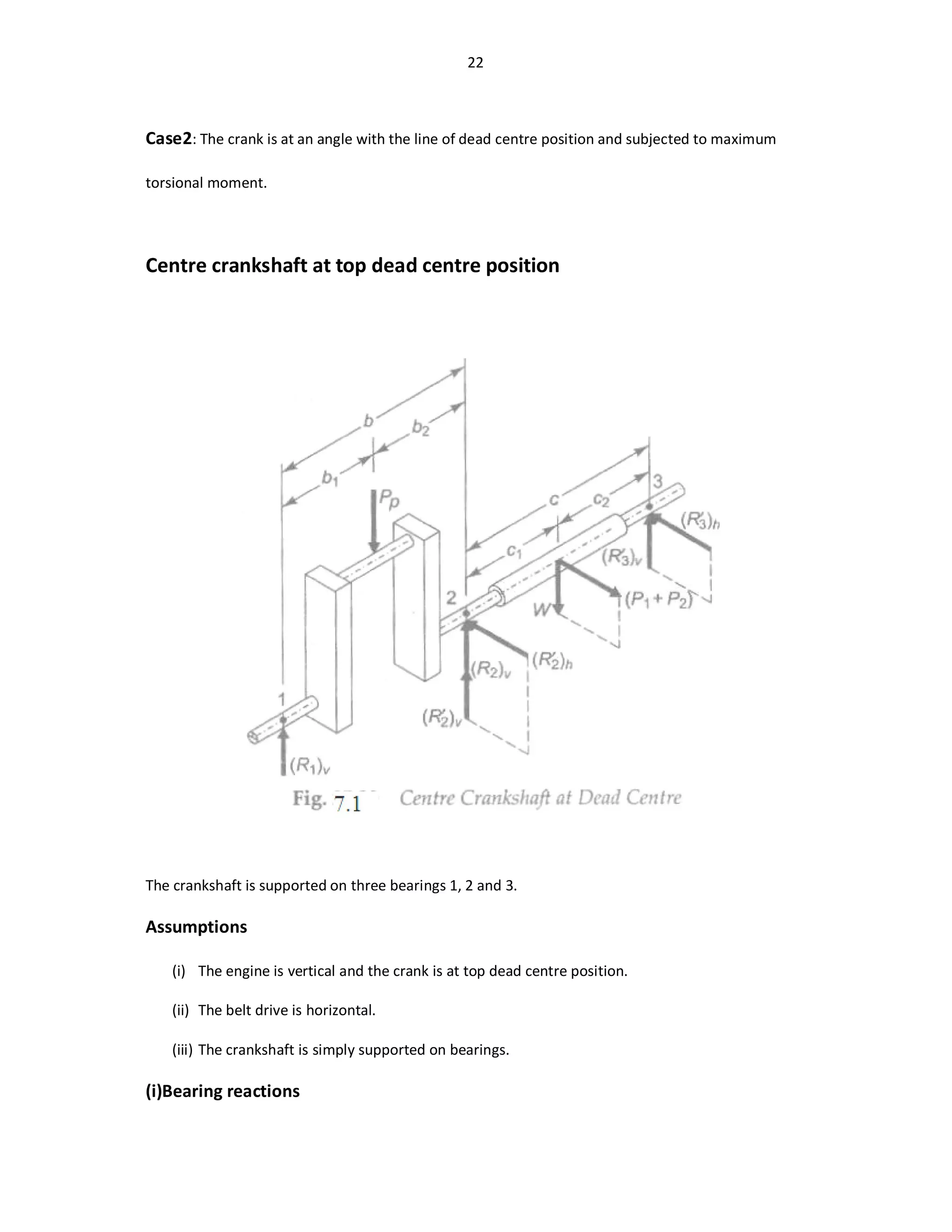
Note: When the distance b between the bearings 1 and 2 is not specified, it is assumed by the
following empirical relationship:
b=2*piston diameter or b=2*D
26. 26
(ii)Design of crank pin
The central plane of the crank pin is subjected to maximum bending moment. Suppose,
dc=diameter of crank pin(mm)
lc=length of crank pin(mm)
σb=allowable bending stress for crank pin(N/mm^2)
The bending moment at the central plane is given by,
(Mb)c=(R1)vb1
I= /64
y=dc/2
σb=(Mb)cy/I
Substituting,
(Mb)c=( /32) σb
The diameter of the crank pin can be determined using the above equations.
The length of the crank pin is determined by bearing consideration. Suppose,
pb=allowable bearing pressure at the crank pin bush(N/mm^2)
pb=Pp/dc*Ic or Ic= Pp/dc*pb
(iii)Design of left-hand crank web
Suppose,
w=width of crank web(mm)
t=thickness of crank web(mm)
Here,
t=0.7dc
w=1.14dc where dc=diameter of the crank pin(mm)
27. 27
The left-hand crank web is subjected to eccentric load(R1)v. There are two types of stresses in
the central plane of the crank web, viz., direct compressive stress and bending stress due to
eccentricity of reaction(R1)v.
The direct compressive stress is given by,
σc=(R1)v/wt
The bending moment is given by,
Mb=(R1)v*[b1-(lc/2)-(t/2)]
I=w /12
y=t/2
σb=Mb*y/I
Substituting,
σb=
=
The total compressive stress is given by,
(σc)t=σc+σb
It should be less than the total allowable bending stress.
(iv)Design of right-hand crank web
The thickness and width of the right-hand crank web are made identical to that of the left-
hand crank web(since they are identical from balancing considerations).
(v)Design of shaft under flywheel
The central plane of theshaft is subjected to maximum bending moment. Suppose,
ds=diameter of shaft under flywheel(mm)
The bending moment in the vertical plane due to resultant belt tension is given by,
28. 28
(Mb)v=(R3’)vc2
The bending moment in the horizontal plane due to resultant belt tension is given by,
(Mb)h=(R3’)hc2
The resultant bending moment is given by,
Mb=√([(Mb)v]^2 + [(Mb)h]^2)
=√([(R3’)v*c2]^2 + [(R3’)h*c2]^2)
Also, Mb= (π(ds)3
/32) σb
Therefore, the diameter of the shaft under flywheel (ds) can be calculated.
Viva Questions
1. What is crank shaft and why is it used?
2. What are the major stresses induced in the crankshaft?
3. What is difference between center crankshaft and side crankshaft?
4. What is single throw and multi throw crankshaft?
Practice problem
1. Design a plain carbon steel crank shaft for a 0.40 m by 0.60m single acting four stroke single
cylinder engine to operate at 200 rev/min. The mean effective pressure is 0.49 MPa, and the
maximum combustion pressure is 2.625 MPa. At a Maximum torsional moment when the
crank angle is 36 degree, the gas pressure is 0.975 MPa. l/r=4.8. the flywheel is used as
pulley weighing 54.50 kN and total belt pull is 6.75kN.